Jagau's successful ZPM replication

  • 3.7K Views
  • Last Post 30 June 2023
  • Topic Is Solved
Jagau posted this 09 December 2022

My replication of Figther's ZPM. As my two coils were already mounted on an AMCC320 I was able to replicate quickly.
In the first image the 2 coils mounted on the AMCC320


In the second image when the power supply is turned on at 24 volts DC he sees an input power of 4.32 watts on 24 volts and 180 ma when my TL494 oscillator is supplied to both coils through an IGBT pulsed at 38.2% on the high side. Channel1 is IGBT pulse 


Image of the oscilloscope with the current probe on the PS

You can notice that the oscilloscope show on a my TEK current probe (green) 292mv =292 ma  (rectangular form) and 38.2% DTC

Last image the 118 volt 4 Watts lamp lit with 34 ma x118.8v = therefore 4.0392 watts of power produce at the output on a large capacitor and 4 diodes in parallel in order to produce an almost pure DC which can be read by the 2 DDMs

Calculation of input power in DCM mode with reactive component.

As indicated by the power supply we have an instantaneous pulse power of 4.32 watts, this is the instantaneous power not the average power over time.

V and I is what PS provided a DM as wrong lecture for input due to high frequency so to calc PIn we take well known formula for inductor.

Irms on scope is 0.292 Amp, DC voltage is 24volts

Pin= I*V*sqrt(Duty_Cycle)/sqrt(3)


Pin= 0.292 Amp x 24 Vdc x sqrt 0.382 / sqrt 3 = 2.533 watts

So for  Pout of 4.032 watts  i need only 2.533 watts at input, Still a pretty good COP
Jagau

Order By: Standard | Newest | Votes
Jagau posted this 09 December 2022

My replication of Figther's ZPM. As my two coils were already mounted on an AMCC320 I was able to replicate quickly.
In the first image the 2 coils mounted on the AMCC320


In the second image when the power supply is turned on at 24 volts DC he sees an input power of 4.32 watts on 24 volts and 180 ma when my TL494 oscillator is supplied to both coils through an IGBT pulsed at 38.2% on the high side. Channel1 is IGBT pulse 


Image of the oscilloscope with the current probe on the PS

You can notice that the oscilloscope show on a my TEK current probe (green) 292mv =292 ma  (rectangular form) and 38.2% DTC

Last image the 118 volt 4 Watts lamp lit with 34 ma x118.8v = therefore 4.0392 watts of power produce at the output on a large capacitor and 4 diodes in parallel in order to produce an almost pure DC which can be read by the 2 DDMs

Calculation of input power in DCM mode with reactive component.

As indicated by the power supply we have an instantaneous pulse power of 4.32 watts, this is the instantaneous power not the average power over time.

V and I is what PS provided a DM as wrong lecture for input due to high frequency so to calc PIn we take well known formula for inductor.

Irms on scope is 0.292 Amp, DC voltage is 24volts

Pin= I*V*sqrt(Duty_Cycle)/sqrt(3)


Pin= 0.292 Amp x 24 Vdc x sqrt 0.382 / sqrt 3 = 2.533 watts

So for  Pout of 4.032 watts  i need only 2.533 watts at input, Still a pretty good COP
Jagau

Jagau posted this 09 December 2022

Again the only lamp lit has a DDM of 34ma and a voltage of 118 volts

to know the COP Pout / Pin
it is so complicated? no just a little understanding

For those who doubt it's your right, I don't want to convince anyone here but it's already in the past for me, these are old experiences. In order to have more precision in my data I used a dedicated current probe for oscilloscope, accurate up to 50Mhz, which is very different from the shunt resistor.

Jagau

Fighter posted this 09 December 2022

Hi Jagau,

Thank you for presenting a new successful ZPM replication and a new example of the input decreasing effect !

I hope you don't mind, I added the word "successful" to the title of your thread.

Your ZPM replication and this thread are now officially tagged with the "Beyond-Unity" tag.

Much appreciated ! ☺️

Regards,

Fighter

"If you want to find the secrets of the universe, think in terms of energy, frequency and vibration."
Nikola Tesla
Atti posted this 09 December 2022

That's what it's about. This is exactly why I need to buy a bigger Amcc. The strength of the effect is clearly visible. As others have suggested: LET'S EXPLORE THE EFFECTS. It can be seen that it will have results.

  • There must be some reason for the operation. So the reasons must be collected.
    - There must be a reason for the unsuccessful operation. This is the opposite of the previous statement.

Atti.

Itsu posted this 09 December 2022

Jagau, 

looking promising, especially when still at such low frequency (1kHz) and not at any resonance 👍

One thing intrigues me, when you say: "I used a dedicated current probe for oscilloscope, accurate up to 50Mhz, which is very different from the shunt resistor".

What do you mean by "very different"?   

It should be the same IMO, as a matter of fact, i always (when possible) use a 1 or 0.1 Ohm csr (shunt) to double check the current probes outcome and if there is a difference i would trust the csr (shunt) above the current probe.

Thanks,  Itsu

Jagau posted this 10 December 2022

Changed my P6021 to current probe AC/DC newer A6302 these are really good working tools. There are several advantages and much more accuracy to use a current probe instead of a shunt resistor.
The Tektronix site explains very well why, when you take the time to read its user manual, you discover many advantages and why they are so expensive to buy.
You have the same current probe as me so I don't understand why you ask the question, I will never believe that you haven't noticed the advantages?

Quote

i always (when possible) use a 1 or 0.1 Ohm csr (shunt) to double check the current probes outcome and if there is a difference i would trust the csr (shunt) above the current probe.


So you don't trust your scope current probe which is much more precise than a shunt resistor?
I don't understand what you want to tell me, I made a very simple demonstration with supporting evidence but even with that you refute the effect and do not want to evolve with all of us here.

You don't have to believe me as I mentioned in my last post butand you should be happy with what I've accomplished and let me be happy myself with what I achieved.

Jagau

cd_sharp posted this 10 December 2022

Hey, Jagau

Congrats, very good work! Thanks for sharing!

Stay strong!

If you know how to build such a device and you're not sharing, you're a schmuck! - Graham Gunderson

Itsu posted this 10 December 2022


Jagau,

i just asked you why you say it’s very different, a simple question IMO as normally the results should be very similar.

But i guess you mean different concerning the handling and the convenience to plug it in the circuit anywhere you like, and i agree, that’s very different compared with a CSR.

I did not refute anything, why so upset if anyone asks a simple question.

I do not trust my A6302 current probe as in the last 10 years i have used them i have my 5th one now, so they are not that reliable, you will notice that sooner or later.

You will not notice when they go defective most of the time and will give you false readings, therefor i always, when possible, do a compare with the P6021 AC only probe when appropriate or with a simple 1 Ohm 1% induction free resistor.   Check, double check.

I am happy for you and everyone who is able to present a COP > 1, but you should expect and accept that people start asking questions, perhaps to replicate your success.

Itsu

Jagau posted this 10 December 2022

An oscilloscope probe must be calibrated before being certain of its measurements,

it is common sense that speaks.

It's not a simple question that you ask, it's just to sow doubt.

Leave me alone with your questions that have nothing to do with how I got to this COP.
Jagau

Fighter posted this 10 December 2022

Quoting:Itsu

I did not refute anything, why so upset if anyone asks a simple question.

I do not trust my A6302 current probe as in the last 10 years i have used them i have my 5th one now, so they are not that reliable, you will notice that sooner or later.

You will not notice when they go defective most of the time and will give you false readings, therefor i always, when possible, do a compare with the P6021 AC only probe when appropriate or with a simple 1 Ohm 1% induction free resistor.   Check, double check.

I am happy for you and everyone who is able to present a COP > 1, but you should expect and accept that people start asking questions, perhaps to replicate your success.

Itsu

Let me guess, we have "measurement errors" here too, isn't ?..

That's not a question, that's a insinuation that Jagau's probe is defective.

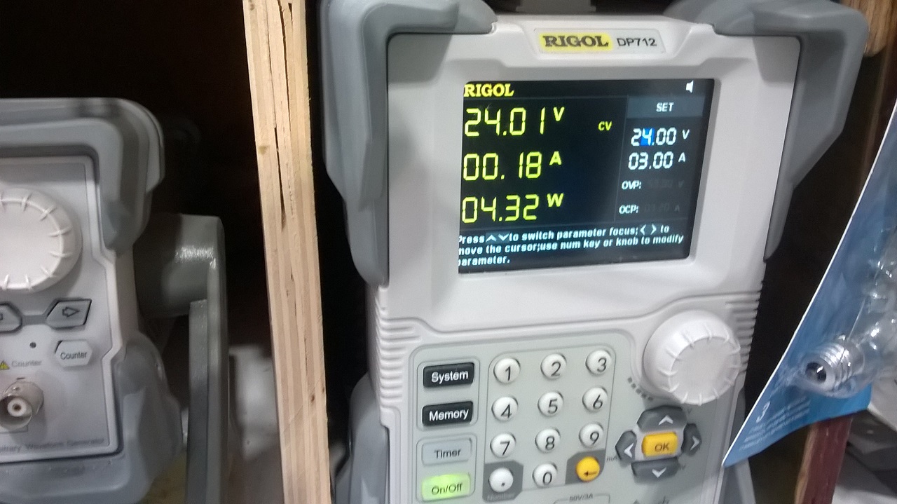
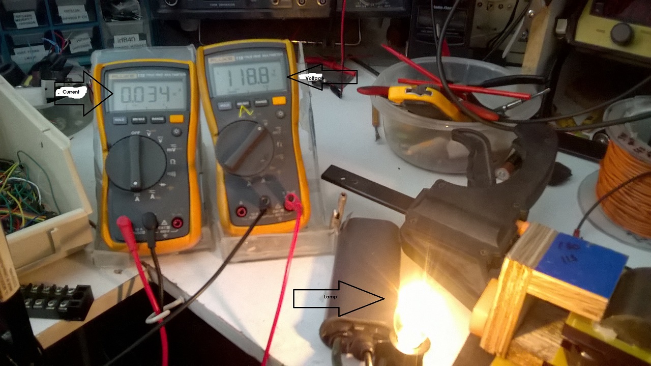
The 2.533W input with 4.032W output is 1.6 COP and it surely is a pretty good COP but...

So "1.6 COP, nah...", right ?

Let me ask you something, in 10-15 years on overunity site how many times you had a device showing at least a bit over 1 COP ? I will tell you: NEVER. And now you act like your entire life you worked only with devices having COP 10 and above ! Really ?...

You know why ? Because that's the general attitude there about everything: "nah...". And the result is that site full of "experts" never came with anything new ever in all these 15 years. Because everytime someone come there with a device to present it all the "experts" start struggling to enforce it in the "measurement error" scenario, ineventing "rules" when necessary, ignoring data when necessary, doing everything to come to the unique conclusion present on that site since its beginning: "nah...".

Jagau is presenting the correct formula to calculate the correct input for PWM input using frequency, duty-cycle, voltage and current; everything documented by multiple very valid documents and online calculators. You replied again with some kind of "nah...".

I already see a pattern here, you simply can't get rid of that attitude, isn't ?..

Let me tell you something, we'll not gonna have the b*sh*t from that site imported here, you got my word. Also harassing our members, especially the ones from our core team is a big NO, there will be a warning then the ban.

You may consider this post as that warning.

Continue with this attitude of saying "nah" to everything you see here and soon you'll return to your buddies who can't think outside of the box, can't get over their standard "measurement error" so called conclusion.

I'm sorry, I thought you came here to really try a replication but the "conclusion" you came here looking for is so obvious.

Even if you have examples of ZPM's input reduction effect, your main preocupation was not to check what's different between what I presented or Atti presented or Jagau presented, instead you jumped to make measurements on a device which is not having that effect because that's the "conclusion" you came here for: ZPM is consuming tens and tens of watts. Are you sure what you measured is a ZPM ? Because without the input reduction effect the measurements are useless but very helpful for the "conclusion" you came here for.

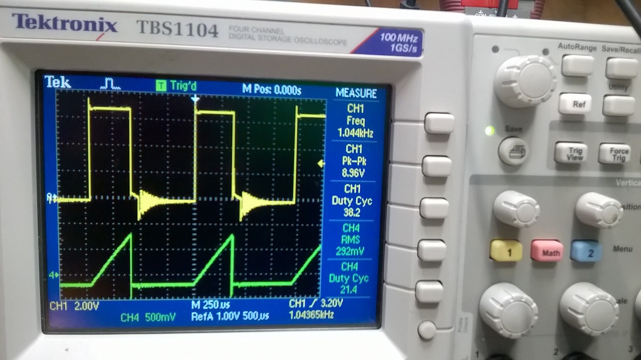
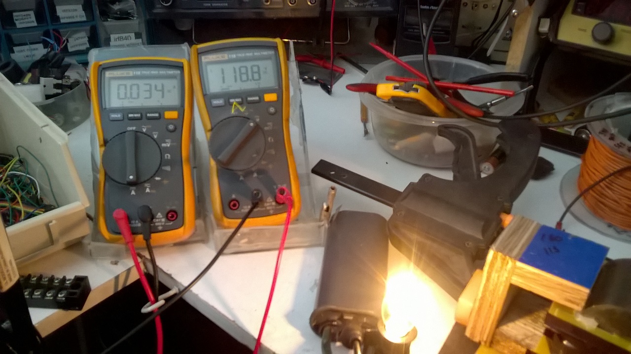
This is the voltage and current going across and through the bulbs when at 378kHz resonance as before, again with 20A of P2P current, but a mere 4.7W of power.

There is no real power there...

Ask yourself, if that's the extra-power (with MOSFET off) you see in a device without the input decreasing effect, what extra-power will be there when the effect is present ?

After all your general opinion about this kind of research can be resumed to what you said when you came here:

You keep mentioning Akula or Don Smith's devices as examples, but to my knowledge nobody was able to do a succesfull replication of either devices, so taking them as good examples looks dubious to me at the least IMHO.

So basically what Tesla, Bearden, Don Smith, Akula, Kapanadze, Gunderson etc. did explained and demonstrated are not good examples and are dubious just because we don't know anyone who replicated them, right ? Then what are you doing in this field of reasearch if you really don't believe in anything like this ?..

Anyway, remember, we will not have the useless and destructive attitude from overunity site imported here. I promise that and I'll make sure of that.

Regards,

Fighter

"If you want to find the secrets of the universe, think in terms of energy, frequency and vibration."
Nikola Tesla
bigmotherwhale posted this 11 December 2022

Congratulations Jagau, nice work

There is another option for measuring power and thats on the input side of the PSU, especially at higher power levels as no one can really argue with that imo, also you could try a large capacitor, I did some experiments where i could see how long it took for the cap to empty, my best results ie lowest power in took longer to drop in voltage, not that im debating your results of course... 

Can you measure the freqency of the ringdown on the primary after the input pulse please? 

Thanks 


Close