
I transferred my thread on Non Linear Resonance here to BeyondUnity.org
What we consider to be empty space is merely a manifestation of unawakened matter. N.T.
I transferred my thread on Non Linear Resonance here to BeyondUnity.org
What we consider to be empty space is merely a manifestation of unawakened matter. N.T.
yes indeed there has been a positive development
in the sense that the subject of nonlinear resonance is always active
but I have no objection to bring this to the community,
I asked myself the same question,
to move it in part if it can benefit a larger number no problem, I just didn't want to distract the other threads ?
Jagau
What we consider to be empty space is merely a manifestation of unawakened matter. N.T.
hi vidura
Can you ask to Yo,you know it better than me, if it does not bother to transfer the thread to the community, tell him that they feel very free with his desire, and on your side is it ok for you?
We would call the new non-linear resonance for all thread
Jagau
What we consider to be empty space is merely a manifestation of unawakened matter. N.T.
About the leds project.
After almost 2 weeks, the batteries in series have started to drop slowly except that in reverse which is still held at 1.4 v
I learned a lot with this very simple little circuit and I plan to develop one with more power.
Jagau
What we consider to be empty space is merely a manifestation of unawakened matter. N.T.
Small update
On the circuit that I sent you,
the more I increase the load at the output by increasing as an example the capacity of capacitor
the more consumption at the input decreases and the output voltage increases with no change in frequency,
very interesting observation, under study
Jagau
What we consider to be empty space is merely a manifestation of unawakened matter. N.T.
Hi all
As you can imagine, it is not only us who seek to understand the mystery of the small lamp of Akula.
I recently found a very interesting article from an Indian engineering college which offers a topoly buck boost converter as Yo's proposal. They title their articles:
Self Powered Buck-Boost Converter for Low-Voltage Energy Applications.
I put it in paste.
Jagau
What we consider to be empty space is merely a manifestation of unawakened matter. N.T.
Hi my friends
I am preparing an update for my thread
I haven't forgotten you, see you soon
Jagau
What we consider to be empty space is merely a manifestation of unawakened matter. N.T.
update
Hy my friends
By carefully studying the very well-known schematic of A. Melnichenko;
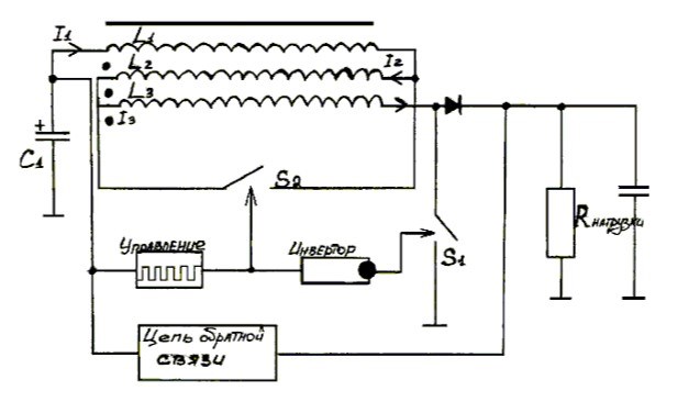
In a complete cycle we can divide it into 4 equal parts of 90 degrees.
I redid this schematic so that it works in the project of the small led lamp, because this small lamp uses the basic principle of the operation of this schematic.
We must have 3 coils, a diode and a capacitor, I will show you in a short video all the power to develop by this arrangement of 3 coils of which 2 transmit the starting impulse and I cancel the one of the middle by disconnecting it in a natural way and by reconnecting it in series and only by capturing the way in which the coils interact with each other, as Akula said, you must capture the functioning of your coils first.
No need for a complicated switch, just think about it. When I transmit the pulse (phase 1 and 3) I am in very low inductance about 45 microhenries, therefore in energy saving, when I receive at the output the inductance goes from 45 microhenries to 350 millihenries, which gives me a great increase in power.
The schematic is the basic idea of the operating principle but if you plug it in as it is present, it does not work as I had already demonstrated in another post by shorting a single inductance we can not have an inductance increase in that this during the relaxation (disconnection) of the circuit in phase 2 and phase 4 of a cycle as demonstrated by CD in another post.
I am preparing this short video to show you my latest advancements in this project.
Jagau
What we consider to be empty space is merely a manifestation of unawakened matter. N.T.
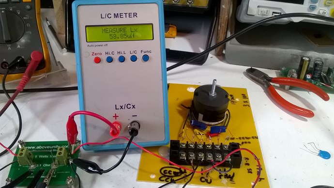
So this simple confuguration gives me at the input inductance is 58.85 uh
and at the output inductance is 348.4mh
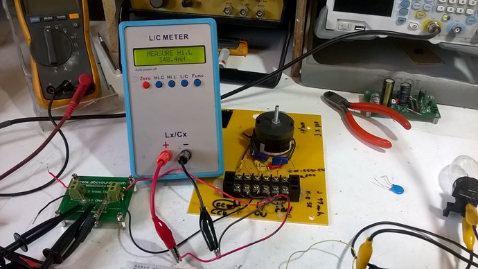
The setup
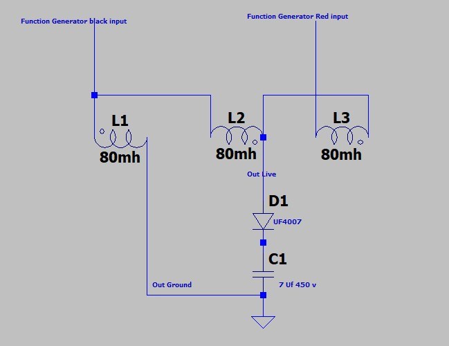
It is the way in which I connect the 3 coils which give me this advantage. As the inductance increases considerably you can see in the video the effect produced.
As you will notice in the setup, it is imperative to have a square wave AC, ie it goes through zero and increases in negative with the same amplitude as in positive.
Function generator who act like S1 in melnichenko schematic and no need of S2 switch,
And more at 21 Khz a functiongenerator have an outputt power contrill by the amplitude of about 45 milli watt and it is normal. I apply this 45 mw to this set up
Here the difference between a square wave AC and DC.
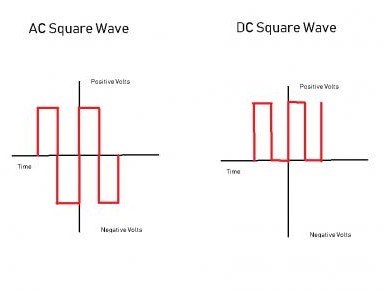
The effect is completely different when I use AC,
so AC square wave is better.
The video is almost finished, I'll get back to you with that
jagau
What we consider to be empty space is merely a manifestation of unawakened matter. N.T.
Hi my friends
Here is the video:
Scope show across 0.1 ohm board current of 19 ma and voltage 5 volts, 95 mill watts or 0.095 watt at 19 khz AC square wave at resonant frequency and we get 550 volts RMS in 2-3 sec.
At output i discharge an incandescent lamp of 10 watts 120 volts in, note the very fast increase in voltage with so low input power. I will surely lit some leds in my project of lamp with this coils configuration.
I would never have thought of one day lighting an incandescent lamp with the very low power of a function generator.
Asymetric transformer plus resonance is the perfect combination to get beyound unity.
Next goal, would like this leds lamp a project succeeds.
What we consider to be empty space is merely a manifestation of unawakened matter. N.T.
The system has a recharge time of 2 to 3 to make an average with 2.5 we have e = (cv square / 2) = 1.059 watt /2.5 second= 0.4235 watt second and and with the amplitude of the F.G. completely closed, I still have 47 volts RMS,
The 10 watt 120 volt lamp is only to demonstrate the rapid increase in charge mode.
The LEDs take almost nothing. I will demonstrate later.
Jagau
What we consider to be empty space is merely a manifestation of unawakened matter. N.T.

No one online at the moment
