
I transferred my thread on Non Linear Resonance here to BeyondUnity.org
What we consider to be empty space is merely a manifestation of unawakened matter. N.T.
I transferred my thread on Non Linear Resonance here to BeyondUnity.org
What we consider to be empty space is merely a manifestation of unawakened matter. N.T.
Hello
After having made different test on different type of capacitor
the oil capacitors are very efficient and the chemical capacitors with a low ESR are also very good.
I redid my coils with a higher inductance and I now reach 642 volts DC on output capacitor 7 uf 660vac
Jagau
What we consider to be empty space is merely a manifestation of unawakened matter. N.T.
Hi all
Another important detail about building
The Rx coil, the one that receives the energy,it is the first to be rolled up,
it must be followed first by the 2 bifiliary windings,
If you do it backwards it will only work at half the power. I will explain in another post why this happens.
Another thing, the gap must be between the coils and not between the ferromagnetic material as some have interpreted, very important. For those who have already experienced this phenomenon 2 coils effect it's like two plates of a capacitor, I think Akula had guessed it, think about it when you build the gap.
Jagau
What we consider to be empty space is merely a manifestation of unawakened matter. N.T.
Hi all
Even if I am not often present in the forum these times do not worry, I experiment a lot with all kinds of different parameters, will come back with other very encouraging results
Jagau
What we consider to be empty space is merely a manifestation of unawakened matter. N.T.
Hi all
As Ruslan says in his video, an important point is when you meet this figure.
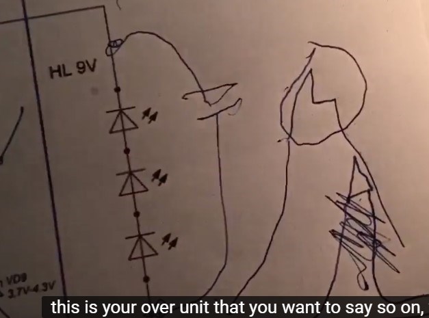
I did it with the beat of 2 frequencies
photo to come, And explain it to you in detail
jagau
What we consider to be empty space is merely a manifestation of unawakened matter. N.T.
My friends
The last few days I've been working on this thread's project a lot. I have tried several ways to virify the last results and I always arrive between 2.9 and 3.2 of A.U.No matter how I go about it, I always get more or less the same results.
So when I will have succeeded in controlling the input impedances (Z) in relation to the circuits involved, I calculate a result much greater than that achieved. It may be a dream but a goal to achieve.
Firstly, as Don Smith said:
The people who have successfully duplicated my experiments are those who have successfully matched the various impedance of the circuits involved.
I'm working on it now and it's a noble goal. This project is in serious development.
Jagau
What we consider to be empty space is merely a manifestation of unawakened matter. N.T.
HI
It's a very good idea and I will put the circuit in place with an
Up to date,
Regarding impedance adaptation, you will find the context in this article of what DonSmith is talking.
https://en.wikipedia.org/wiki/Impedance_matching
I mean adapting one circuit to another for maximum energy transfer and without distortion of the source circuit.
In my circuit it makes all the difference, will show result later.
Jagau
What we consider to be empty space is merely a manifestation of unawakened matter. N.T.
I think having a new thread on the subject will be really an important point for our research that all of us do.
The game of impedances is very important not only in the antennas but also between the different circuits that we use.
As an example a microphone, a guitar or an op amp between two circuits, connected in buffer mode which has a very high input impedance compared to the output having a very low Z, to name only those.
The energy transfer is better when the impedances are adapted and this does not distort the source.
Jagau
What we consider to be empty space is merely a manifestation of unawakened matter. N.T.
Hi all.
@Jagau.
Yes, your circuit is 80% dependent on impedance maching
between both Generator / Load and 20% ferro-resonance.
I tell you that I managed to replicate it 100%, but only after
to properly couple the two.
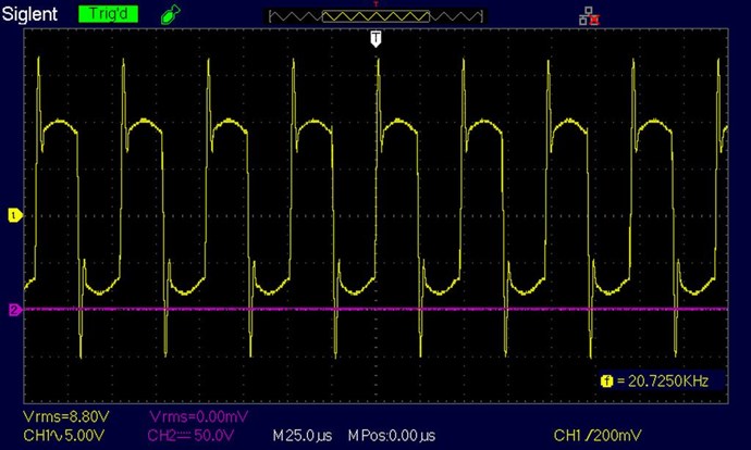
Here is an image of the oscilloscope.
As I commented earlier, the leakage inductance is the
causing to open that window to the sea of energy and the capacitor
to store it for later use.
Your two inductors coupled in non-inductive mode to be
biased cause leakage inductance to grow and polarize
the external environment to them, is that gap between them of which you speak.
If the current flowing through both is such that Ur is maximum
then the collector coil is capable of capturing said energy.
Thank you all in advance.
YoElMiCrO.
Hello yo
I see that we are on the same way of thinking,
as much in the impedance adaptation as with the gap which is very subtle but very important.
The source deformation is minimal and in addition a surprise addition in the peaks voltage.
Well done we are all on the right track and it will be very beneficial for everyone in this forum.
thank you for sharing my friend
jagau
What we consider to be empty space is merely a manifestation of unawakened matter. N.T.
Hi all
A circuit update more easy to read, 100 turns each and follow the dot.
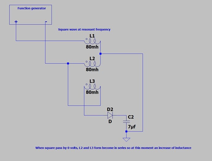
The one i am working now. Do not forget the gap between the coils, this circuit is very simple but requires attention to the assembly and like the CD said,
it is necessary to understand the scene that the coils and how they work between them in order to connect them well,
Another update will follow with an emitter follower and an ideal op amp (TL084) in order to adapt the impedances well.
Jagau
What we consider to be empty space is merely a manifestation of unawakened matter. N.T.

No one online at the moment

