
I transferred my thread on Non Linear Resonance here to BeyondUnity.org
What we consider to be empty space is merely a manifestation of unawakened matter. N.T.
I transferred my thread on Non Linear Resonance here to BeyondUnity.org
What we consider to be empty space is merely a manifestation of unawakened matter. N.T.
Hey, Jagau
From what I remember, it's about making current flow from a greater voltage "+" to a lower voltage "+". Can you please post a schematic of the circuit you are describing, here or in another thread? I'd "visit" again someday the Akula lantern with lots of joy.
Thank you
If you know how to build such a device and you're not sharing, you're a schmuck! - Graham Gunderson
Good morning all
After 3 days, without interruption the small circuit does not want to fall.
I added 3 other LEDs for a total of 9 LEDs.
The 3 small AAA rechargeable batteries did not decrease by 1 millivolt in 3 days, on the contrary, they remained stable.
A first observation; taken with the oscilloscope shows that the recharging of the setup is exactly 1/4 of the resonance frequency of the main coil which is at 28khz.
Here is scope shot:
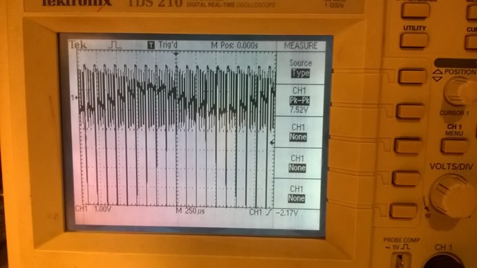
You can notice the sinus shape in the center.
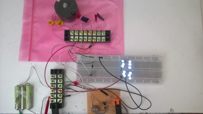
A view of complete set up, circuit, potcore, led and batteries:
Did anyone try my first circuit at the start of the thread?
Other observations, photos and a circuit will follow.
P.S. John Bedini wrote on his web page: ''This has been on my pages forever, but nobody understood it.''
I wonder what he meant by that
Jagau
What we consider to be empty space is merely a manifestation of unawakened matter. N.T.
Hi all
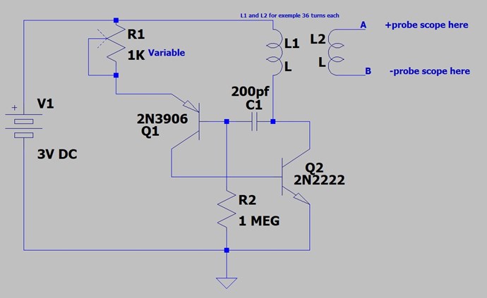
I would like to present you a very simple circuit to make but how useful.
It's the same one I use for what's going on in the project above.
You can use the 2 inductors of your choice as long as they are on the same core, for mine I use a potcore.
As soon as they are connected by 3vdc it starts to oscillate on its own and in addition if you look on your oscilloscope at point A and B it adjusts by itself to the resonance frequency. Very nice little circuit simple and easy to do.
Thereafter I will be able to explain to you how I achieve what I did.
I think it was one of Akula's favorite circuits but modify by me as you can see at the beginning of this thread.
P, S, The variable resistor 1K does not change the frequency, it is there to adjust the gain of the circuit only.
Jagau
What we consider to be empty space is merely a manifestation of unawakened matter. N.T.
Hi Jagau. Does one of your l2 leg are not connected to anything like in your schematics on the top of this tread?
It will be nice to know a bit more on your experiment.
Thank you!
Hey, Jagau
I'm experimenting in the non-inductive circuit, but I'll read your explanations with great commitment. Thanks!
If you know how to build such a device and you're not sharing, you're a schmuck! - Graham Gunderson
Hi wistiti
Yes these are the first modifications at the beginning which had been made in the system has had an evolution. It is for this reason that I redid the basic circuit as simple as possible above, it is the same as on the little brown board on the photo above. The goal is to progress slowly but surely in the explanation of the circuit if you build the last little circuit very simple above, I could guide by the following it will be less complicated like that, I think.
@ CD
I understand you very well CD, there are so many interesting things to do in this forum that we do not want to disturb others in our own experience, but it is part of the game. Don't worry CD, I'm also following your experiences with a lot of interest.
Other questions?
Some news:
At the fourth day the system still works as well the voltages of the 3 batteries are always higher than the nominal voltage of each which is 1.25 volts, they stand between 1.3 and 1.4 is great.
Another observation, the mornings of strong sun the ions increases a little and the evening decreases a little but never below 1.3 each.
Jagau
What we consider to be empty space is merely a manifestation of unawakened matter. N.T.
Hi all
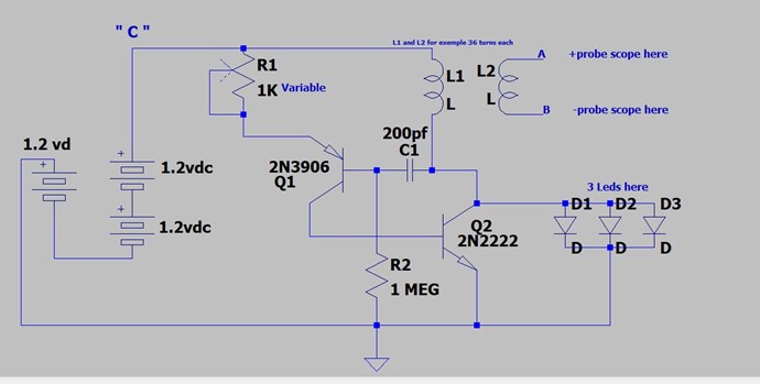
Now we will add 3 LEDs in parallel and 2 others battery in the circuit.
Place an ammeter at point C and adjust the 1K pot to get 3 milliamps.
I hope you have successfully completed this part because the next one is the most important.
News
Since last saturday, February 15, the system is still working well. The LEDs are on and the voltage barely fluctuates.
Jagau
What we consider to be empty space is merely a manifestation of unawakened matter. N.T.
Thanks Jagau for sharing! I will try to replicate when the time permits. Maybe the next weekend.
Hi Wistiti, You are welcome with any questions.
Okay
I know that rechargeable nick-cad batteries have a capacity each and a nominal voltage. So it is easy to calculate the time the circuit would operate under a certain load and the voltage would drop linearly every 24 hours.
This is not what happens, the voltage varies in + or - no more than 0.001 volts and it remains stable at above the normal nominal voltage for this type of battery which is 1.2 volts, they are all the 3 at the over of this nominal voltage and sometimes reach 1.4 depending on the hours of the day.
Another beautiful puzzle to elucidate?
Jagau
What we consider to be empty space is merely a manifestation of unawakened matter. N.T.
And now the first version of the complete circuit.
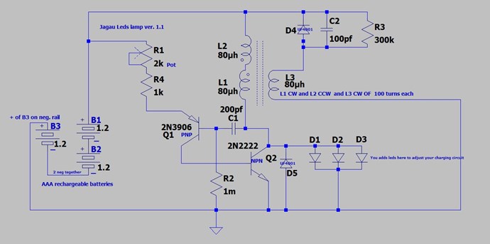
I am going there gradually so that you can understand how it works
Jagau
What we consider to be empty space is merely a manifestation of unawakened matter. N.T.

No one online at the moment


