
I transferred my thread on Non Linear Resonance here to BeyondUnity.org
What we consider to be empty space is merely a manifestation of unawakened matter. N.T.
I transferred my thread on Non Linear Resonance here to BeyondUnity.org
What we consider to be empty space is merely a manifestation of unawakened matter. N.T.
Hi Jagau,
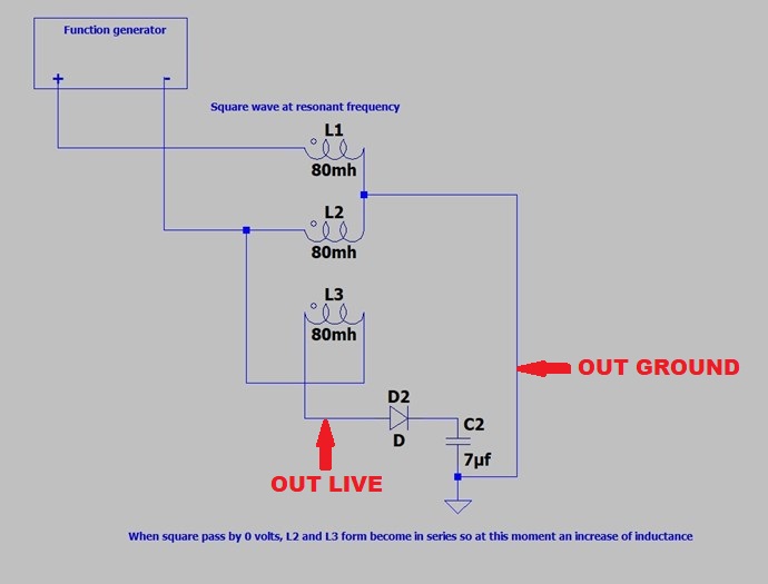
About your latest diagram (the one I used for building the device) I just want to make sure the points where I'm putting the output connector is correct. Can you confirm the output live and ground points are correct ?
This is how the device is looking like right now:
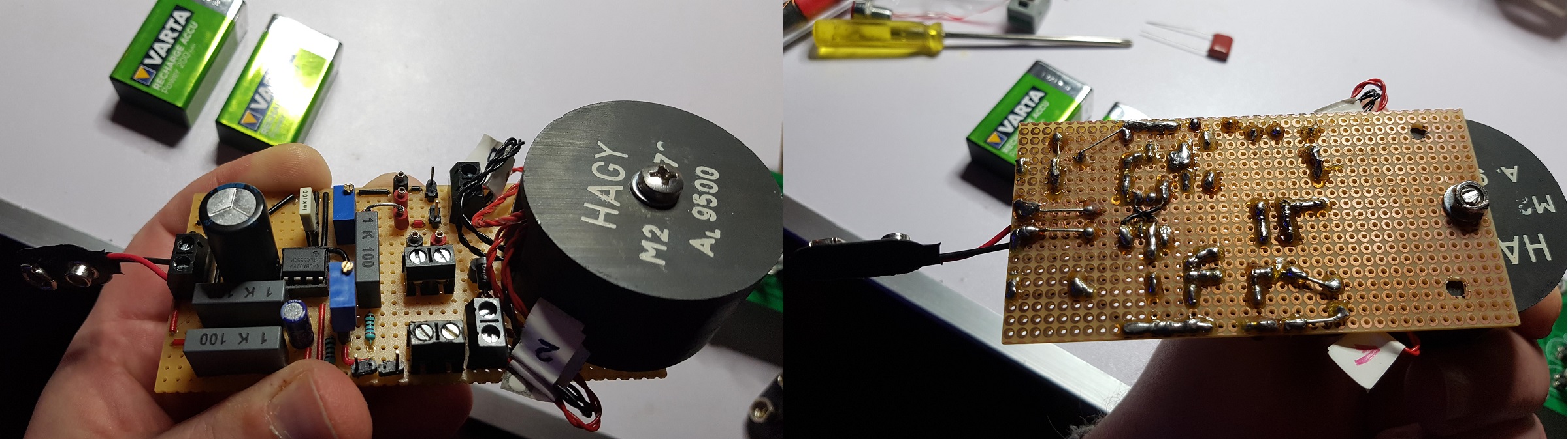
It contains your AC oscillator and your way of building the coils in a pot-core on the same PCB, the only addition is the 2200uF/25V electrolytic capacitor on input.
There are multiple measurement pins and also sockets for easily switching the essential components: oscillator's capacitor and variable resistor, the capacitor and the fast diode connected to the coils.
The output socket is not connected yet to the circuit, just wanting your confirmation before building the connections.
Thanks for your help !
P.S.: Also, the ground connector below the 7uF capacitor, is that a physical connection ? Should I connect it on the negative output of the signal generator ?
| "If you want to find the secrets of the universe, think in terms of energy, frequency and vibration." | ||
| Nikola Tesla | ||
hello fighter
I could not answer your questions, I was not at home and on vacation I do not use the internet, it's an isolated place in the forest far from everything, it makes me good for my body and my mind.
I have just arrived and I will take the time to analyze your request, but at first glance you are correct in your connections, except the mass not put to the same as the function generator.
A lot of interesting message to read on the forum, I will come back to you with more precision and by the way I wish you a very happy new year 2021
Jagau
What we consider to be empty space is merely a manifestation of unawakened matter. N.T.
Hello fighter
Your circuit board is very well done, I see that you are an experimenter in all details, thank you for showing it.
After analysis as I told you your connections are correct and for the ground it must be separated from the F.G.
With coils of 100 turns the frequency with dot on schematic you will obtained will be between 26 to 29 Khz and your voltage approximately 50 times that of the input, depending on the parameters of your potcore with 23 awg
I can't wait to hear your results
Jagau
What we consider to be empty space is merely a manifestation of unawakened matter. N.T.
The construction of a zero crossing detection circuit goes well with the way switches (mosfet) are to be positioned in order to precisely control the 4 phases of a sine wave.
I wanted to make it a separate thread but I think it fits well here in the phase control of an asymmetric transformer.
The 4 phases of a single sine wave.
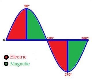
As you will notice I have built a circuit which controls these 4 states. Circuit will follow at end.
I took a small transformer to demonstrate 115 volts AC 60 cycle-
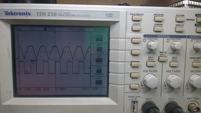
First the detection of the zero crossing
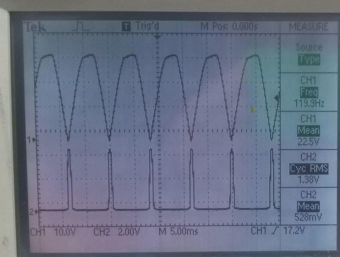
The oscilloscope allows us to see where the zero crossing occurs, and with negative cycle pass in bridge you will notice an increase to 120 hertz.
On the top waveform, see A point on schematic, that's what it looks like after passing a full diode bridge.
On the bottom form, zero crossing detection, see point C on schematic, with the 555 on shot with adjustable DTC conduction time.
From there, the conduction time of each of these phases could be adjusted with this circuit
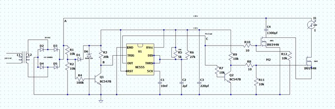
With a tlc555 configured in single-shot astable mode, at zero crossing the conduction time can be increased at will (duty cycle). A working cicuit with 4 cycles conduction adj.
With the 5K pot we can adjust S2 so that it opens and closes at the right time.
I think that a video is necessary in order to demonstrate the control of the different phases 1 and 3 (S1) and 2 and 4 (S2)
More info to come
Jagau
What we consider to be empty space is merely a manifestation of unawakened matter. N.T.
My friends
new developments this are produced in order to improve aboveunity yield of this thread.
I am preparing a somewhat complicated post it may take a little time but it is coming
Jagau
What we consider to be empty space is merely a manifestation of unawakened matter. N.T.
Hi friends
In order to end the year on the right foot I would like to show you the again experience again a more precise way, which allowed me to go beyond unity, as a first step.
In the second I will demonstrate how to make the coils with lots of details and photos so that anyone who wants to replicate it can do it.
In the third step what I recently discovered as an improvement. It’s a lot of work to show those experiment on the web!
First stage; here a photo of the last montage with photo of the set up what the oscilloscope sees.
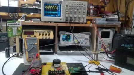
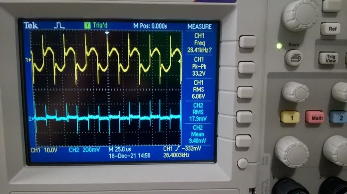
The calculation of the input power E in volts X I in amps. X t sec. (E x I xT)
Which gives 6.06 volts X 0.0179 amps. X 3 sec. = input power of 0.108474 watt or 108.474 milliwatts.
17.9 ma are took on 0.1 ohm precision resistor as we can see value on oscilloscope.
As for the output power stored in the 8uf / 660v capacitor a voltage of 335volts in 3 seconds. I have done it more than 3 times with always the same results. This gives us a stored power of CV squared / 2 = 8uf X 335 squared / 2 = 0.4489 watt or 448.9 milliwatts.
Calculation of the performance factor of n = Pout / Pin = 448.9mw / 108.474 mw = 4.1383
next will be how to make the coils.
Jagau
What we consider to be empty space is merely a manifestation of unawakened matter. N.T.
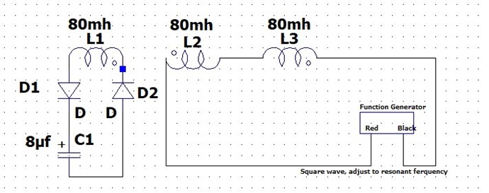
For the 3 coils of this project.
I have used on a 6800 inductance factor potcore and wound 100 turns for each of the 3 coils and it gives me 80mh for each of the 3 coils. Having tried different types of cores I have found that the results are pretty much all the same so other cores do, but keeping the same electronic diagram and the way of winding the coils.
The first coil L1 is clockwise 100 turns,
The second L2 coil is counterclockwise 100 turns,
The third L3 coil is clockwise 100 turns too.
It is important to isolate between L1-L2 and L2-L3 with electric tape the capacitive effect that this gives to the coils is important and by checking it with your LCR meter you will notice the minimal inductance with L2-L3 in series, it should be way below 100 uh if you got the job done well.
L2 and L3 are in opposite series (buck mode) and the third L1 is the output, it is very important to note that we are pulsing the coils L2 and L3 in order to have an output on L1 which is the first coil wound and which is closest to the center of the potcore given that this is the first coil that I wound.
I explained this before I think I was misunderstood, we are pulsing L2 CW and L3 CCW which are connected in series (buck) and the output is on L1.
Any questions?
Jagau
What we consider to be empty space is merely a manifestation of unawakened matter. N.T.
Hi Jagau,
Thanks for the details, so COP is greater than 4 !
Did you tried to place a load in parallel to the capacitor to consume the 448.9 mW ?
I'm just wondering if the 448.9 mW can be sustained in time.
I don't know what kind of load it should be, the voltage is too high for a 500 mW LED like this, maybe there should be a voltage conversion module on the output ?
Regards,
Fighter
| "If you want to find the secrets of the universe, think in terms of energy, frequency and vibration." | ||
| Nikola Tesla | ||
Hi Fighter
The holidays are fast approaching and time is running out, for your question yes I already demonstrated this in a video some time ago:
Think about it, can we light an 8W / 120v incandescent lamp with only the power generated by a function generator?
An 8 watt / 120 volts lamp that turns on every 3 seconds, due to a spark gap that switched from 335 volts, and is already beyondunity even after 1 second.
The purpose of this experiment is to demonstrate that there is beyoundunity, which I believe is encouraging I believe.
With the help of the members this experience could go further I think.
Example: I also tried a third coil on your ZPM and it also worked well with a little less voltage than because a higher inductance when calculating the coils in buck mode. With a potcore like you have it also works even better. The inductance calculated in buck is much lower even though the coils are 80 mh each.
I will continue to demonstrate after the holidays what other effect I have found out if there is interest in the forum.
To sum it all up: for the moment with that circuit,
i extract energy ( potentiel), but no power (wish is voltage x amperage).
Jagau
What we consider to be empty space is merely a manifestation of unawakened matter. N.T.
Hi Jagau,
I understand, I'm not questioning the above-unity, the questions I asked were because I was thinking about a possible loop to the input to make it self-running. With COP 4 I think it is possible even with some loses appearing during the voltage conversion from the output.
I mean a part of the high voltage can be converted to amperage so we can have both voltage and some amperage available after conversion of the output.
Sorry, I know I promised to join and replicate your circuit from here, I received the components a few weeks ago but unfortunately the job didn't allowed me to work on it. It was not as I planned. It's not about the lack of interest, it's about lack of time.
I'll try to recover the gap, if not in these few days remaining until the holidays then when I return from home at the beginning of January.
Thanks,
Fighter
| "If you want to find the secrets of the universe, think in terms of energy, frequency and vibration." | ||
| Nikola Tesla | ||


