
I transferred my thread on Non Linear Resonance here to BeyondUnity.org
What we consider to be empty space is merely a manifestation of unawakened matter. N.T.
I transferred my thread on Non Linear Resonance here to BeyondUnity.org
What we consider to be empty space is merely a manifestation of unawakened matter. N.T.
Hi.
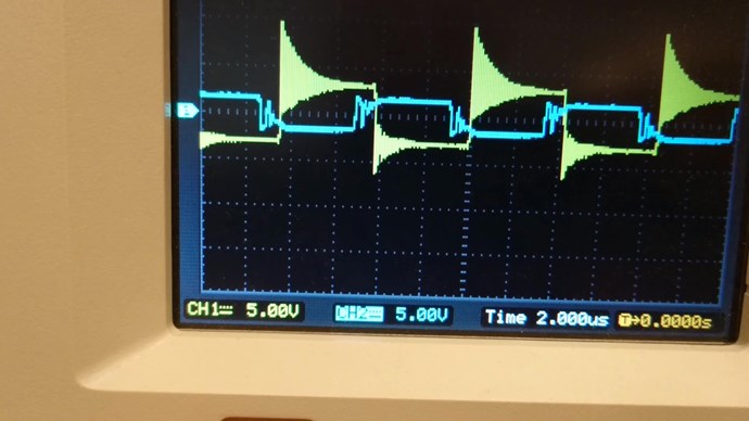
I have one of the resonance points. The yellow trail is the H bridge control sign. When this resonance point is there there is some recharging to the power supply.
Atti.
Hi Atti
there is some recharging to the power supply.
You mean that compared to the number of amps at the input you have the same result but the current drops at the input??
Jagau
What we consider to be empty space is merely a manifestation of unawakened matter. N.T.
Yes. See the video uploaded to the Vidura thread. History as well.
Hi all
A video from Don Smith who declares that several components in his system do not need to be there.
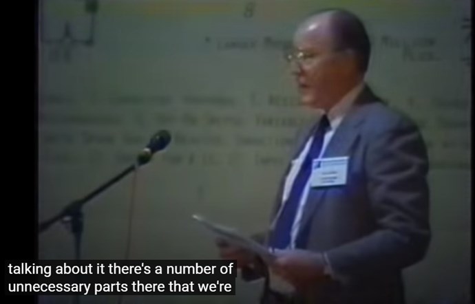
Don video; Okay you want to look at it for a couple of minutes here and then we'll start talking about, it there's a number of unnecessary parts there that we're
actually put in there because people expect to see them actually on this you
can take everything back this way and take it off of there and it will work
just fine you can also take the spark gap off of it and it will still work
just fine and the reason for that is that in the coils they have their own
specific resonance due to the fact that they have both capacitance and
inductance and when you cross that on a chart you find that that particular
length of wire will have a specific frequency and it will load and unload by
itself and you don't need spark gaps or you don't need anything else your Tesla
coils.
This is what allowed me to duplicate the voltage at will without affecting the input, as Mr Smith says and it work.
He call this D.S.E. (don smith effect)
Jagau
What we consider to be empty space is merely a manifestation of unawakened matter. N.T.
An Answer to America's Energy Deficit - 5th Edition - January 1997.pdf
An old document from Don Smith specifying that:
The electrical circuit equivalent o a bloch wall is a diode.
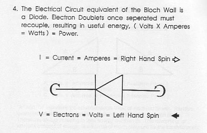
Very interesting information and many others which do not appear in more recent books
What we consider to be empty space is merely a manifestation of unawakened matter. N.T.
Hi Jagau,
I have 4 questions about your device:
I intend to experiment this with your AC oscillator, to replace the signal generator in the diagram.
Thanks for your advice !
| "If you want to find the secrets of the universe, think in terms of energy, frequency and vibration." | ||
| Nikola Tesla | ||
Hi Fighter
You will have approximately 40 to 60 times the output voltage of what you place at the input
Wound first 2 coils CW-CCW and last one CW
What people don't realize is that 2 coils on top of each other is like a capacitor, you see the effect depending on the capacity of your set up, I think you must have observed this effect with your Romanian ZPM
hope this help
Jagau
What we consider to be empty space is merely a manifestation of unawakened matter. N.T.
Hi all
Just a link test
You will be able to appreciate this document with many very interesting links
Jagau
What we consider to be empty space is merely a manifestation of unawakened matter. N.T.
Hello everyone.
@Jagau.
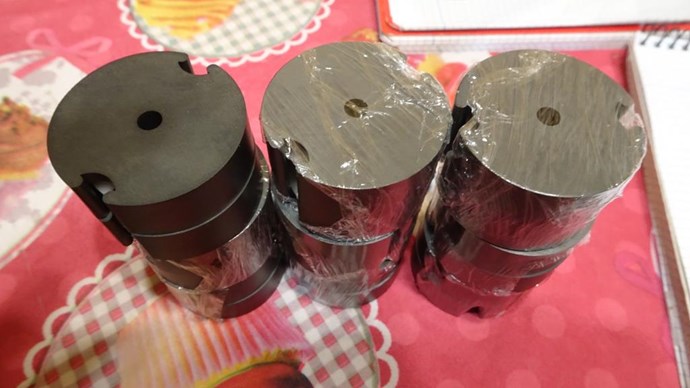
I already have the POT-Cores in hand.
I'm starting the experiments.
Buy 10, they've got 9 whole, all right.
Here's an image.
Thanks you.
YoElMiCrO.
Its's look very good Yo
Good experiment and have pleasure with this.
I am experimenting at the moment about two switching mode in different time and phase angle for coils at Zero crossing Switching (ZCD). Commonly called Synchronous switching.
Almost everyone here will be able to take advantage of this as it applies to most of our switching circuits.
I will talk about all this again when my switching circuit is ready and it will not be long. I already have good results.
have a nice day
Jagau
What we consider to be empty space is merely a manifestation of unawakened matter. N.T.

No one online at the moment


