In order to not interfere with Jagau's experiments with Dr. Stiffler's SEC technology which have many things in common with what Don Smith named "The Don Smith Effect" I'm starting in parallel with Jagau my own experiments with Don Smith's tech.
If this experiment is successful maybe we can unify the technologies these two great teachers demonstrated to us.
So below is my first post in this related thread here.
Fighter
"If you want to find the secrets of the universe, think in terms of
energy, frequency and
vibration."
Maximum Repetitive Peak Reverse Voltage (VRRM) is the maximum voltage a rectifier diode can withstand in the reverse direction without breaking down or avalanching, and rectifier diodes must have a peak inverse voltage rating higher than the maximum voltage being applied to them in the application.
In AC Peak voltage, peak to peak and RMS are 3 different measurements there is also the power of the diode which must be taken into account. You will find your answers in this link.
This ultrafast reverse recovery time diode can hold up to 1Kv p/p which means 500 V peak. Can hold 700V in DC and a maximum average forward rectified current of 1 ampere with 2.08 watts of max power taking into account the junction and ambient temperature.
Jagau
What we consider to be empty space is merely a manifestation of unawakened matter. N.T.
It arrived much earlier, their estimation for arrival was 29 March.
Its dimensions are a bit smaller than the current one, I'll need a bit of adjustments (basically to drill new holes in the plastic) to be able to fix it with plastic screws on the device's body. I'll work on replacement in the weekend.
Because it's very cheap I bought 3 units, to have reserves so I don't need another month for shipping just in case one is damaged during the experiments.
I'll come with updates.
Regards,
Fighter
"If you want to find the secrets of the universe, think in terms of
energy, frequency and
vibration."
Sorry I didn't had time to prepare this post until now but I have some updates.
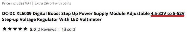
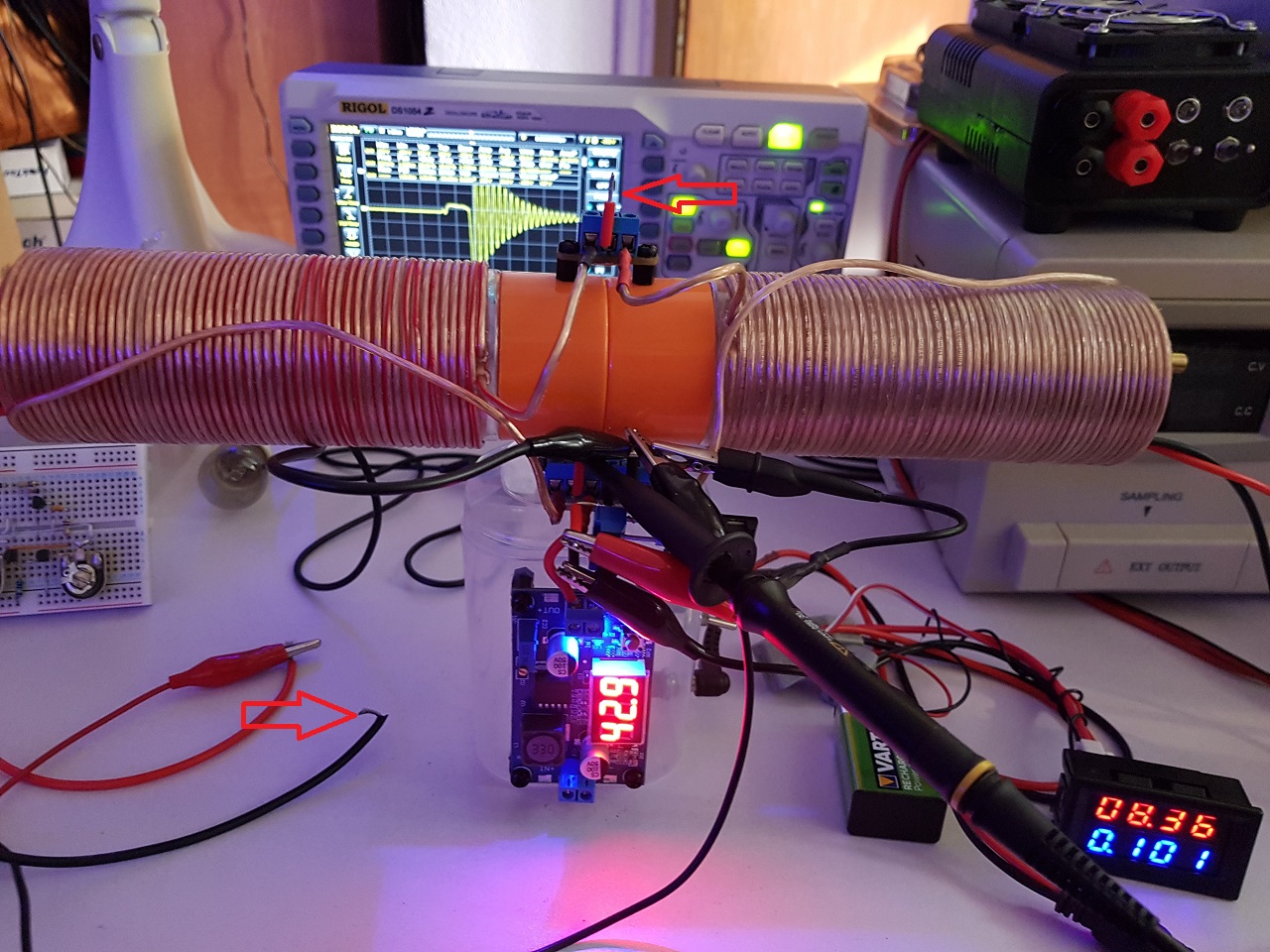
First, the new voltage booster can't reach 50V as it was advertised, it can provide maximum 42.9 V.
I'll check the other two I bought to see if this one is defective or the specifications of the vendor were wrong.
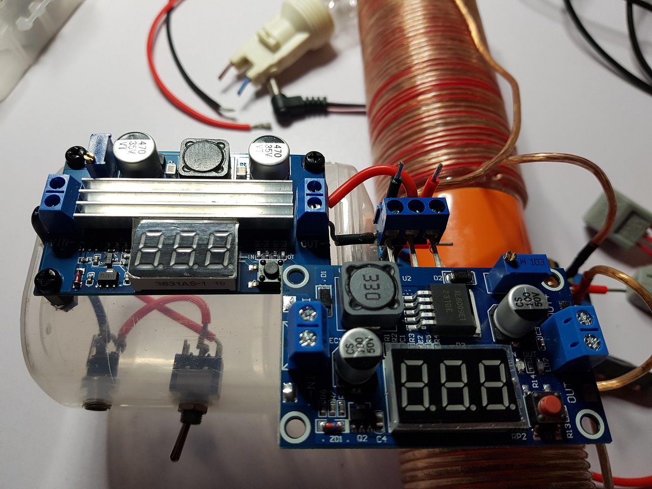
I mounted the new voltage booster in the weekend and I experimented with various experiments.
The Vpp in the coil at resonant frequency is not increasing proportionally to the new voltage as I expected, at 42.9 V the Vpp seems to decrease.
I need to experiment more to see if I can make the Vpp in coil to increase but so far I didn't succeeded.
But the good news is I found a configuration which seems to be super-efficient while still not affecting the input.
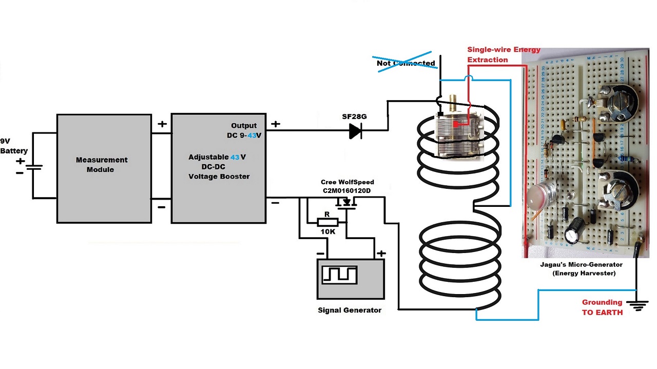
This is the schema of the previous configuration where I added with blue color the details of this new configuration:
Of course, just like I did with the previous experiment, I will prepare a video with all the details to show this new configuration and post it on my YouTube channel but as that will take some time until it will be ready I recorded a video for you showing this new configuration at work and the results:
The LEDs on output are now very bright and their luminosity is almost continuously and as you can see that extracted energy is still not affecting the input.
Now I'm pretty sure we're extracting about 22 mA (the consumption of the LEDs) and the input is still unaware of that energy extraction process.
This new experiment is another proof that what Don Smith told us is real:
It is found that creating a dipole and inserting capacitor plates at right angles to the current flow, allows magnetic waves to change back into useful electrical (coulombs) energy. Magnetic waves passing through the capacitor plates do not degrade and the full impact of the available energy is accessed. One, or as many sets of capacitor plates as is desired, may be used. Each set makes an exact copy of the full force and effect of the energy present in the magnetic waves. The originating source is not depleted of degraded as is common in conventional transformers.
Something else I just realized now, in this video I didn't recorded something important: the capacitance of the extraction module (the variable capacitor) is very important in the extraction process; the input is not affected by that capacitance at all (it's still "blind", not "seeing" the output), when I rotate the knob of the variable capacitor in one direction at maximum the LEDs' luminosity is at maximum (as you see in the video) but when I rotate the knob in the other direction at maximum the LEDs' luminosity is decreasing until it becomes 0.
Sorry, I didn't recorded this part in the video above but I'll keep in mind to include it in the YouTube video presentation of this configuration.
I'll try to find time (I have a lot of work to do at my job) to work on the detailed presentation video of this new experiment and when it will be ready I will post it on YouTube and also here just like I did for the previous experiment.
Even if I succeeded in proving what Don Smith told us in the quote above, I'll continue the experiments with this configuration.
Now the question is how much energy can be extracted while not affecting the input. As you can see in the video the new voltage booster itself is consuming about 81-82 mA. When we start pulsing the coil at resonance frequency the consumption increase to about 94 mA.
So right now with about 12 mA input in the coil we extract about 22 mA, this is already overunity and for sure there are ways to increase the actual COP.
I'm thinking about using Avramenko plug for collecting this energy in a capacitor as DC (I'll need one with low ESR) put in the place of the energy harvester and also to use a variable capacitor (or resistor) as Don Smith also told us.
I'll come with updates as I'll find time to continue the experiments.
Regards,
Fighter
"If you want to find the secrets of the universe, think in terms of
energy, frequency and
vibration."
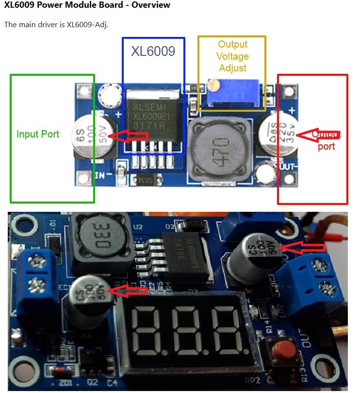
just a word about your buck boost converter XL6009 DC to DC, I just look spec for for your buck-boost converter and specs are:
Features and specification of XL6009 DC-DC Power module, Input voltage: 3 - 32V Output voltage: 5 - 35V (adjustable)% Output current: Maximum output current 4A Note: The higher the voltage, the load current increases. Efficiency of this regulator upto <94% Load regulation: 0.5% Voltage regulation: 0.5% Adjustable potentiometer onboard for output voltage adjustment. Non - isolated constant voltage module. Non - synchronous rectification. Short circuit proportion: current limiting since the recovery. Dimension: 45*20*14 mm (L*W*H)
If you check capacitor input and output rated at 50 maximim voltage rated this is normal output setup with 94% efficiency.
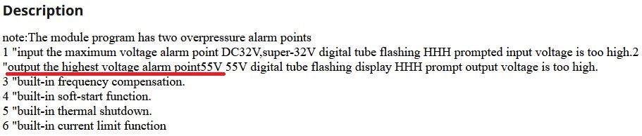
About the voltage booster, seems it had false advertising here:
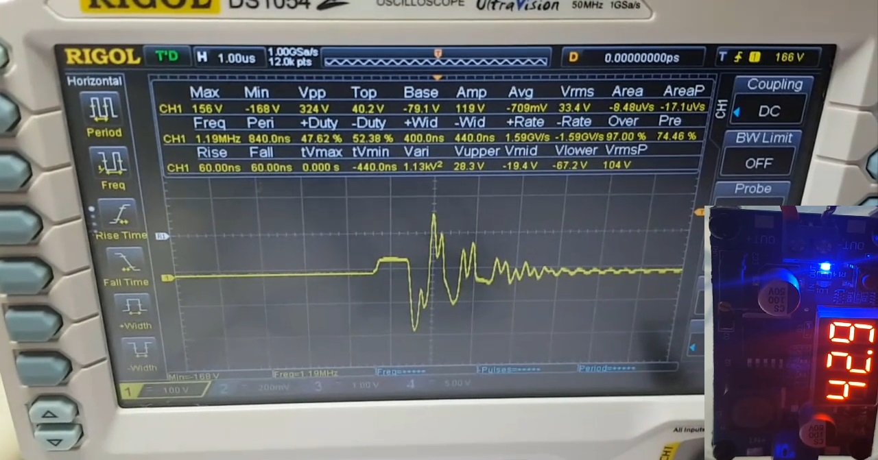
This explains the very strange waveform it produces in the coil, even if it shows 42.9 V output probably it can't sustain that voltage:
Probably the other two similar boosters I bought have the same problem so I'm gonna continue using this one but I'll decrease the voltage until it can sustain it and the waveform will start looking like the waveform in the previous experiment.
Still, I see a difference in the capacitors voltages, in the specs from your link it has 50V/35V while this one have 50V/50V:
The capacitor voltage on the output made me think this one really have 50V output but seems it doesn't.
But it's okay, the configuration I found in this experiment is still valid, the energy extraction is super-efficient while the input is still not affected.
Regards,
Fighter
"If you want to find the secrets of the universe, think in terms of
energy, frequency and
vibration."
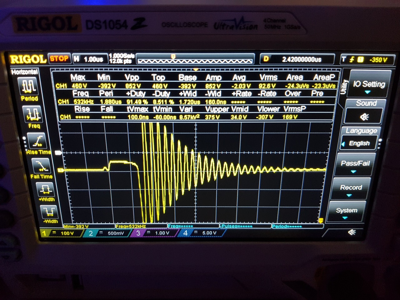
Seems the new voltage booster actually can sustain pulses of 42.9 V, the reason the waveform was distorted during the experiments was because of connecting the black wire from the variable capacitor to the middle of the big coil.
Without that the waveform looks okay and its Vpp is now reaching above 850 V.
Also I ran the experiments again in order to record all the videos needed to make a presentation video just like I did for the previous experiments here.
Building that video and adding all the information to it will require some work and I'll do it as I'll find time for it.
Regards,
Fighter
"If you want to find the secrets of the universe, think in terms of
energy, frequency and
vibration."
Hey Fighter, I know it's easier to come up with ideas, then to implement them, but have have you tried running the coils at it's resonant frequency(looks like ~530khz from the ringdown). Or with a series capacitor(will need more than 1 mosfet for this). Both will probably take a lot more current but will probably result in alot higher voltage. But along with setting a freq, you can then maybe match this with your capacitor inside the coils for better output....I know Don wasn't straight forward with his setups, but resonance was a key point he continuously made.
But the main reason for this post is to ask if your able to show the waveform on the capacitor inside the coils, i was curious of what was hitting the plates.
Great job BTW, looking forward to seeing your thread progress.
No worries, questions and ideas are welcome in all the threads on this site, it's part of the collaboration process between the members of our team.
Sorry for the late reply but I needed to find time to record 3 short videos with experiments at different frequencies and duty-cycles. As a image is better than 1000 words, a video is better than 100,000 the words and it can show more details and explain more than I can explain by just using words.
About the resonant frequency, I never start an experiment without making sure the coils of the device are working at their resonant frequenciey. It's my standard procedure I also used with ZPM and of course I'm using with this device.
All our devices are capable to show the effects we see only at resonant frequencies, in my opinion without resonance an experiment is kind of irrelevant as that device will not work at its peak performance/efficiency during the experiment.
The way I find the resonant frequency is by looking for the frequency where Vpp is at maximum. In the case of ZPM I also used the frequency-sweep procedure using a light-bulb then some fine-tuning arounf the frequency I found.
We also know that any component (resistor, capacitor, light-bulb, etc.) introduced in the circuit will change the resonant frequency of the coils so that new resonance frequency must be found. That's why everytime I changed the light-bulbs on the output of ZPM I always searched for the new resonant/optimal frequency.
About this device (should we name it DSE ?..), as far as I found for duty-cycle 1% and amp 9 (signal generator parameters) the resonance frequency is at 11 KHz.
At higher frequencies the Vpp will decrease so at 530 KHz it will go to almost 0. In order to have be able to still have the effect at that frequency range it is necessary to increase the duty-cycle from 1% to about 35% and that will dramatically increase the input current.
As I said I recorded 3 videos for posting them here so the members of our team can "feel" and understand better the behavior of DSE.
This is the test at 533 KHz, amp 9 V, duty-cycle 35%:
This is the test at 566 KHz, amp 9 V, duty-cycle 35%:
And this is a test at 6 KHz, amp 9 V, duty-cycle 1% just for comparison about the input current consumption:
As you can see at higher frequencies the consumption increases because, in my opinion, those are not the resonance frequencies of the big coil (remember, it's just a big coil composed from two identical CW coils, the two coils are not opposing each other).
In my opinion going to the direction of increasing the input current consumption is wrong, we should go with minimum current consumption on input while we still have the effect (input not affected by load) present. It's the same direction I followed with ZPM during development and experiments.
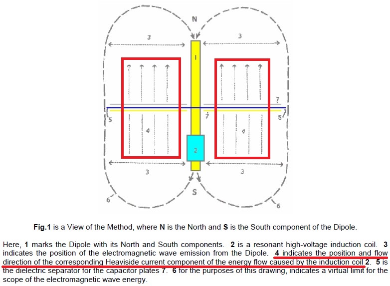
About what's hitting the plates, that is the Heaviside current component produced by the magnetic field of the coils, the one which (in my opinion) is capable of interacting with the zero-point field and provide energy without affecting the input.
More specific this (highlighted with red color in the image below):
I understand what you're asking for - the waveform produced in the variable capacitor, I'll come back with that information as soon as I find some time. The question is in what configuration you want me to show it ? There are 2 options:
The black wire of the variable capacitor is not connected (like in the experiments before this current configuration);
The black wire of the variable capacitor is connected to the middle of the big coil (like in the experiments with the current configuration).
For me I kind of measured the energy of that waveform indirectly by seeing the luminosity and frequency of the LEDs on the micro-generator placed on output but yeah, that waveform would be interesting to see too.
Thank you, as usually I'm trying to find time to continue the experiments but before that I'm trying to work on the presentation video (with explanations and details) just like I did for the previous configuration, the one you can see on my YouTube channel. Because this configuration is considerably more efficient than the previous one (the luminosity of the LEDs is increased and we're not exctracting pulses anymore, we're extracting almost continuous energy).
It's still much to explore with DSE (yeah, let's name it this way for convenience).
I plan to continue with Avramenko plug collecting this energy in a low ESR capacitor and to try to obtain DC on output and discharge it to an resistive light bulb to have proper output measurements.
Then I want to use a variable resistor/capacitor on the ground connection wire, the "dam of electrons" from the Earth as Don Smith named it.
Also, in the current configuration the energy extraction is almost continuous (not extracting just pulses anymore like we did in the previous configuration).
Considering the fact that we're already extracting about 22 mA, more than the coil is consuming (we should not include in the calculation the own consumption of the voltage booster, it can be replaced with a direct input of 43 V) seems DSE is already overunity.
Also considering the fact that we're extracting that energy from just a small part of the big coil (the length of one variable capacitor is about 3 cm while the total length of the wired part of the big coil is 24 cm) I'm wondering how much energy can be extracted if I put plates inside the entire length of the big coil. Like building two customized capacitors having each 12 cm length.
A very basic estimation tells me we can get about 22 mA x (24 / 3) = 176 mA and if this process will still continue to not affect the input we will still have about 20 mA consumption (without voltage booster's own consumption) which means we will have about 8.8 COP.
So if the plan and estimations will be proven to be coorect, at 8.8 COP it means DSE can easily become self-running while still providing about 150 mA output.
I know, it's a long shot about the plan and the estimations, but I intend to try to build those two customized capacitors and extract the entire available energy provided by this effect while not affecting the input.
And who knows what surprises a variable resistor/capacitor on the Earch connection will come with.
As I said, a lot of pending experiments and ideas, the only problem is as usually to fight to find the necessary time to continue. With the time taken by the daily job and so many other things to do (and they are not optional), probably the most time I'll find will be in the weekends and some chunks of time I can catch during the weeks... 🙂
But I'll continue as I find time and I'll come with updates here.
Regards,
Fighter
"If you want to find the secrets of the universe, think in terms of
energy, frequency and
vibration."
Hey Fighter, thank you for the demonstration. Initially I meant just the capacitor connected to the scope without anything else, to see those waveforms. But option 1 and 2 would be good to see.
Highest voltage doesn't necessarily mean resonance, it's true there is a resonant reaction between L and C, and this is observed at switch off, where all the energy stored during the pulse is released through the ring down between L and C, which is at Fr.
Though from what I can tell by the distortion at higher frequencies there may not be sufficient coupling between the coils at the voltage your driving it at, or others things contributing to the distortion.
I would recommend trying to drive the coils through a H-Bridge, it should better isolate them....I may be wrong.
Highest voltage doesn't necessarily mean resonance
I understand what you are saying but I think we are talking about different things.
What you are referring to is the resonance frequency of the coil without any other components connected to it. I can find that too using the method specified here where I checked the ZPM's coils.
But keep in mind the resonance frequency is changing when we have other components connected to the coil. Like it's hapening within DSE or ZPM, the resonance/optimal frequency is different when the coil is part of a circuit with capacitance and resistance and the way I find it is by looking for the highest Vpp or to observe the luminosity of some light bulbs (or in this case LEDs) on the output.
That's the resonance frequency I'm interested in when doing experiments, as an example please check the video below:
As I presented in the videos from my previous post, at 533 KHz we have no waveform in the coil unless we increase the duty-cycle to 35% which means dramatic increase of the input.
And that's not the way i want to go. I want to have the coil working in resonance mode (meaning highest efficiency on output) with all the components around for 42.9 V and the minimum duty-cycle of 1%. And that resonance frequency in these conditions seems to be at about 11 KHz.
About the distortion, that's only present when I connect the black wire of the variable capacitor to the middle of the big coil. Without that there is not distortion as I specified in this post above.
So there is no reason to change the current way I do the switching, I consider it okay.
initially I meant just the capacitor connected to the scope without anything else, to see those waveforms. But option 1 and 2 would be good to see.
Okay, I'll try to find time to get scope images of the waveforms in the variable capacitor in all 3 scenarios. During these tests I'll look for the value of the variable capacitor which will provide the highest output, meaning LEDs luminosity.
And I was thinking about the previous post and I want to come with a clarification about the DSE ebing already overunity even if we're gathering the energy from just a small region of the coil:
Considering the fact that we're already extracting about 22 mA, more than the coil is consuming (we should not include in the calculation the own consumption of the voltage booster, it can be replaced with a direct input of 43 V) seems DSE is already overunity.
What I meant to say is in the current experiments the voltage booster is consuming on its own (without any load on its output when the signal generator is off) about 81 mA just to convert the 9 V from the rechargeable battery to 42.9 V (the consumption will be lower if we choose to go with lover voltage in other experiments); well those 81 mA should not be included in the COP calculation as there are ways to provide directly 42.9 V without losing those 81 mA in the voltage boosting process.
The experiments will have the same results if, let's suppose, we would have a battery providing directly 42.9 V. In that scenario the consumption would be 0 mA (not 81 mA like we have now) when the signal generator is off and there are no pulses sent to the coil.
But because DSE is an experimental device, for now we prefer to unnecessary lose some input power just to have the benefit/flexibility to experiment with different voltages which the voltage booster can provide. But, as I said, the voltage booster's own consumption should not be included in the COP estimations.
I'll come with updates about the waveforms in the variable capacitor as soon as I can find some time.
Regards,
Fighter
"If you want to find the secrets of the universe, think in terms of
energy, frequency and
vibration."