The Don Smith Effect

  • 8.3K Views
  • Last Post 4 days ago
Fighter posted this 28 May 2023

In order to not interfere with Jagau's experiments with Dr. Stiffler's SEC technology which have many things in common with what Don Smith named "The Don Smith Effect" I'm starting in parallel with Jagau my own experiments with Don Smith's tech.

If this experiment is successful maybe we can unify the technologies these two great teachers demonstrated to us.

So below is my first post in this related thread here.

Fighter

"If you want to find the secrets of the universe, think in terms of energy, frequency and vibration."
Nikola Tesla
Fighter posted this 07 September 2023

I'm adding this video here, Gandalf found it and sent it to me.


It's the classical Don Smith experimental device using a plasma globe (created by basically a Tesla mini-coil) like in the second post of this thread, just the researcher added another experimental part containing a permanent magnet and a coil on top of the plasma globe.

Very inspiring, thanks Gandalf !

In the weekend I will continue with the construction of my experimental device and I'll post updates here.

Regards,

Fighter

"If you want to find the secrets of the universe, think in terms of energy, frequency and vibration."
Nikola Tesla
Jagau posted this 08 September 2023

 Hi everyone
Listened to John Bedini explaining on the board where the Energy of the universe comes from 15.08 until 17 min    Very interesting

https://www.youtube.com/watch?v=wprK-cwXLig&t=908

Don Smith often speaks of bloch wall, look at double cones and how he explain it, dont forget Bedini is a electronics engineer

Energy comes this way

 Jagau

Fighter posted this 09 September 2023

Replying To: Jagau

You're right, this is how our machines are gathering the zero-point energy.

As a completion to your post this is one of my videos showing similarities between John Bedini's explanation and ZPM's functionality (especially at 7:33 in the video):


Fighter

"If you want to find the secrets of the universe, think in terms of energy, frequency and vibration."
Nikola Tesla
andy2 posted this 09 September 2023

Hi all, because this thread is about DSE I will try to post question here.

I have found some documents about Don Smith devices including info about DSE 
https://archive.org/details/@energenius

I am currently making some experiments regarding to DSE with capacitors.
Because of safety I use only relative low voltages (I want to start HV after I make some progress with experiments).
I am not 100% sure, but I think I observe that capacitor (which is the main part of DSE) is working just as Don Smith described it.
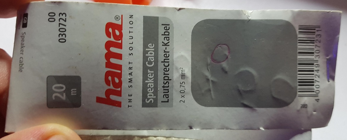
I use polarized electrolytic capacitor. On the first plate (plus) of capacitor (#1 - 2200uF 35V) is coming rectified high frequency (20kHz or 30kHz) voltage pulses about 100V (pulses come from 12V battery via wattmeter +ZVS + ferrite core coils).
The second plate (minus) is not connected to the input circuit, but instead via separated circuit (with some rectifier diodes and another capacitor (#2 2uF 50V) connected to separate grounding. 

(I use ultra fast switching diodes). 


I am able to charge capacitor #2 very fast to 120V (independently of the capacitor #1 which can be charged just only to 10V in that moment). If I short #2 it little bit sparks, discharges and charges again very fast. And on input measuring

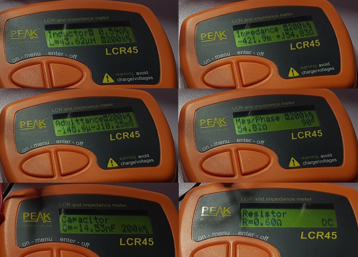
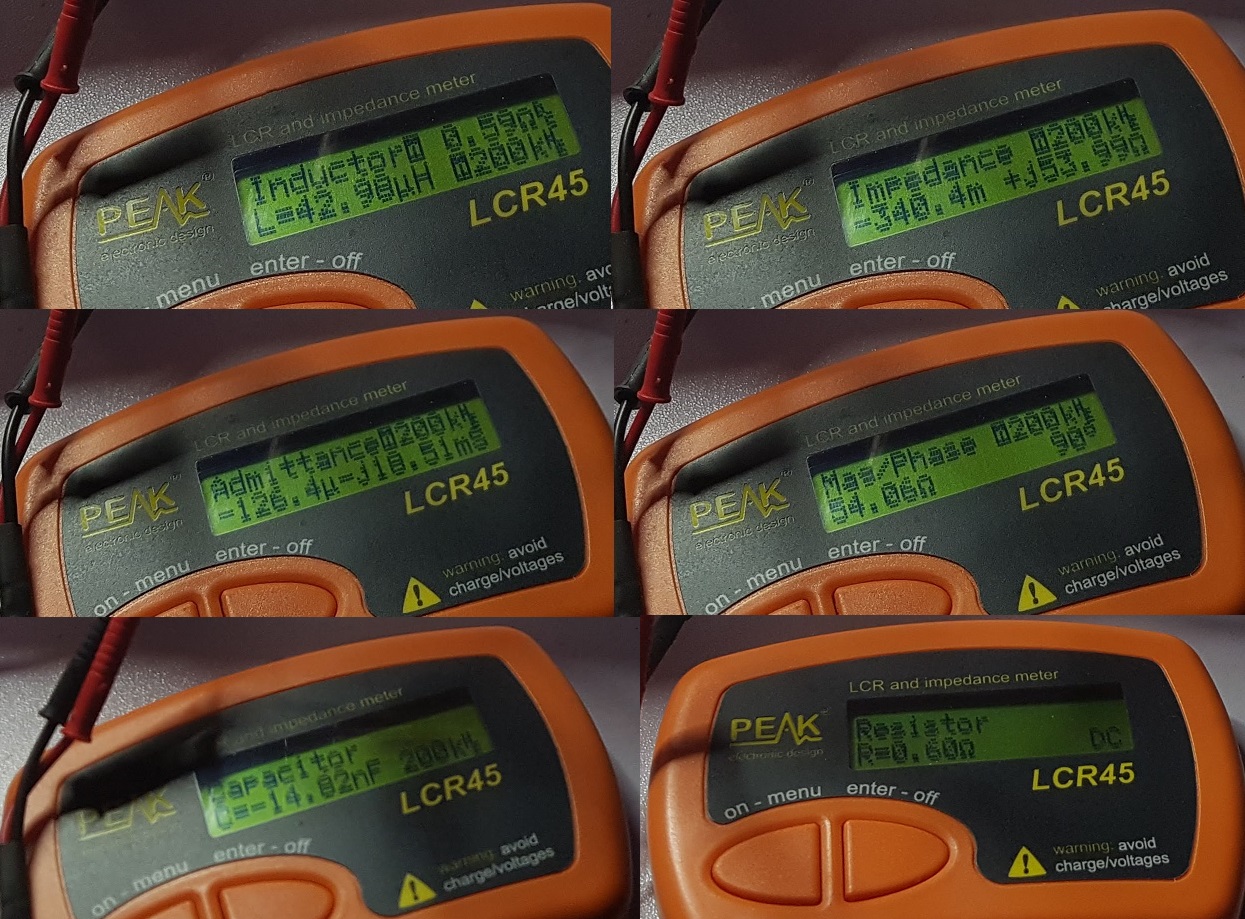
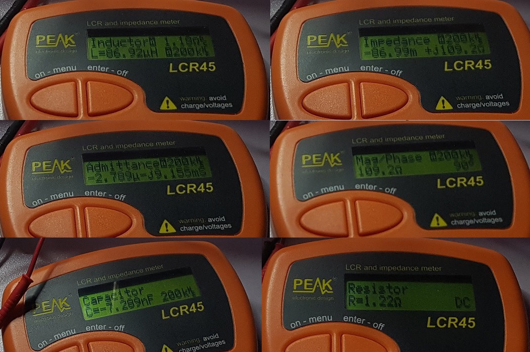
I am trying different capacitors like 2uF 50V, 2200uF 35V, 4.7uF 25V, 1000uF 25v

So I made "output" circuit accross the capacitor #2 with output ferrite core. So when I short this capacitor, current goes throught the core's primary and on the secondary I see almost nothing. So am struggling with some real (at least small) output.

Here I need help. What is wrong with this output circuit - why nothing (no energy) is seen here? 


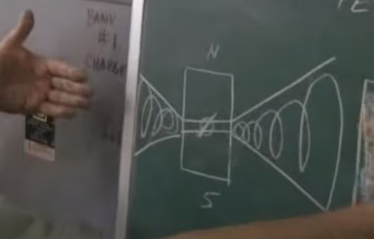
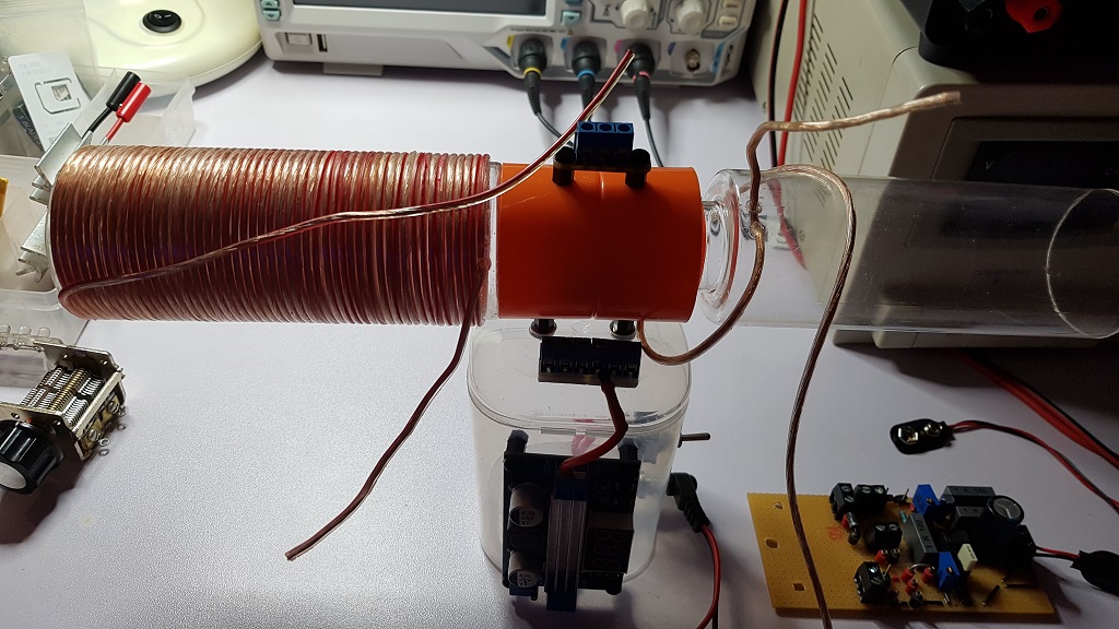
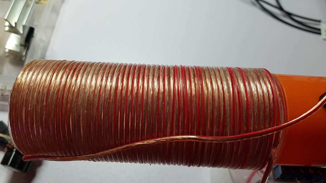
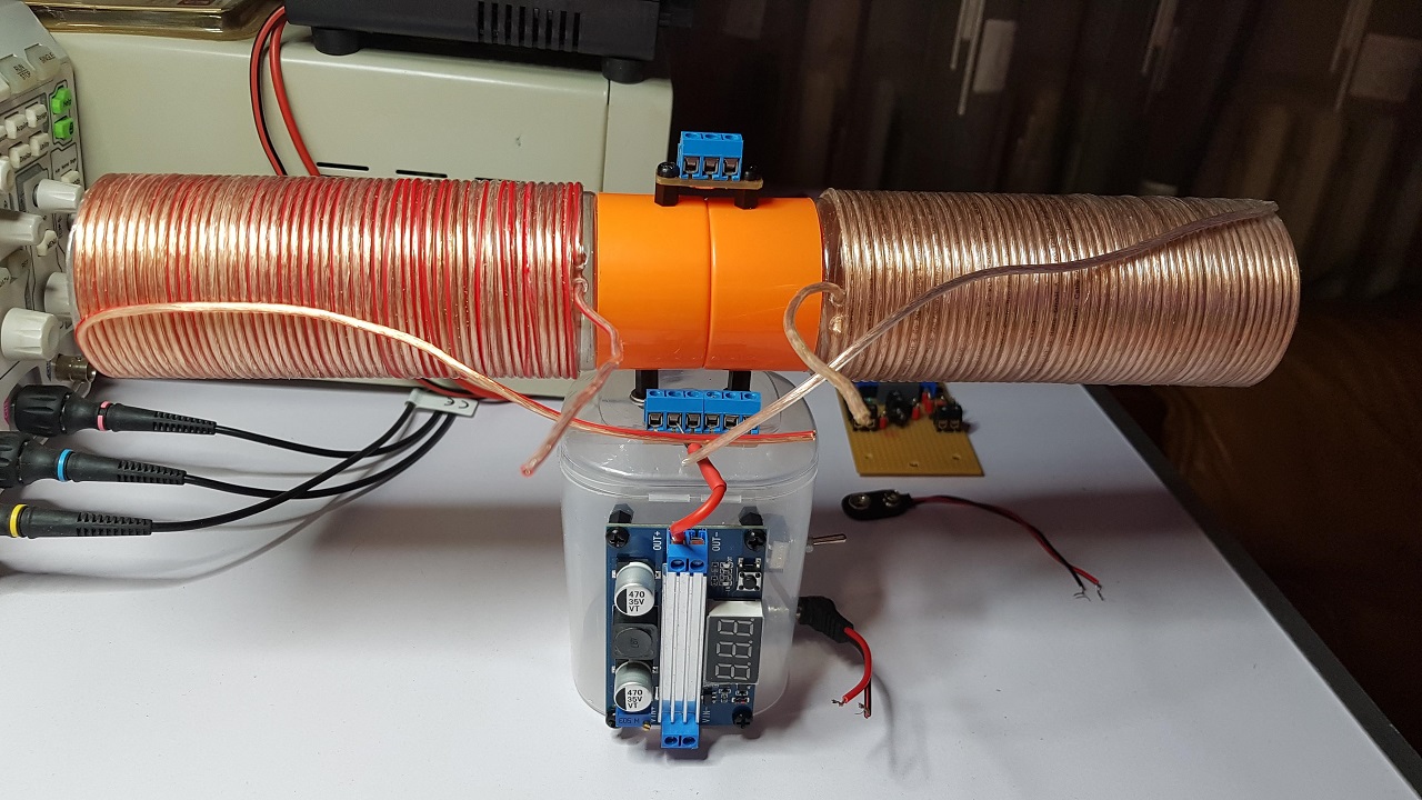
My setup is like in image (input part circuit not displayed here, only incoming pulses):


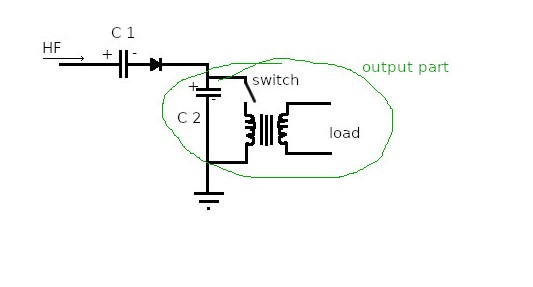
I thinkg/guess another results can be obtained with high voltage (above 2000 V) and adequate capacitors and the circuit can behave differently, but I am not ready to go this way

Andy


Fighter posted this 09 September 2023

Hi Andy,

Thanks for the link, I didn't knew about that archive.

I also don't intend to use high voltages in this experiment and I don't intend to go to that way. At this point I do believe the effect can be obtained without using high voltages.

What I would do is I would use an oscilloscope on the primary of the transformer to see what voltage and what current is in the pulses there. The fact that there is no power on transformer's output means the primary is not creating variable magnetic field for some reason else there would be power in the secondary coil.

What I don't understand is how are you using electrolytic capacitors for this experiment ? Don Smith says the plates of the capacitor should be perpendicular to the input coil and he is also showing non-polarized capacitors only in his drawings.

My suggestion would be to create a new thread with your experiment where you can present photos and schemas of your experiment and also how it's progressing. Just like I did here.

This way we can have a complete image of your experiment and our members here can help for sure because we have a very good team of experimenters here with experience in physics and electronics.

Another reason for creating the new thread is to not mix the information of our experiments and create confusion when presenting the data and asking for suggestions.

If you need help or have questions about creating your new thread just let me know.

Regards,

Fighter

"If you want to find the secrets of the universe, think in terms of energy, frequency and vibration."
Nikola Tesla
Fighter posted this 12 September 2023

In the weekend I will continue with the construction of my experimental device and I'll post updates here.

Well, I didn't had the time as I planned, I'll try to work on it during this week as I'll find some time.

Sorry about that.

Regards,

Fighter

"If you want to find the secrets of the universe, think in terms of energy, frequency and vibration."
Nikola Tesla
Fighter posted this 18 September 2023

This weekend I've got some available time so I've built the two halves of the coil:

I needed to take precise measurements to make sure the two halves of the coil are (as much as possible) identical so they have identical natural resonance frequency.

That will be very useful later as I'll use them in multiple scenarios as Don Smith shown to us.

Keep in mind they're part of the same coil (no opposing magnetic fields) and their winding is the same: CW (clockwise).

As it's very late here and tomorrow I have work I'll comeback with more details about their construction, specs and of course measurements (resistance, capacitance and resonance frequency).

Hopefully these measurements will show identical numbers or as close as possible (considering the fact that I've done the windings manually).

We'll see...

Regards,

Fighter

"If you want to find the secrets of the universe, think in terms of energy, frequency and vibration."
Nikola Tesla
Fighter posted this 21 September 2023

Found some time to make coils measurements and organize the information for posting it here.

So here are the details.

I used the wires from an  2 x 0.75 mm2, 20 meters length speaker cable I bought from here.

This is the label of this type of cable showing more details:

I splitted the two wires of the cable then I temporary wired a coil on one of the transparent coil supports to measure how many turns a half of the coil could have considering the length of one of the coil supports.

Turned out that each half of coil should have exactly 8.75 meters and 50 turns. So these are the physical specs of the two halves of the coil.

I've made the measurements with my LCR meter for: left half of the coil, right half of the coil and the full coil.

As the photos of the measurements are too many I'm not gonna post them here but I'm attaching a archive to this post containing the original high resolution photos.

Here I'm gonna post summaries of the readings from my LCR meter (set to make measurements at 200 KHz). 

So here they are.

  • For the left half of the coil:

  • For the right half of the coil:

  • For the full coil:

So we have:

  • Left half of the coil: wire length 8.75 m, inductance 43.62 µH, capacitance 14.53 nF, resistance 0.60 Ω;
  • Right half of the coil: wire length 8.75 m, inductance 42.98 µH, capacitance 14.82 nF, resistance 0.60 Ω;
  • Full coil: wire length 17.50 m, inductance 86.92 µH, capacitance 7.289 nF, resistance 1.22 Ω.

As the measurements are showing physically and electrically the two halves of the coil are almost identical (considering the fact that I've built them manually) so their natural resonance frequency should be the the same just the way I intended.

When I'll find time I'll set up the testing experiment in order to find their natural resonance frequency and I'll post the details here.

For now I just added this info here, it will be very useful later during the coming experiments.

Regards,

Fighter

"If you want to find the secrets of the universe, think in terms of energy, frequency and vibration."
Nikola Tesla

Attached Files

luwanbing posted this 08 October 2023

Replying To: Jagau

Thank you so much for your Don Smith Tribute pdf
Send one's regards to
Lu Wanbing from China

Jagau posted this 11 October 2023

Hi Luwanbing

We will appreciate your comments on Don Smith's experiences.

You are welcome here.

Jagau

Close