The Don Smith Effect

  • 8.3K Views
  • Last Post 4 days ago
Fighter posted this 28 May 2023

In order to not interfere with Jagau's experiments with Dr. Stiffler's SEC technology which have many things in common with what Don Smith named "The Don Smith Effect" I'm starting in parallel with Jagau my own experiments with Don Smith's tech.

If this experiment is successful maybe we can unify the technologies these two great teachers demonstrated to us.

So below is my first post in this related thread here.

Fighter

"If you want to find the secrets of the universe, think in terms of energy, frequency and vibration."
Nikola Tesla
Jagau posted this 18 October 2023

Don't forget John Bedini's explanation on the representation of the magnet /coils and where Aether flow comes from, the Don Smith effect can easily be compared to this explanation.

Another photo which is worth a thousand words in the explanation of its invention. Look to the left at the Aether flow entering the magnets / coils, the scalar earth.


Jagau

Fighter posted this 18 October 2023

Thanks, yes, I didn't forgot:

The above image is from this video I have on my channel:

These two coils are identical, should have the same natural resonance frequency and they are basically forming a single coil (they are not opposing each other):

So the Bloch wall should be there in the middle gap and in that zone it's possible we could find interesting effects of the zero-point energy entering in the system.

But this would be another experiment after the experiment with the variable capacitors placed inside the coils.

That's why I've built this device modular with interchangeable coils and able to support different configurations, because I wanted it to be a platform for multiple experiments.

For example the platform could easily be adapted to support other Don Smith's experiments like these:

Even if I didn't found too much time to work on it lately I will continue as I find time.

Fighter

"If you want to find the secrets of the universe, think in terms of energy, frequency and vibration."
Nikola Tesla
Fighter posted this 19 October 2023

Hi Inception,

Yes I know Rick Friedrich's demonstrations.

This guy recorded and posted on his channel all Don Smith's public demonstrations and dedicated his entire effort to clarify and share Don Smith's technologies.

I didn't knew he still have for sale these kits. Right now the page shows a error, I'll check it when it gets fixed.

But it's okay, I think I'll be able to reproduce that experiment with my modular platform.

Thanks,

Fighter

"If you want to find the secrets of the universe, think in terms of energy, frequency and vibration."
Nikola Tesla
Shelfordella posted this 20 October 2023

Lately I was thinking about the radio transmitter/receiver analogy, it didn't make sense, because the power received is mWatts and when received, it is no more in the air, the transmitting power is 100's KWatts. He also said opamp are a free energy device. You can't receive more than is transmitted, but the transmitted energy in Don's device is something else. The voltage-current relationship is based on this and nothing mysterious, but it is relative to 0v: https://tayloredge.com/reference/Machines/TeslaCoil.pdf


"A little theory and calculation would have saved Edison 90 per cent of the labor." Nikola Tesla

Fighter posted this 20 October 2023

Replying To: Shelfordella

That's because you still think about the radio as a closed system like all the other things they taught us in school. Don't get me wrong, all of us were taught this way and it's very hard to get rid of these concepts of the "official" science. Those concepts are just partial truth.

Closed symmetrical systems are fine and are working but they will never be overunity. Because they are not allowing external energy to be collected and used. They're just output = input minus losses. And that's all they taught us in school and told us there is nothing else possible.

On the other hand they never told us about the asymmetrical open systems where output = input plus energy gathered from the environment (aether / zero-pint / quantum field) minus losses. And these systems will almost always (depending on their method and effciency to gather energy from that field) be overunity. 

They taught us in school that Maxwell's equations are not allowing anything to be overunity but they "forgot" to tell us those are not the original Maxwell's equations but just a small subset of them "extracted" by Heaviside from the original equations just for the symmetric closed systems. And the original equations are allowing the existance of the asymmetric open systems.

The reason they did this ? Easy to understand, overunity systems would destroy the multi-trillion profits made every year by the Big-Oil energy cartels in the last 100 years.

The truth is, as Don Smith taught us, not a single electron is transferred from the radio antenna to the antennas of the radio receivers.

If you place 10,000 radio receptors around a radio station the input power consumption of the station will not increase even with a single miliwatt.

What the antenna of a radio station is doing is to create ripples in the aether / zero-point / quantum field, however you want to call it. The only reason for the need to increase the power of a radio station is not to accomodate with more radio receivers but to extend its range/radius, to create bigger ripples so it can be received at bigger distance.

What the antenna of a radio receiver does is to "feel" those ripples and replicate the same waveform but it does that without consuming even a single electron from the power station's antenna.

Just in my opinion:

  • The law of conservation of energy is a consequence (not the cause) of symmetric interaction in closed systems;
  • All open asymmetric systems are outside the region specified in the law of conservation of energy;
  • The law of conservation of energy cannot be violated BUT the scope of applicability of the law is only for closed symmetric systems.

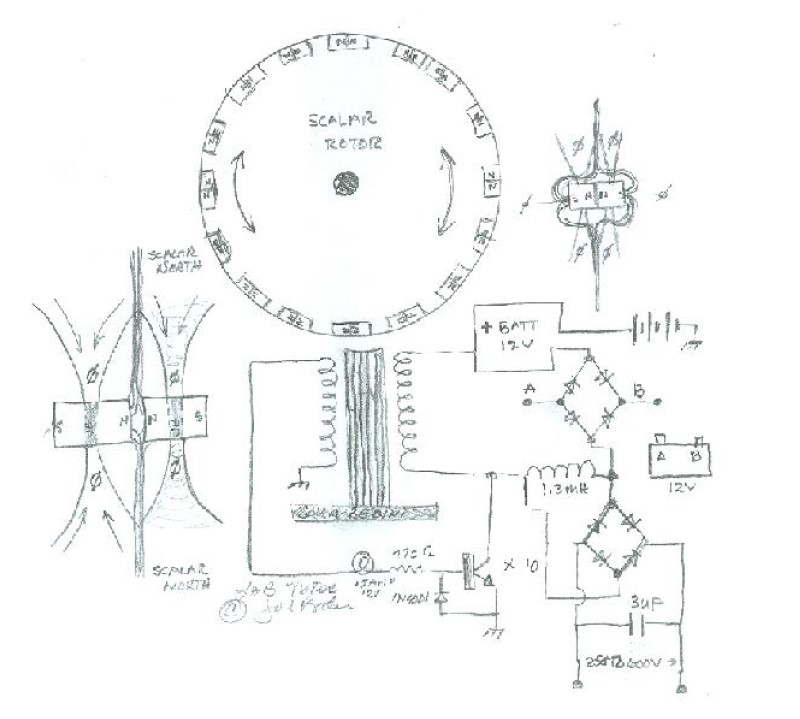
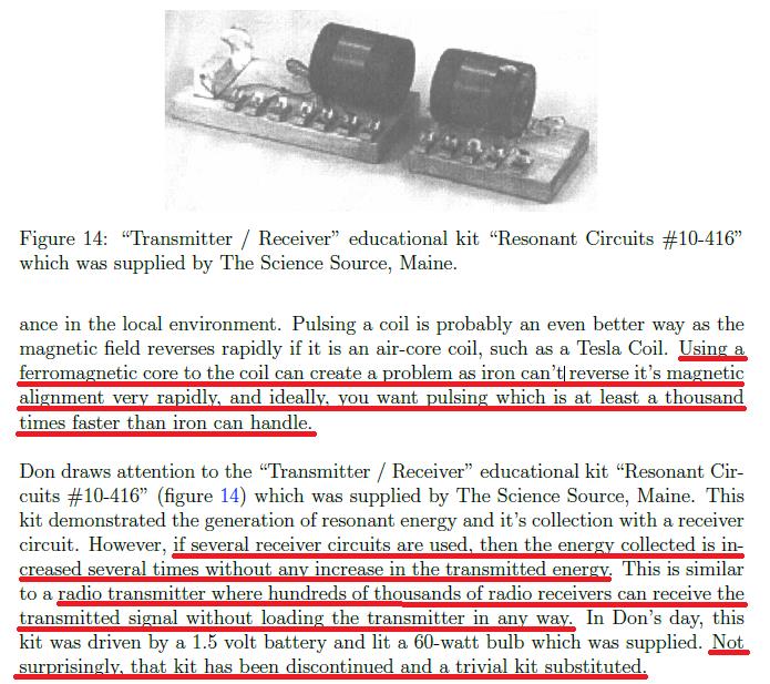
Don Smith's coils are actually antennas:

Each set makes an exact copy of the full force and effect of the energy present in the magnetic waves. The originating source is not depleted of degraded as is common in conventional transformers.

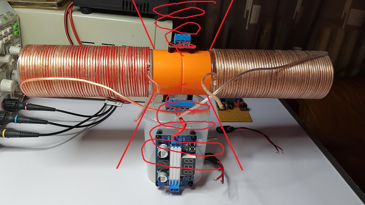
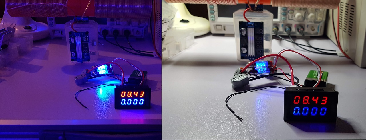
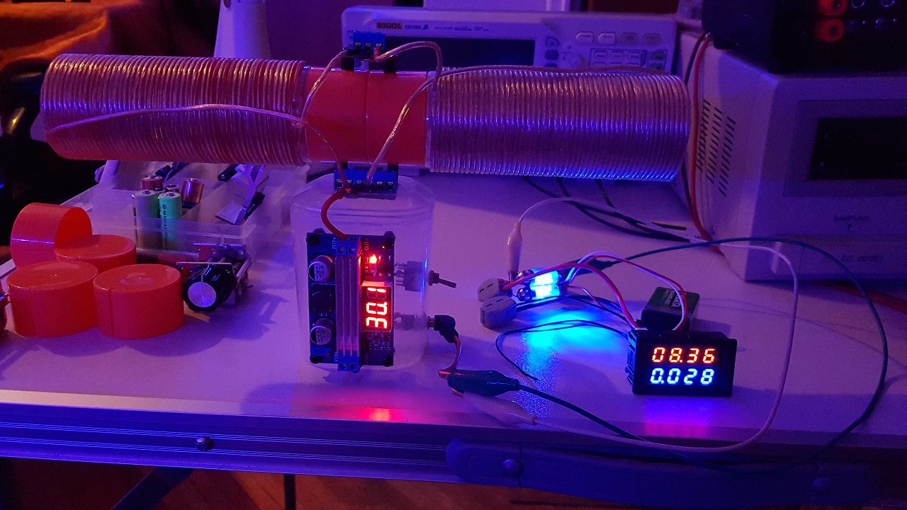
That's the purpose of the experiments I'm gonna do here with this experimental platform: to demonstrate that the consumption is not increased when placing 2, 3 or 4 variable capacitors (probably tuned to a certain capacitance) having their plates perpendicular on the coil's magnetic field and using in some loads the energy they're collecting.

A second planned experiment is to use the first half of the coil as input and to demonstrate the input is not increasing when using the second half of the coil as output to some load. That phenomenon should manifest when the two (almost) identical coils will work at their natural resonance frequency.

We'll see how the experiments goes and if there are other conditions/requirements necessary to demonstrate these principles.

Regards,

Fighter

"If you want to find the secrets of the universe, think in terms of energy, frequency and vibration."
Nikola Tesla
Fighter posted this 29 October 2023

Finally found a few hours to continue working on the project.

Evaluated the behavior of the measurement part using this ammeter.

For later references I'm adding the details and evaluation results here.

This is how it can be used:

I'm using it in common (shared) source mode.

Here it's measuring two LED lamps each containing 3 LEDs:

The current consumed by the LEDs is insignificant. Also it seems it's not displaying its own consumption and that's a good thing because that's not relevant in the incoming experiments.

Here I enforced high consumption by adding one 12V/10W halogen lamp:

It's showing 4.6 W consumption which is kind of matching light bulb's luminosity.

And here it's measuring the consumption of the voltage booster:

So the voltage booster alone (without any load on its output) seems to consume 0.23 W for 30 V.

I have a question related to the protection of the voltage booster's output.

As I specified in one of my previous posts on the plus of voltage booster's output I have a SF28G super-fast diode for protection against BEMF coming from the coil(s):

On the minus of voltage booster's output I'm gonna place a MOSFET as a high frequency switcher.

Is there a risk of damaging voltage booster's output because of the high-frequency load (meaning the coil) ?

Should I add more protection for voltage booster's ouptut ? Maybe a electrolytic capacitor in paralel with the output ? Or the super-fast diode on the plus is enough ?

Thanks for your opinions about this possible issue.

I'll continue with the construction of the device as I'll find more time.

Regards,

Fighter

"If you want to find the secrets of the universe, think in terms of energy, frequency and vibration."
Nikola Tesla
Jagau posted this 30 October 2023

Hi Fighter

Good clean work

For the first part at the beginning, it is normal that only the current is not displayed given that the current probe only reads the output current not that of the input so it does not display anything, only with a load you have a current displayed.

For the second part, I need you to make to me an electronic plan to better understand your question.

Jagau

AlteredUnity posted this 30 October 2023

Very nice and professional setup! I been meaning to protect my setup a bit more. I would recommend using a TVS, or a MOV, and maybe consider another external ground if available. If you know the frequency range you will be working with you can also use a snubber circuit with a resistor and capacitor though don't think that will be suitable for your application. And lastly maybe a flyback diode in parallel with your primary. Not too advanced with these configurations but it may help...

Fighter posted this 30 October 2023

Thank you guys !

As 3D printing would've required a lot of time (and some money) for designing and to send to a company for printing, I preferred to use what I had available here (like plastic bottles and boxes) and adapted them as needed... 🙂

@AlteredUnity

I'm posting below the schema I have in mind for clarifications.

Yes, I have a SF28G super-fast diode protecting the ouptut of the voltage booster against BEMF coming from the coil(s).

The frequency (and duty-cycle when using the signal generator) will be adjustable, I'll need to make frequency-sweeping during the experiments. Then when I'll find optimal or interesting frequencies I will use Jagau's Square Wave Oscillator Off-Grid set for those frequencies.

The entire experiment is designed to be isolated from the grid, that's why I'm using the 9V battery as input. Occasionally I will want to check what is the effect of a ground connection ("the source of electrons" as Don Smith named it) so I'll use for that a wire connected to the grounding of the power grid just like I use with my replica of Jagau's Micro-Generator.

@Jagau

You're right, I need to clarify what I have in mind and my question.

First, I didn't posted the specs of the voltage booster, it's this one on the site of the store I've bought it from.

And the schema I have in mind for the experiments is this one (I drew it by hand, sorry about that):

So as you can see there is a super-fast diode intended to protect the voltage booster's output against the BEMF produced by the coil(s).

I'm doing that because I'm not sure if the voltage booster was designed to support high-frequency pulsed loads and I don't want to damage its output.

My first question is: is that diode enough for protection ? Or should I also add an electrolytic capacitor in parallel with voltage booster's output for more protection ? Just like the one drawn with red color and having a question mark near it.

If I'm gonna need to use an electrolytic capacitor there it should have a fixed voltage (30V) so in that case I'm gonna lose the advantage of voltage booster's adjustable voltage. Basically the high-frequency pulses received by the coil(s) will always have 30V (just like the electrolytic capacitor) no matter what voltage I'm setting in the voltage booster.

Hopefully the diode is enough to protect the voltage booster and the electrolytic capacitor is not needed. That way I will keep the advantage of adjustable voltage of the pulses I can send to the coil(s).

I don't know how well I explained, if there is something not clear please feel free to ask.

Thanks,

Fighter

"If you want to find the secrets of the universe, think in terms of energy, frequency and vibration."
Nikola Tesla
Close