AlteredUnity's successful ZPM replication

  • 3.7K Views
  • Last Post 23 October 2023
  • Topic Is Solved
AlteredUnity posted this 16 January 2023

Hey everyone, im glad you started a new community, its a shame your device went from "should be first device to replicate after Non-inductive coil" to a toy, to deleted.

300Turn coil : measurements were made with both coils on center of core at 1khz; Coils were then put at far opposite ends of top and bottom of core.

20awg;  L = 425mH; DCR = 1.73 ohms

150Turn coil : 20awg; L = 110.7mH; DCR = 0.818 ohms

This is a fast trial run, have more to come with some ideas that may improve opperation. With this configureation I still pull 7 watts of power, so there isn't a whole lot of feedback. 

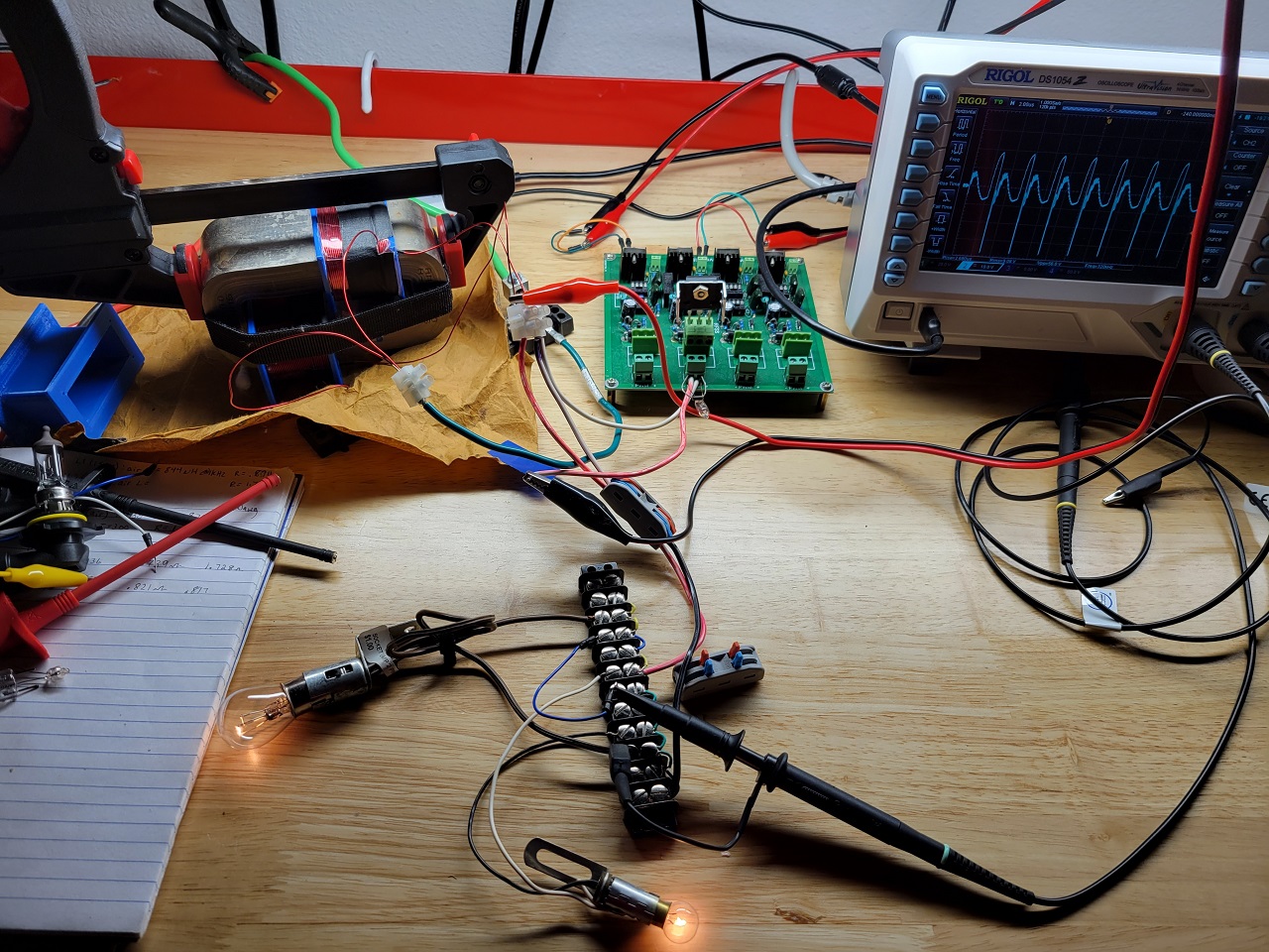
The center tap is connected to cable running to my cars body ground; The scope is connected across load, with its ground on the DRAIN of mosfet. This may be the wrong configuration and reason for not lowering input.

Any pointers are appreciated.

Attached Files

Order By: Standard | Newest | Votes
AlteredUnity posted this 16 January 2023

Hey everyone, im glad you started a new community, its a shame your device went from "should be first device to replicate after Non-inductive coil" to a toy, to deleted.

300Turn coil : measurements were made with both coils on center of core at 1khz; Coils were then put at far opposite ends of top and bottom of core.

20awg;  L = 425mH; DCR = 1.73 ohms

150Turn coil : 20awg; L = 110.7mH; DCR = 0.818 ohms

This is a fast trial run, have more to come with some ideas that may improve opperation. With this configureation I still pull 7 watts of power, so there isn't a whole lot of feedback. 

The center tap is connected to cable running to my cars body ground; The scope is connected across load, with its ground on the DRAIN of mosfet. This may be the wrong configuration and reason for not lowering input.

Any pointers are appreciated.

Attached Files

Fighter posted this 16 January 2023

Hello AlteredUnity and welcome,

Hey everyone, im glad you started a new community, its a shame your device went from "should be first device to replicate after Non-inductive coil" to a toy, to deleted.

Well, there are a very few rational things remaining on the old aboveunity site and there is almost zero real research since we left. The old site is basically dead in the water since then.

We needed to build our new home after that mentally-ill guy started attacking the members of his own team using false accusations and invented reasons, as everyone can see since we left the old aboveunity site became a place of paranoia, lies, disinformation, an religious-like cult with its wannabe cult leader banning "infidels" and preaching the "Bible" of the so-called partnered output coils which is a road going nowhere. What he doesn't realize is the only ones who kept his site advancing and being in top are us, the entire core team of researchers which are now here. You'll find here the entire core team of researchers, former aboveunity members, which are continuing their research and their experiments here.

You can find more details about all these in our public replies (with solid evidences) to his lies and and his false accusations against us here, there are harsh but well deserved words in our replies but the most important there are the proofs we present.

About the deleted ZPM threads, I'll import them in our site as I find time but it will take a while as there is a lot of experiments, tests and data in these threads. Until it's done everyone can download and use the backup archive with the ZPM threads here.

I wasn't aware you're experimenting with ZPM, I'm glad about it, who knows how many researchers are experimenting and replicated it without going public with their replications ?..

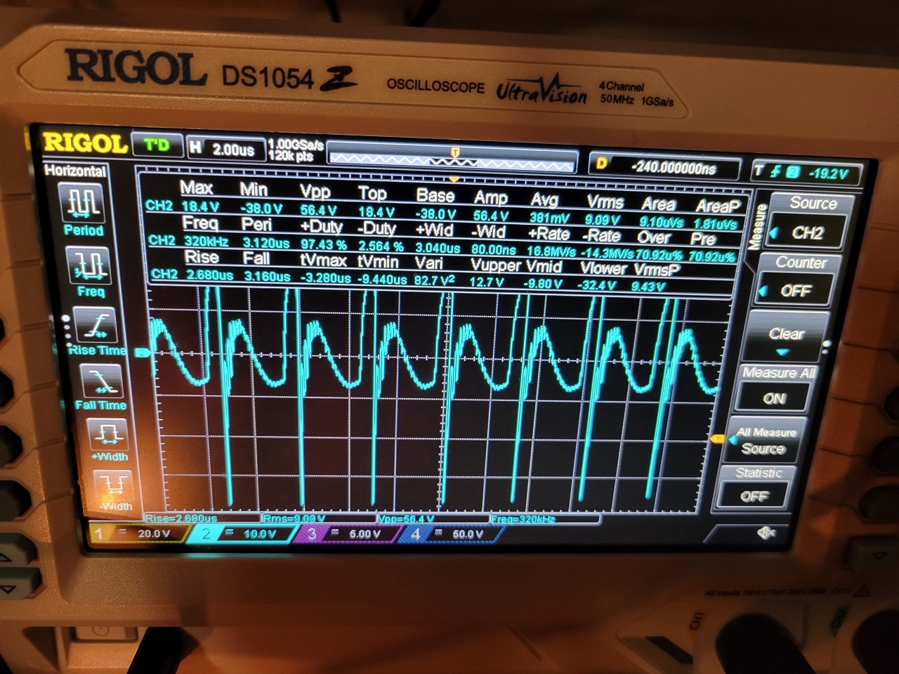
You have a very nice and clean setup there. I see your already have the very familiar ZPM waveform pattern so that tells me you're on the right track with your ZPM replication.

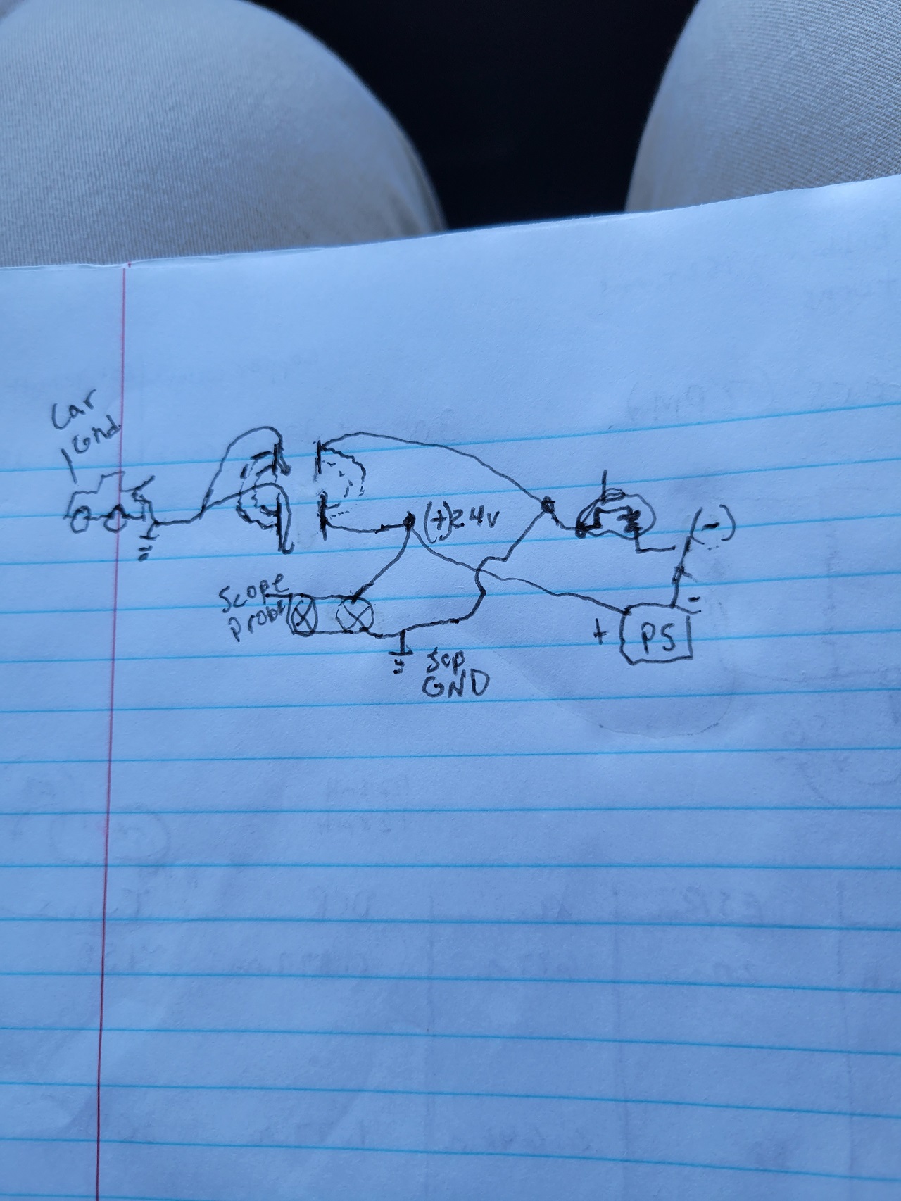
So you don't have the input decreasing effect yet ? Could you present an electronic scheme of how everything is connected in your replication ? Is there a ground connection ? If yes add it to the scheme too.

Since I shown my two ZPMs functioning (the prototype and a replication) there are another three successful ZPM replications: one kept secret for about one year by Chris (you'll find it in the backup archive I specified above) and two new public replications here on our site presented by Atti and Jagau.

So let's try to figure out the cause why the input decreassing effect is not present yet.

Regards,

Fighter

"If you want to find the secrets of the universe, think in terms of energy, frequency and vibration."
Nikola Tesla
Jagau posted this 16 January 2023

Hey alteredunity, welcome

Very nice configuration, just for the purpose of mutual aid I have a question, what formula do you use to get 7 Watts at the input?

Jagau

AlteredUnity posted this 16 January 2023

Thanks for the replies, I am only going off what my power supply is saying when I said 7watts in. Yea took a while to get motivated to make coils, just finished smaller coil yesterday, before that I was using diff bobbin with 150turns, only 1 ground, and it blew my circuit breaker while tuning.(maybe a good sign lol.)
I will post circuit I used for above. I was thinking in order to get coils wire to equal 1/2 the length of the 300 turn I will need to resize the bobbin. Originally I was going to add a 3rd 1/4 turn coil as well. But if the time is taken to do that I wanna get all the wire lengths measured.(I feel like a matching wavelength and divisions of, your coils will probably interact even better.) The center tap is attached to my car for ground.

Fighter posted this 02 August 2023

Quoting:AlteredUnity

I was going to ask if the wires were hot when you touched them, but just read the thread when you posted about it, thats even more interesting.

I don't remember too many details about the experiment but it's a good thing I documented the results at that time. So the answer is yes:

Something I also noticed when suing 2 x 12V/35W light-bulbs on output, when using those connectors having crocodile-style terminals and small AWG (diameter), the connectors on output are becoming so hot until the plastic which isolates their wires is going to the point of starting to melt even if they don't have direct thermic contact with the halogen lights; in the same time the same type of connectors on input are cold, not  even warmer.

Here could be two possible explanations:

  • let's just suppose there is the same amperage on input and output, the output wires are being hot because of the very high frequency AC while the wires on input are cold because there is DC;
  • or the amperage on the output is much higher than the amperage on the input (as source's readings and the luminosity of the light-bulbs seems to indicate) meaning high COP.

Quoting:AlteredUnity

those I believe are fine stranded wires on those alligator clips, so may be combination of length and/or wire type.

I checked the electronics store where I bought them, they still have that kind of wires here.

Yes, they are 48 cm long (including the clips) stranded wires and what's more interesting is they support maximum 1A current. So what the experimental results were showing: input was under 1A (wires on input were cold) while output was over 1A (output wires became hot) which is obvious also from the luminosity of the 2 x 12V/35W halogen lamps on output.

That gives us also an idea about ZPM's overunity characteristics without using any measurement instruments.

Now looking back and having the new information you discovered about the wires I realize it was also a matter/percentage of luck: with longer/different wires I would have missed the input decreasing effect while I was trying different configurations during the development of ZPM...

Thanks,

Fighter

"If you want to find the secrets of the universe, think in terms of energy, frequency and vibration."
Nikola Tesla
Jagau posted this 16 January 2023

Remember that what your power supply tells you does not necessarily represent what the circuit consumes. Depending on the duty cycle this can be less than what the circuit actually consumes.
Simplest possible example with a linear resistor with 24 volts on a 10 ohm resistor pulsed at 50% your PS will indicate 26 watts of consumption of the 10 ohm resistor, which is not correct. The correct answer is 13 watts which can be verified in various ways with well-known formulas. The PS does not know the duty cycles, it does not know how to interpret them.
 
For an oscilloscope like you, the calculation is done in IRMS and Vrms, but if you do not have integrated software or purchased separately from your math menu, your oscilloscope cannot interpret the average power, you will not yet have the right answer, it will give you instant power
An oscilloscope without this software calculates the instantaneous power not the average power, don't worry I have the same problem with mine, that's why you have to use the standard formulas.

Jagau

Fighter posted this 25 March 2023

To be honest I don't care about naysayers. They gonna "sing" the same "song" even if you put a self-running device on their table.

Right now ZPM's circuitry (wires, connectors etc.) are in some boxes, I would need to find them and rebuild the circuitry. And I don't have time for that, hopefully soon I'll have some more time to continue with the experiments.

About the wattmeter, I tried that long time ago and it was inconclusive, it shown much more than the 60V/5A DC source can physically provide and the readings were jumping up and down. It was clear the power meter readings were messed up by ZPM. These things (power meters, standard hand-held non-contact measurement tools, standard multimeters) are made for 50/60 Hz to max. a few tens of KHz, not for hundreds of KHz where the ZPM is functioning.

Remember Editor's freezer being affected by ZPM ? If not check it here. I understood later why the power meter was affected even when placed on DC source's power cord.

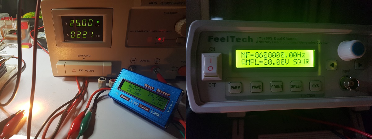
Still, I used an more advanced power meter which (I'm quoting from its specs): "Acts like a wire so doesn't affect model's performance. Precision Alu-Chrom current sensing resistor, with only 0.001Ohms resistance and circuitry that draws only 7mA Uses DSP to increase ADC resolution and differential measurement amplifiers to increase noise immunity. Powerful, 8MIPS micro-controller.". I "forced" ZPM out of the optimal/resonance frequency so the consumption would be higher because the wattmeter is not built to measure currents lower than 0.100 A. and it confirmed the DC source's readings:

The small current difference (~ 0.01A) is because the power meter itself have a small consumption.

The probability of ZPM messing the readings of two different devices (at the same ZPM frequency but with different components, different reading sensors, etc. ) but still the devices to show the same readings is the same as the probability to play at the lottery for the first time in life and win the big prize then playing for the second time and win the big prize again.

Technically and statistically the probability is 0.

You can see more details here and here.

On my side the constant decreasing of DC source's readings when getting close to ZPM's resonance/optimal point (and that point is different with different loads) is the proof of ZPM's overunity. And if the DC source's readings would be messed up the values would jump up and down with big differences, the increasing/decreasing of the readings would not be so smooth.

But I don't want to derail AlteredUnity's replication thread with a different subject. 

Regards,

Fighter

"If you want to find the secrets of the universe, think in terms of energy, frequency and vibration."
Nikola Tesla
cd_sharp posted this 25 March 2023

Guys,

I recommend everyone to have a look at this video and the other videos related to the subject on the same channel:

Yoelmicro pointed out from the beginning this relationship in the ZPM. We just had no idea what impedance matching is.

Stay strong!

If you know how to build such a device and you're not sharing, you're a schmuck! - Graham Gunderson

Jagau posted this 05 April 2023

Hi Alteredunity

I don't know how your project is going, we can't hear you.
Which circuit you used for your ZPM replication??

When you have understood how it works at the exit you will have a beyoudunity system like this one.


As here you have 4.04 watts average power at the output, see how bright the output lamp is.

With an instantaneous power input  of 4.33 watts converted into an average power of 2.5 watts input power.

Jagau


AlteredUnity posted this 06 April 2023

Replying To: Jagau

Thanks for checking up, I just moved my bench upstairs and organized my stuff, I'm hoping by this weekend I will have something to show. For the past few weeks I've just been working on running a normal dc switched load and normal transformer to get a feel of correct scaling etc on oscilloscope to be sure I'm getting accurate measurements in future setups. Also getting better grasp on running a good efficient setup and impedance matching. Reading other post when i rewind my 150 turn coil I may adjust bobbin to meet 150 turns and still have 1/2 the wire weight of the 300 turn coil. It may come to having a slightly different turns ratio, so for now ill experimentwith what i have, get a grasp on what im seeing and why before adjusting other parameters.

cd_sharp posted this 04 June 2023

Hey, guys, I spent a lot of time investigating CW-CCW configuration. If the device has a closed core, like ZPM, there is no way to make the coils interact in CW-CCW. It is all about the A-vector which is a circular vector around the core and needs to add, not cancel. Stay strong!

If you know how to build such a device and you're not sharing, you're a schmuck! - Graham Gunderson

Close