Replying To: Atti
Hi Atti,
Outstanding achievement !
What you have there is a successfull ZPM replication, thank you for sharing it ! ☺️
You can see them in the two videos. Sometimes the power is increased and sometimes the current is reduced.
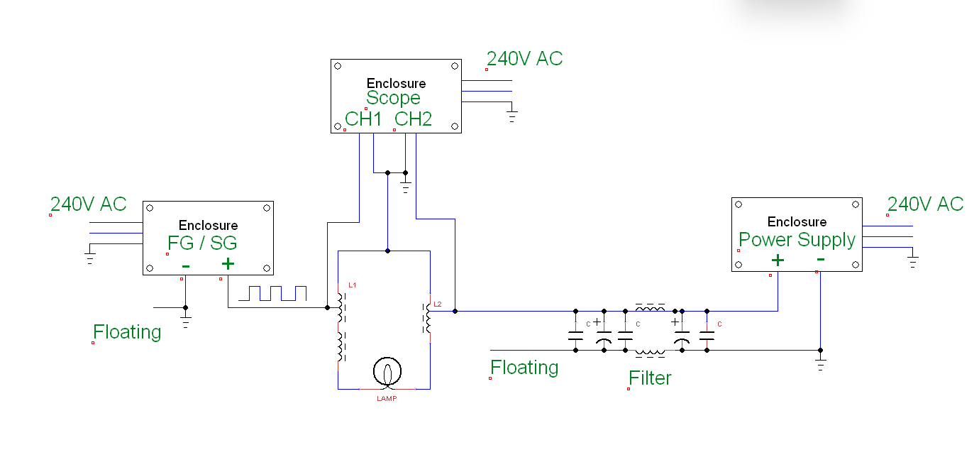
Grounding can help in some cases. But the influencing factor must be taken into account during the measurements. It only has an effect above a certain frequency.
You successfully produced the effect of input reduction. That's the most important effect of the ZPM.
This is the first time I see a ZPM still working without grounding. Yes, grounding is a great help in ZPM achieving and maintaining its resonance frequency therefore achieving the input decreasing phase.
For each ZPM device there is a certain minimal frequency (and you'll see that is depending also on the load on its output), under that minimal frequency the device will start to become less and less efficient as the frequency is lowered and going to 0. Under that minimal frequency the device is losing it's effect of decreasing the input therefore you will see the input power increasing to 1A or even above.
there are cases when the current drawn from the power supply is close to zero. There are times when grounding is necessary.
I also had situations where my ZPM's input was going close to 0, not exactly 0 but something like 0.003A. That is more easy to achieve with smaller loads (like 5W), you'll see as the loads are bigger going close to 0 on input will be harder.
With my ZPM when I put loads of 50W or 70W will be very hard to lower the input under 0.010A -0.015A.
With my ZPM the grounding (from the power grid) was always present so seeing a ZPM replica which can still work without grounding is great !
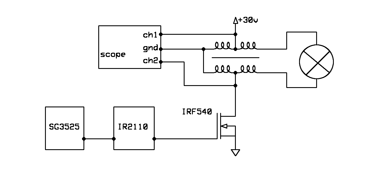
In this oscilloscope examination, I was curious as to where and how the two coils resonate. Or how I see it. Or is it visible at all.
I recognize the ZPM specific waveform pattern there. I'm always talking about ZPM waveform pattern because the waveforms produced by ZPMs are not fixed, there will be variations based on the frequency and especially on the loads. But all of them will still follow a pattern.
But as long as you have the input decrease effect that is the important thing about ZPM, the ZPM waveform pattern will be present but it is less important. The important thing is the effect.
So when this coil is at a higher voltage, it works on the other coil and charges back to the power supply.
Yes, that's what ZPM does. It "see" the DC source as a load too and it's sending power back to it. 🙂
I have not done the loading according to Fighter or YoElMiCrO. The change is not so spectacular for the load.
It would definitely be necessary to use an iron core with a larger volume and a coil with a larger surface area.
Absolutely, for bigger loads you will need a bigger Metglas core, bigger coils and also bigger wire diameter (like 0.6-0.8 mm).
Like I recommended to Itsu too, I think the best option would be an Hitachi AMCC-200:
maybe would be a good idea to get an original Hitachi Metals AMCC-200, I see it's kind of cheap now and the shipping is free:
https://ro.mouser.com/ProductDetail/Hitachi-Metals/AMCC0200?qs=0lSvoLzn4L%252BNEYf2KKv60Q%3D%3D
It's 97 Euros now, it was 135 Euros in 2015 when I bought 2 of them for 300 Euros (30 Euros shipping).
This way you can go with bigger loads. Now you know ZPM's behavior and will be easy to use the Hitachi core to achieve the input decrease effect with that core too.
As you can see, it's almost the same drawing as the one that Fighter gave us.
I'm glad my drawing (showing the coils winding directions, their magnetic polarity and how they are connected in the circuit) clarified many things.
I'm sorry I didn't draw this image before when I described the ZPM but at that moment I thought this can be easily deducted from the photos showing how the coils are connected to each other and specifying how the magnetic poles are produced by each coil. Seems that description was not enough and there remained room for confusion, that was not my intention but I had so much data and experimental results/data to organize and share...
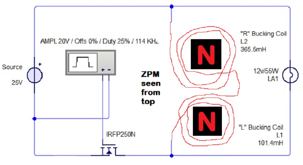
As you can see, the current can be reduced to almost zero. Probably also with higher loads. The generator effect can prevail.
This is the second successfull ZPM replication, the other one is still kept secret in Tier III in the old aboveunity site.
Both successfull replications are using equipment different than my equipment so it's great to see there is nothing specific to my equipment in order to successfully replicate ZPM.
But there are a lot of questions for me right now.
That's normal. I also have questions. Especially on how the ZPM effect can be improved by putting bigger loads on output without its resonance frequency going below the minimal frequency where ZPM becomes less and less efficient.
That's why I came public with ZPM, so people can replicate it and to find ways to improve it. But we are lucky, we have friends here in our team which are far more advanced in physics and electronics. Like YoElMiCrO, Vidura and Jagau (the order I mentioned them is random, they all are very experienced).
I'm sure in time and putting our minds together we all will have answers to these questions.
If you don't mind I would suggest to move your post to a new thread named "Atti's successful ZPM replication" so you can share your next experiments with your ZPM replica. Of course it's your decision but if you agree just let me know and I can do this for you (thread creation and moving your post and also this post).
Again, thank you for sharing it ! ☺️
Best regards,
Fighter
| "If you want to find the secrets of the universe, think in terms of
energy, frequency and
vibration." |
|
|
Nikola Tesla |