Editor's ZPM replication

  • 4.3K Views
  • Last Post 29 June 2023
editor posted this 07 November 2022

Hello All!

I was in touch with the Fighter and now I decide to show what is going on and to get some new ideas on how to get the signal that we all expect. Below is a quick video showing the simple setup. The coils are 1mm L1 cw 210T (370mH), L2 280T ( 828mH). 


The poles were tested with the phone app named Pole detector, works ok.

I have built some other coils too, with different turn numbers but the output was almost the same.

I have 2 different grounds to play with. I did use the regular power supply but my home appliances were not happy at all, so I decided to isolate everything.

For sure there are differences from Fighter setup, like the core, the position of the coils, the voltage, not sure about the ground.

the video:😁


bre


Order By: Standard | Newest | Votes
editor posted this 07 November 2022

Hello All!

I was in touch with the Fighter and now I decide to show what is going on and to get some new ideas on how to get the signal that we all expect. Below is a quick video showing the simple setup. The coils are 1mm L1 cw 210T (370mH), L2 280T ( 828mH). 


The poles were tested with the phone app named Pole detector, works ok.

I have built some other coils too, with different turn numbers but the output was almost the same.

I have 2 different grounds to play with. I did use the regular power supply but my home appliances were not happy at all, so I decided to isolate everything.

For sure there are differences from Fighter setup, like the core, the position of the coils, the voltage, not sure about the ground.

the video:😁


bre


Munny posted this 20 December 2022

We may need to use a lamp in series with rectification so the power has somewhere to go while we work out the best method for rectification.  Just take it a step at a time until we can shunt the lamp and run without ejecting the innards of the components.

We also need to setup the closed-loop framework and have that in place so when we finally get it dialed in, the system takes off on its own and we can yank the power supply cord for good.  There's a possibility an interim step will be necessary where we do double conversion.  Hopefully not, but best to plan for it during optimization.  Until we know all the factors that govern the ZPM performance, keep every option on the table.  My gut feeling is we have a situation where the ZPM sits in the middle of a transmission line and each end of the line must have the proper impedance or the ZPM simply can't do what we know it's capable of.

editor posted this 27 December 2022

Hi All!


some little progress in the last days, but i finally manage to put it together, 200-420T ration.

Just have to connect everything and wait for the xmass lights😀.


Atti posted this 06 January 2023

@editor.

Hi.

The oscilloscope is grounded, the PS is not grounded, and on the isolated transformer. I even use the inverter or just batteries. No difference...


Watch it again from 0:40.

In my opinion, one possible problem is with the mosfet gate driver.
Check again who are the members who reproduced the ZPM device and what controls they used.

I tried the following mosfet drivers.
(because if the drive of the mosfet gate is not perfect, it can get very hot. It is not certain that perfect operation is the right solution!)

-when the TL 494 output is simply controlled -IRFP260 mosfet.
- when only the output of the TL 494 controls a high-current transistor.
-SG 2535-IR2110-IRF540n
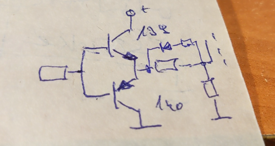
- the TL494 controls a gate driver, this is a BD 139-BD140 -IRFP260 mosfet


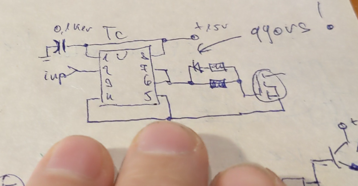
-TL494 drives a dedicated driver TC4429 -IRFP260 mosfet

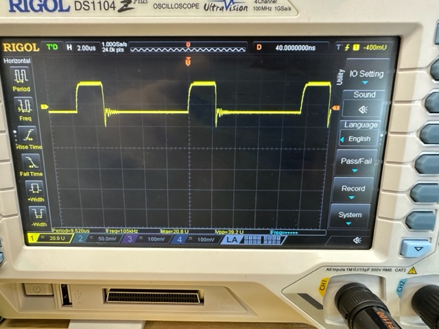
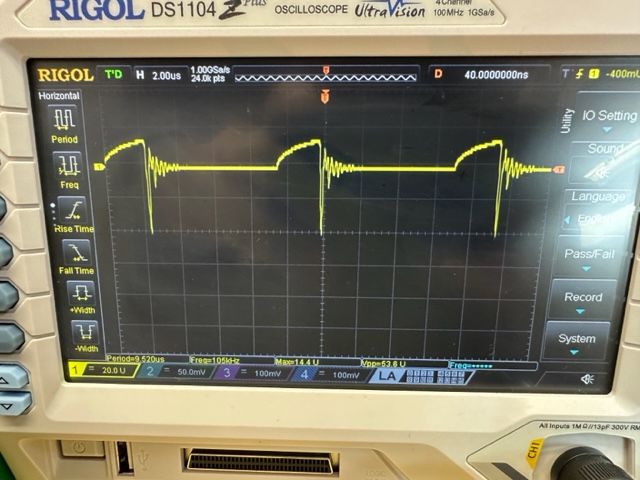
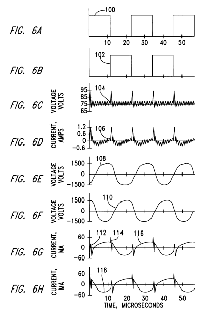
The transistor is slow. Therefore, there is no proper spike.
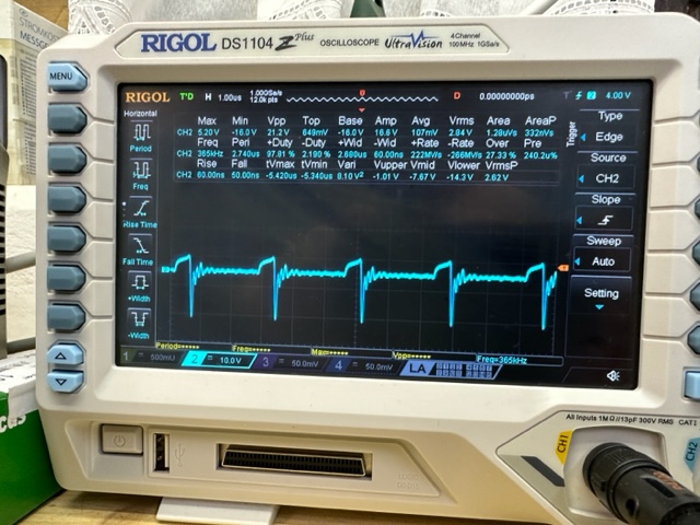
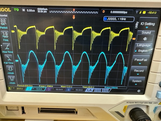
The speed of the gate drives has a big influence. It does not allow swings. Furthermore, there is no external excitation. You can see it here:


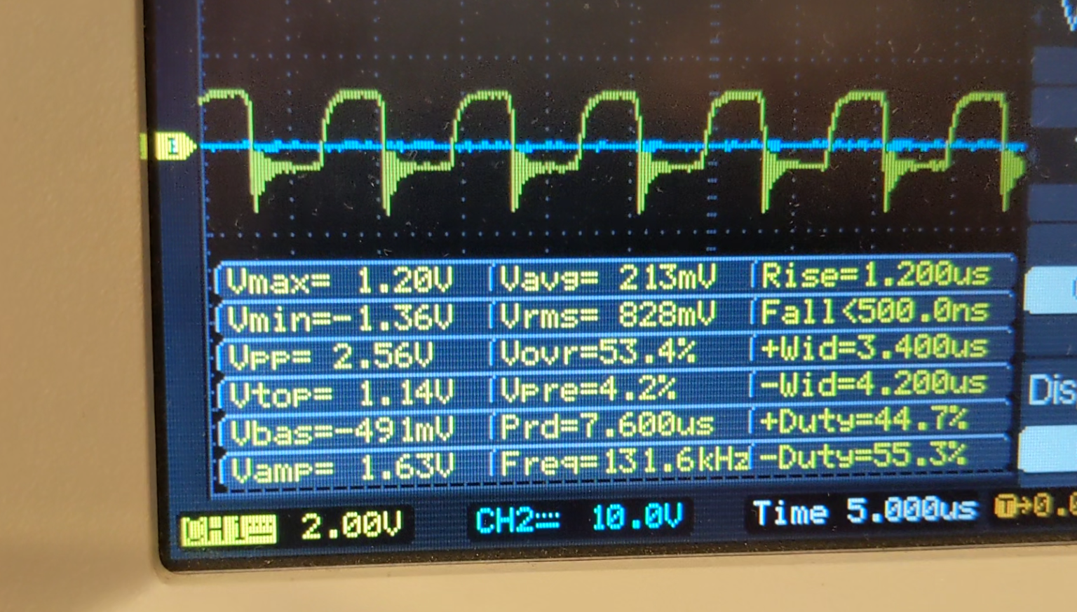
The mosfet does not heat up at all!

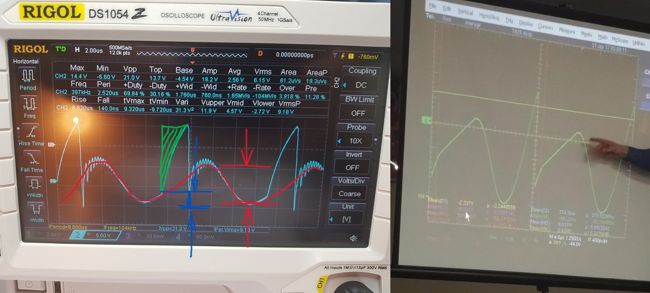
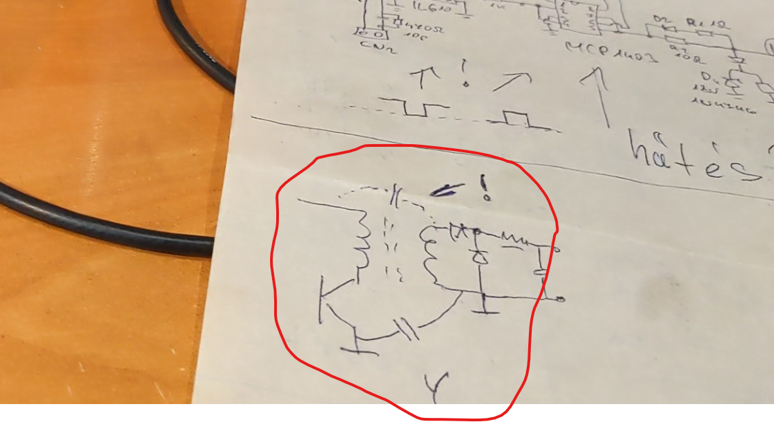
So I conclude that driving the mosfet gate requires a swing time. If this is present and combined with the parasitic capacitance, resonance can occur. The presence of the negative spike (positive current) also heats the mosfet.

-Furthermore, it is questionable why Fighter's mosfe got so hot. Why does it have to be cooled to such an extent?
This could be a sign of operation.

And one more thing. Don't forget the importance of parasitic capacitances either.


Atti.

editor posted this 16 December 2022

Hi all, 


Nothing special to share, but just to let you know that I'm still in the loop.

Finish printing all the parts with PETG and start to wind the first coil. Hope to finish the

coils this weekend.


Have a nice day or night, e


Fighter posted this 18 December 2022

Quoting:editor

We don't need formulas at all, just a selfrunning machine, that's it. It is still not presented, but we are aiming for that goal, I hope. Then we can calculate and argue as much as we want. This is just my humble opinion.The only USEFULL COP device for me is selfrunning, and that's it.

I agree, that is the ideal scenario where this kind of calculations will simply not be necessay anymore. But that's still a goal, last time when I tried to rectify ZPM's output it destroyed the capacitor on one of my custom made bridge-rectifier channels:

This is the basic schema which was modified/adapted for the different layout shown in the image above:

Seems the MBR4045PT high-frequency Schottky diodes were not able to handle the high-frequency and high-voltage negative pulses (sometimes going up to 180-220V) on ZPM's output and these pulses reached the electrolytic capacitor. It did get very hot within about half of minute and its top got deformed. So it was gone, I'm not sure if all the diodes are still functional, didn't verified them since then.

So yes, there is still a lot of work to do on ZPM's output rectification. Probably I'll need to rebuild this bridge-rectifier using much faster components with much higher voltage.

Regards,

Fighter

"If you want to find the secrets of the universe, think in terms of energy, frequency and vibration."
Nikola Tesla
Atti posted this 31 December 2022

Hi everyone.

@editor.
Notice the difference between the two pictures. In your case, 5w-50w.
Let's look at Fighter's picture.


You can see the negative spike.
- Blue marked area.
It depends on the rate of current change and the size of the load.
- Green marked area.
The greater the magnitude of the load, the larger this area.
(Rounds the edge of the square sign.)
-Red marked area.
That's what's interesting about it all. In my opinion, the magnitude of this depends on the parasitic capacitance.
If it is capacity, then it is resonance.
Let's look at J.L.Naudin's diagram, or the patent diagram.
If the driving pulse is a square, then how will the voltage on the secondary side be sinusoidal?

If I place a neon lamp at the connection point of the two coils, it will light up according to the parameters. It gets stronger as the frequency increases. Since the circle wants to close somewhere, it chooses the shortest path. And this is grounding.

However, it doesn't matter where I put it!

  Sometimes the power taken from the network increases and sometimes it decreases. Frequency, duty factor and supply voltage dependent.

I did a quick scan.
Full reproduction will not be easy.
Wire the coils based on the parameters already specified.
So 150 and 300 threads.
(actually, 2X150 and 60 threads on each column due to a later test)
I was just testing in this setting, currently the current is not close to zero.
I'm just setting the frequency here. The filling is 20-25%.
You can see the several resonant members in the breaks.


Equally...


Atti.

editor posted this 05 January 2023

Hi Cd_sharp

The oscilloscope is grounded, the PS is not grounded, and on the isolated transformer. I even use the inverter or just batteries. No difference...

Even if I change the grounding, the negati of the PS is grounded, but the oscilloscope is not grounded. 


this is the closest that i got yesterday.


br, e

Atti posted this 09 November 2022

The grounding connection is not something separate like a wire I added.

It's the grounding of the DC source going through the 3rd wire in DC source's power cord and then to the clamps in the power socket to the grounding of the electrical grid:


Hi everyone.

Just a few pictures of a quick job.
I have checked several times, there is no short circuit anywhere. No physical contact with anything. The coils are separate and not connected. So there is no stimulation either. There is only capacitive path closure. This is a simple disassembled microwave oven transformer.

About my power supply:
-Self-made, repeatedly tested and accurate. The power supply has a toroidal transformer. So it has no grounding.
-My other power supply also has a toroidal transformer (but it is switching mode, so it is not linear) while it also does not have grounding.
-The H bridge is a combination of SG3525 and IR2110. It also does not have mains grounding.

Nevertheless, the grounding of the oscilloscope (or the use of a separate grounding) is capacitively closed to the power supply. A Led indicator shows the low voltage. This weak voltage can be added to the excitation voltage at a suitable frequency. Or it can completely mess up the measurement. The voltage is not weak in all cases. Look at the analog multimeter.
- The H bridge does not produce enough disturbance to provide excitation when connected to the ground.
- For me, the most interesting thing is that this is the same situation with batteries. I also tried it with the battery of an 18V cordless drill.
-The frequency is some max 50KHz.

Interesting.

Atti.

editor posted this 30 November 2022

Hi All!

Just some update, from the last time. I have to move again to my first lab, the temperatures are below zero so it is hard to experiment in those conditions.
I got some inverters and built an isolated transformer from 2 transformers from an old broken UPS. Works well for powering the scope, I also add a ground switch so I have all the options available. Still have to experiment a bit with different PS the best result was with the one minus connected to ground.
Today I played it with a ZPE with different loads but not getting the low power consumption like expected. The waveform is from the coils; the bulb is 50W low brightness and 1.7A 25V from accu. 


Have a great day or night, e

editor posted this 21 December 2022

Hi Munny!


I agree with the impedance comment. Well see. Got a few kg of copper today from a friend, so I will try to continue as soon as possible. Just have to print another part for the former, because I was too strong... Then the goal is to get the effect, find the resonance like in one of the Fighter's video.


br, e

Close