
I transferred my thread on Ferrite at Work here to BeyondUnity.org
Ferrite at Work
- 1.8K Views
- Last Post 18 December 2023
Jagau
posted this
16 December 2023
I transferred my thread on Ferrite at Work here to BeyondUnity.org
- Liked by
-
-


Fighter
posted this
18 December 2023
Hello,
As I promised to Jagau the import of this thread is now complete.
It has 141 posts and for each it needed direct access to our database, image importing, links, text formatting and a lot of attention to details. Plus a lot of translations from Russian to English where Google Translate was very imprecise sometimes... 🙂
As this process cannot be automated, it can be done only manually and it's very time consuming.
But it's worth the effort, in time we gonna get all our data here to home where it belongs because it's the work and the property of the members of our team.
Jagau requested here for his threads to be removed from the old aboveunity site but of course that cuckoo-boy from the old site can't do that because without the work done and shared there by our team he would have nothing on his site. 😉
As the device shared in this thread is overunity it's now officially tagged with the "Beyond-Unity" tag and I will add it to the section "Our Beyond-Unity Devices" on the right-side of our site.
Jagau, if you find any (possible) errors I've made during the import please feel free to edit/correct them.
The thread is officially yours now.
Regards,
Fighter
| "If you want to find the secrets of the universe, think in terms of energy, frequency and vibration." | ||
| Nikola Tesla | ||
- Liked by
-

-

-
-
Jagau
posted this
18 December 2023
WOW what a great job Fighter, it's like a Christmas present, thank you a thousand times.
Researchers can also follow this thread and its evolution
on the site here of BeyondUnity.org
Jagau
- Liked by
-
-
-
-
Fighter
posted this
18 December 2023
You're welcome ! 🙂
This is your research and belongs to our home where you are and where our entire team is.
Fighter
| "If you want to find the secrets of the universe, think in terms of energy, frequency and vibration." | ||
| Nikola Tesla | ||
- Liked by
-
-
-
-

UndisclosedMember
posted this
22 September 2020
@thaelin,
here is the value of the potentiometer of my 2 devices:
44.2K for the one with the Litz wire and 40.4K for the one with the tinned copper wire. With this setting, the LEDs are very bright and do not flash.
Check the correct order of your connections, because this assembly does not present any difficulty, it must light up as soon as the power is turned on, either in flashing or fixed mode. The potentiometer must be adjusted at the limit of the flashing / fixed LEDs. Remember to reverse the two ends of L3 from the diagram in the first post above. Check the data sheet of your transistor, its base is not always the middle leg. Obviously, scrupulously respect the winding directions of the coils, including L6 placed in 8.
For all, according to my findings:
1 / By adjusting the potentiometer so that the 2 LEDs flash quickly, you obtain a complete self-charge of the batteries, within a time which depends on the initial voltage, but at most in a few hours. The voltage then slightly exceeds 2.4 volts. When the LEDs are on steadily, the complete self-charging of the batteries also operates, within a slightly longer time and the maximum voltage is slightly lower, but still higher than 2.3 Volts.
2 / I brought the two tori together and positioned them in all possible arrangements. I did not see any improvement in the brightness of the LEDs or in the evolution of the voltage.
3 / On my device with the Litz wire, the D1 led is slightly brighter on D2. On the other device, D1 and D2 have approximately the same brightness. The advantage with Litz's thread is very moderate: D1 a little brighter, but D2 a little less than on the other device.
4 / By placing a capacitor of very small value in parallel with D1 or D2 (test with a panel of capacitors to find the right value), we obtain a very significant increase in the brightness of D1, but the voltage of the battery drops .
5 / By placing a neodymium magnet between L4 and l5, North against the outer edge of the torus, and with an adjustment of the potentiometer, I succeeded in lighting 4 leds connected in parallel, very bright. The voltage has dropped to around 1.6V. I did not continue the experiment beyond a few minutes. I removed the magnet and set to classic mode. This morning, the battery had fully recovered and was around 2.4 Volts.
Greetings
Mimo
- Liked by
-
-
-
UndisclosedMember
posted this
23 September 2020
Jagau first of all thank you for the circuit, it is really interesting! Secondly I am just a simple experimenter, at the lowest level than the other guys in here, but thanks for your encouraging words
Indeed as I see it Nanoperm cores gives faster charging!! I got this little Li-po battery from 3.40v to 3.94v in few minutes and raising as we speak!! I know the battery has low capacity so faster charging is normal, but I will check Li-ion as well to be sure.
I ll try some more variations I have in my mind .. I will keep you updated guys.
- Liked by
-
-
-
Jagau
posted this
12 September 2020
An easy to assemble circuit that works, I have tried it myself and it is stable and functional.
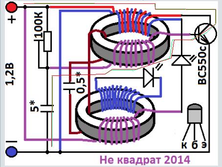
This circuit is not from me it is from a Russian researcher who introduces himself under the nick name of "not a square" in russian 'Не квадрат'' 'on this website you can talk to him.
https://strannik-2.ru/index.php/forum/prakticheskaya-elektronika/220-u-menya-interesnaya-skhema?start=1485
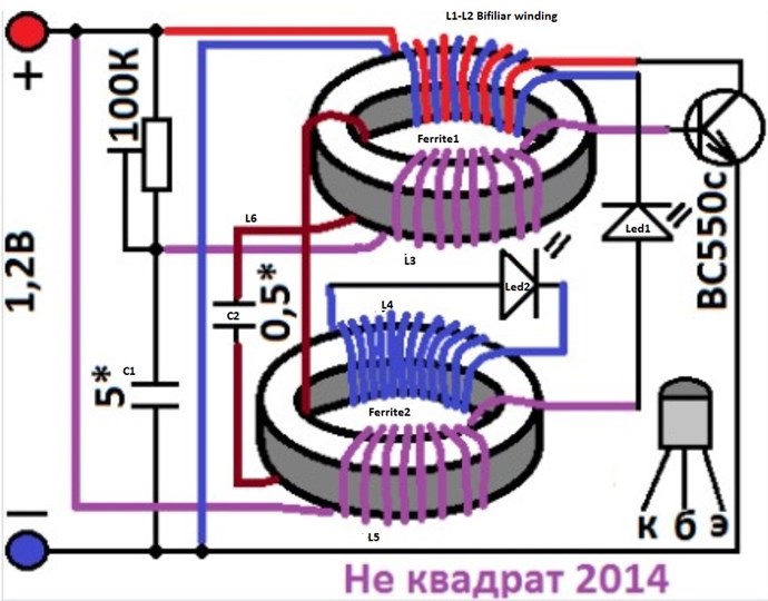
The circuit has been working for 5 days now and the voltage is very stable. Here is the circuit:
I admit that I am happy with the result and that the ferrite fuel is doing its job. This circuit deserves to be studied and developed.
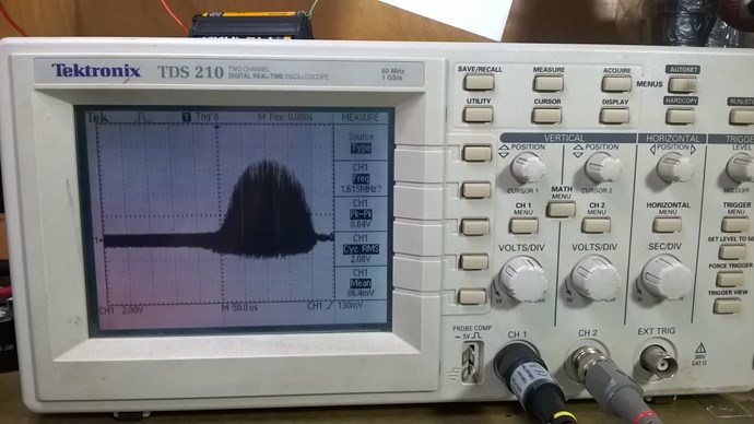
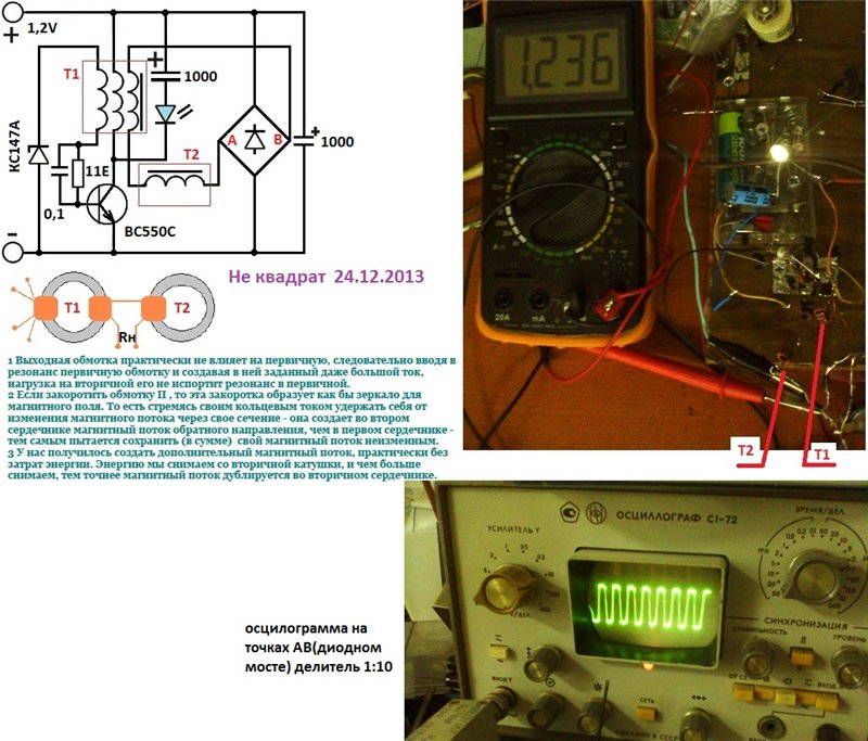
A view of the oscilloscope on the collector:
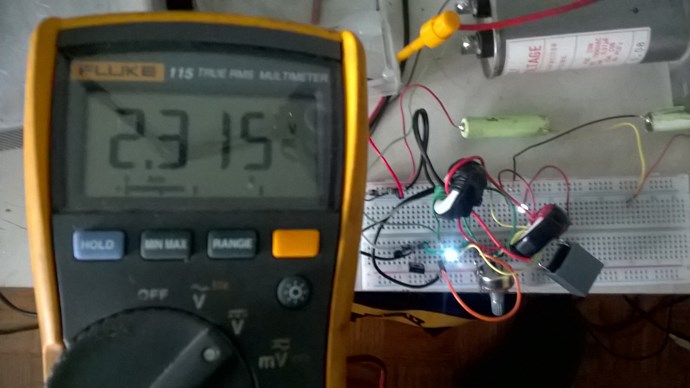
I started at 2.3 volts and now after 5 days the circuit is stabilized at 2.457 volts
Jagau
- Liked by
-
-

Jagau
posted this
13 September 2020
Good morning all
I did in schematic with Spice while respecting the wire colors and the start and end of the wires on each of the 2 ferrites.
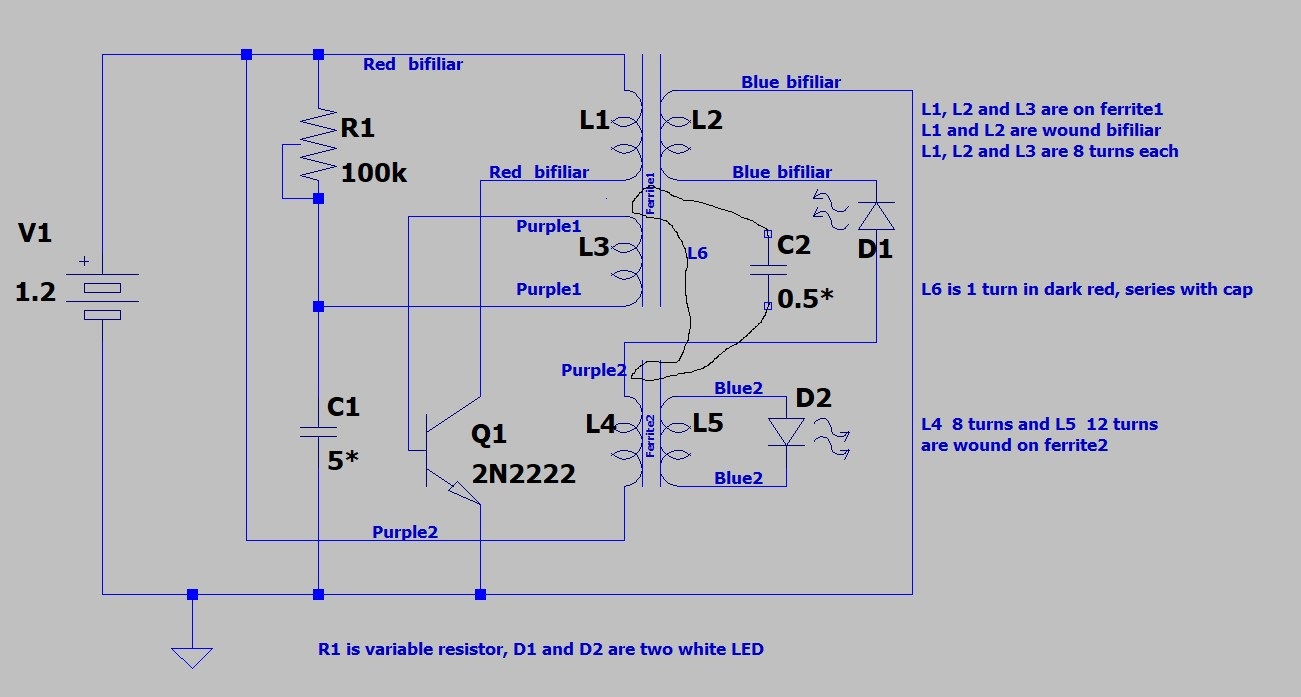
A spice reproduction of the author's original drawing.
As I said in a previous post, I modified the circuit a little so that the battery charge increases more quickly. From the first day until today (fifth day) the load has stabilized more than it was at the beginning while still operating the circuit and with the two LEDs on.
Modification I made from original circuit.
I took off the cap. 0.5 uf and connect the loop of 1 single turn without the cap. Adjusted the capacitor from 5uf to 1.8uf which gave me a very quick increase in circuit performance.
I made a second circuit with a TV ferrite that works great too.
Am experimenting with this circuit without any battery, only with preloaded caps and the preliminary results are very good
hope this help
Jagau
- Liked by
-
-
UndisclosedMember
posted this
14 September 2020
Nekvadrat (user name added by Fighter):
с этого начиналось:
...подключил к подсевшему аккумулятору (1,18В)...напряжение поднялось до 1,236 - держится несколько часов
Translation (added by Fighter):
this is how it started:
...connected it to a dead battery (1.18V)... the voltage rose to 1.236 - lasts for several hours
- Liked by
-
-

Jagau
posted this
14 September 2020
Hi all
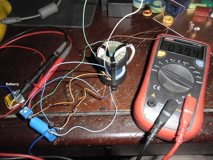
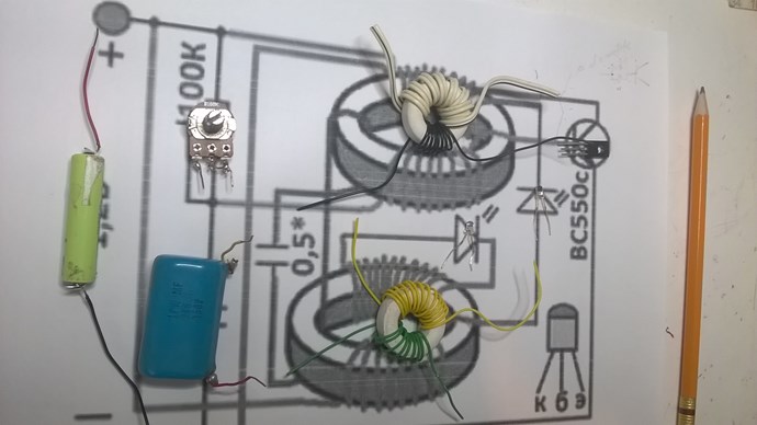
A picture is worth a thousand words
The direction of the windings is very important
I took a photo, take a good look at the start and end of each coil.
As you can see the first coil at the top,the white one is a bifiliary winding (2 wires)
Above and below very important, adjust the pot of 100k until an increase in the voltage of the battery.
At the beginning the leds are flashing it's good you have let the system stabilize and you are there.
Jagau
- Liked by
-
-

Our Beyond-Unity Devices
Members Currently Online:
No one online at the moment
Categories
Hot Topics
