Fighter's ZPM (Zero Point Module) failed replication by Itsu

  • 8.1K Views
  • Last Post 18 December 2022
Itsu posted this 07 November 2022

Hello all,

i opened this thread to discuss my replication of Fighter's ZPE (Zero Point Module).

I already opened a similar thread on OUR.com (https://www.overunityresearch.com/index.php?topic=4374.msg101654#msg101654 ), but will transfer some data from there to here.

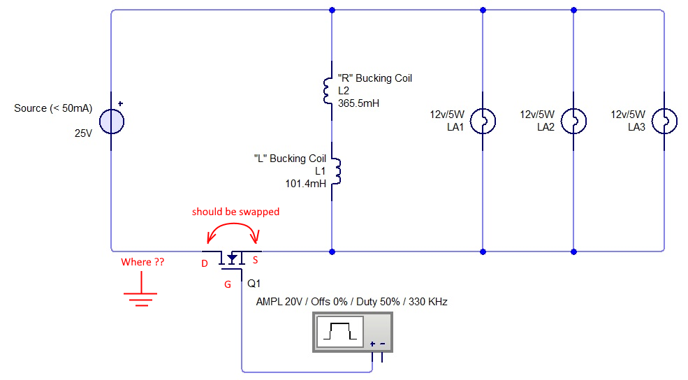
Initially i understood that the below diagram was correct and complete, but it turns out its not.
There is a ground connection somewhere, but i am not sure where it is exactly, hopefully someone can tell me.
The MOSFET is shown wrong as the Drain and Source should be swapped, which was corrected later in Fighter his thread so therefor the mentioning in red.

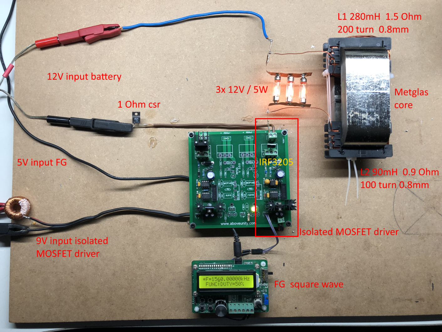
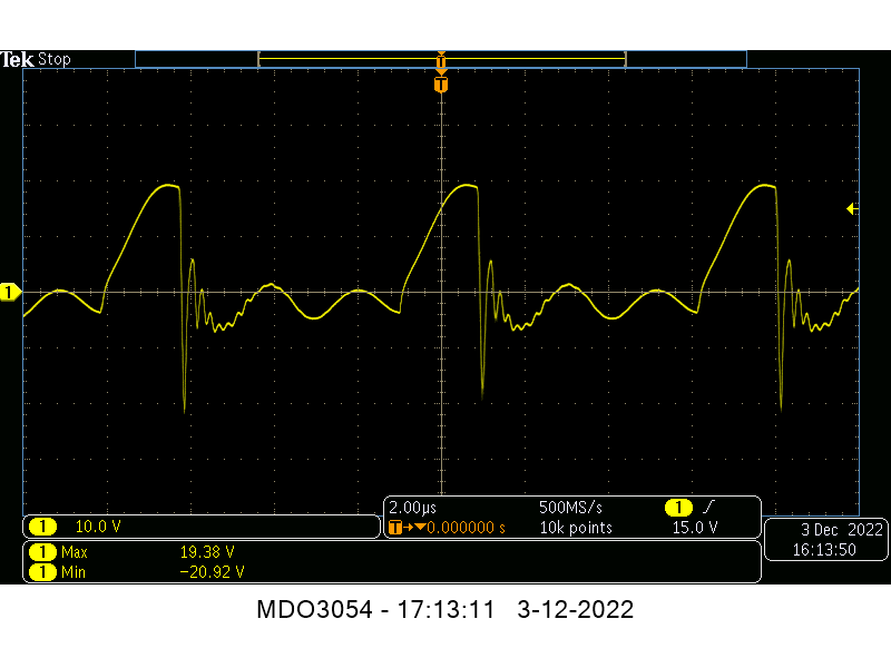
I have build up a similar circuit and the data is shown here: 
(Be aware that the induction measurement was done at 10kHz, but due to the influence of the metglas core it can be (and is) completly different on other frequencies, see my thread on OUR.com for a VNA scan of the coil/core)


I am using a 12V battery for now as my PS (minus NOT grounded) was acting weird due to all the pulses coming back from the ZPE device.
Up till now no special effects or resonance in a 0 to 5MHz range are seen with this setup, but as said the grounding may be the problem here.

Itsu
Itsu posted this 05 December 2022

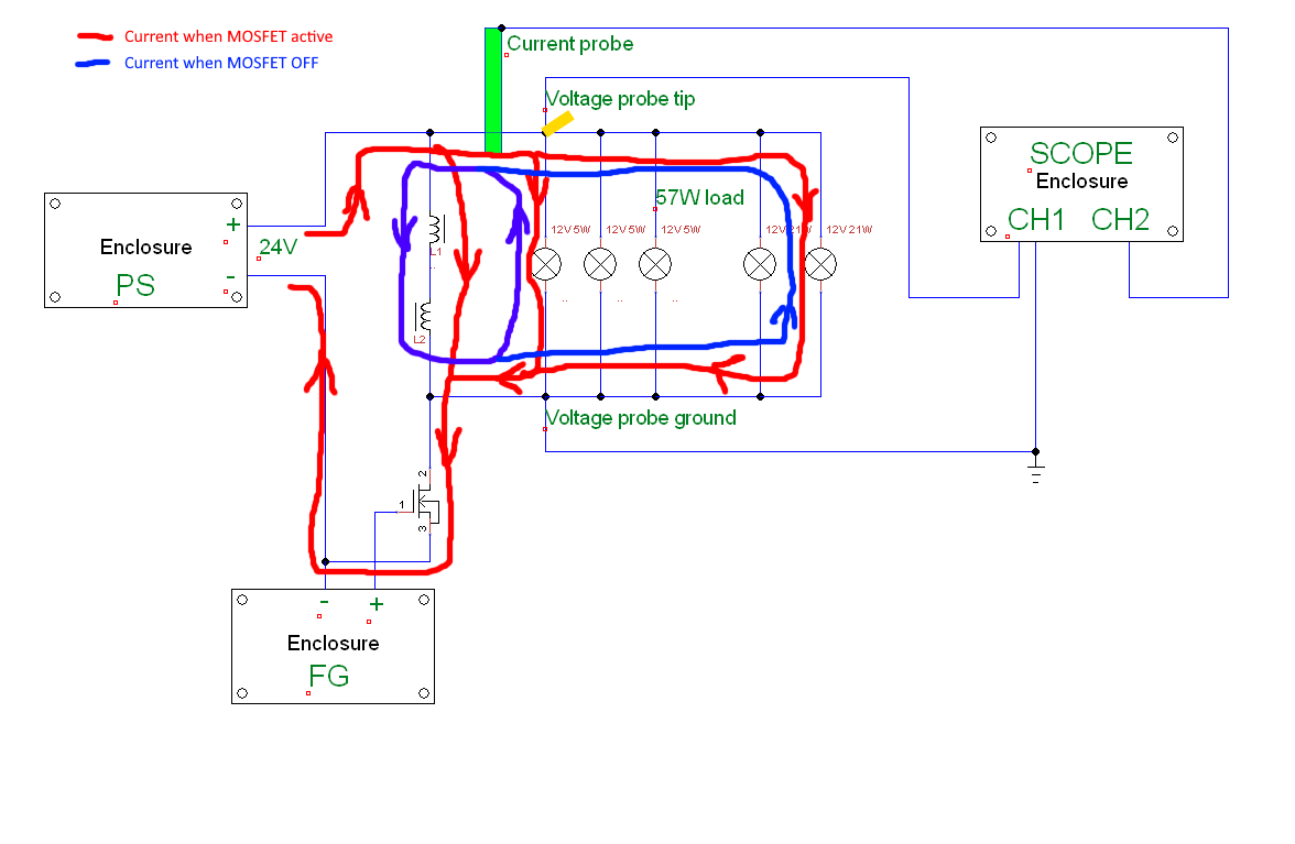
I have removed the ground from the Power Supply (so the DUT is floating as is the FG) to be able to measure the voltage across the load / bulbs (57W).

I also measure the current through the load / bulbs using my current probe see diagram:


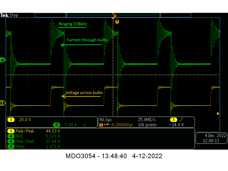
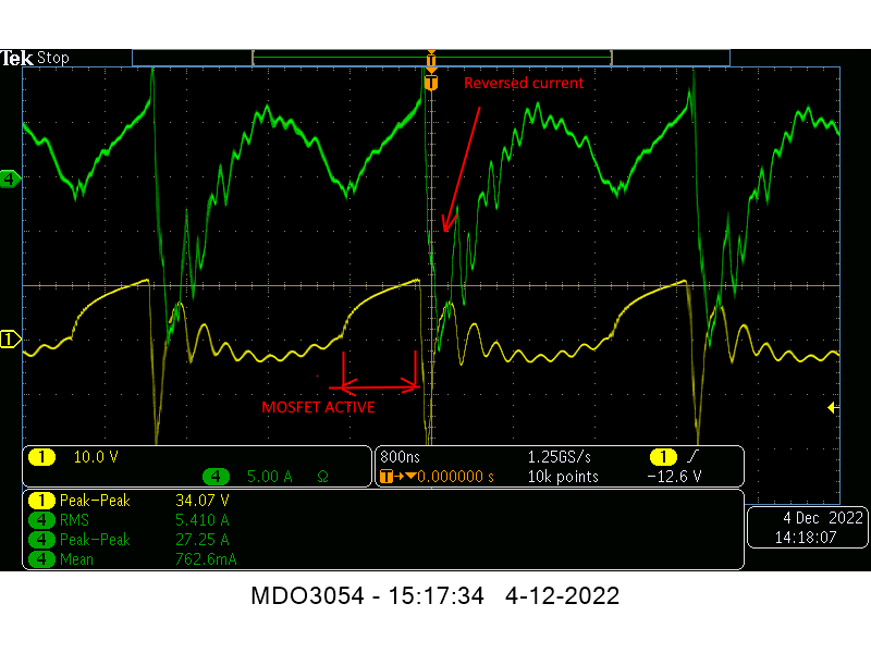
First screenshot is at 10kHz @ 25% Duty Cycle, for info see screenshot text:

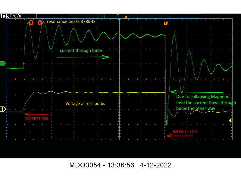
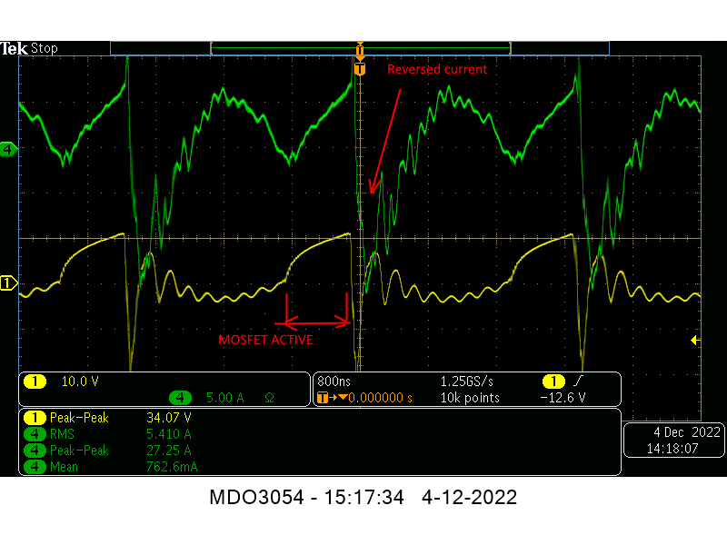
Second screenshot is zoomed in of the first screenshot with text:

What we see is the voltage across the bulbs increase as is the current through the bulbs.

At the same time the magnetic field in the coils is build up parallel.

We see strong ringing on the current signal pointing to a resonance point around 378kHz (due to the PS).

When the MOSFET goes off, the voltage drops as is the current, but reverses as now the BEMF created from the collapsing magnetic field of the coils tries to maintain the current flowing in the same direction and thus, start flowing through the bulbs the other way (the negative current peak), see also the diagram. 


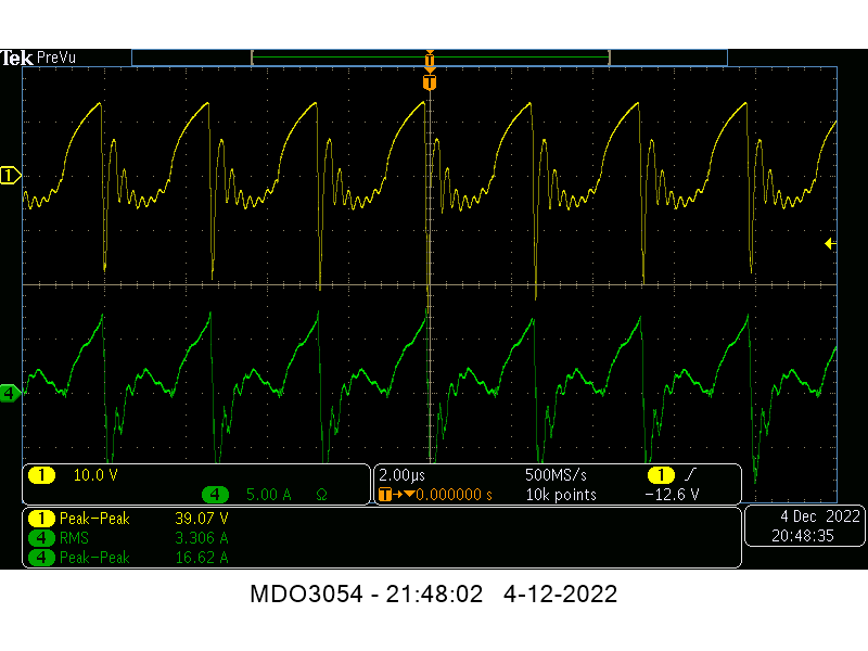
Third screenshot is taken at the noted 378kHz resonance frequency:

You can see that the heavy resonance disturbs the signals (by the way, no resonance when using the battery, so this comes from adding the PS into the mix), but the basic flow of current through the bulbs is the same as at 10kHz.

This is my interpretation of what i see happening, any comments / corrections are appreciated.


Regards Itsu

Vidura posted this 05 December 2022

Itsu, thanks for the testing.I think that it is pretty the same as in my tests, if the current flow is as drawings in the picture, it is DC in the inductor. Maybe this is the issue, when the resonance is achieved in the core(magnetic) the current should have a reversal in the inductor, depending on the phase relationship, the power factor could become negative, and power would be fed back to the supply. In this scope shot( I don't know which setup was used) https://www.beyondunity.org/content/uploads/b18b74e6-1d88-4bab-aea2-af43000ae293/2c7d208b-d53f-4962-b7d5-af610026380dno-saturation-voltage.png

A sinusoidal pattern is visible, you could try to adjust the puls duration to a quarter or half period and then vary the frequency until matching resonance (if your FG is adjustable separately)

Vidura

Itsu posted this 05 December 2022

Hi Vidura,

you mean this screenshot:

taken form this post:

https://www.beyondunity.org/thread/fighter-s-zpm-zero-point-module-replication-by-itsu/?p=11&order=all#comment-70a0dd96-0983-4acd-8474-af6100266d22

Its the same setup as in my last post (voltage across the bulbs (57W) at 24V input 25% Duty Cycle.

When adjusting the pulse duration (Duty Cycle) to see a half period (32%) and then vary the frequency untill matching resonance (278kHz) i get this screenshot:


Yellow is voltage across the bulbs, green the current through the bulbs.

But no effect (dip in input current) seen.


thanks,   Itsu

editor posted this 05 December 2022

Quoting:Itsu


Hi Itsu, i can comment just this, it looks like I have the some waveform like you in some cases.

Thansk for sharing. 

regards, e


Fighter posted this 06 December 2022

Hi Itsu,

Using one of the images from your scope with your annotations:

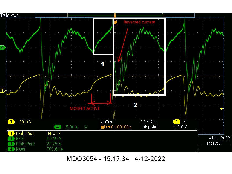
The only consumed input is the one of 25% ("MOSFET active"), the other variations of the magnetic field are free (without any energy consumed from the input) and those variations are powering your light bulbs.

So 75% of the time the light bulbs are powered without input, it really doesn't matter if the magnetic field is collapsing or raising and collapsing multiple times (the "ringing"), it's still variating magnetic field producing real energy.

That energy is not only powering up the light bulbs but also sent back to the DC source, why isn't the DC source see that "help" ? It should show the input decreasing effect.

In other image I see current peak-to-peak 16.62 A and that's a lot of magnetic field variation.

Anyhow, the conclusion is there are free magnetic field variations 75% of the time producing real energy and powering up the light bulbs.

Just my interpretation of what I see. So your ZPM is actually working fine, you have the specific ZPM waveform pattern (the voltage), the only question remaining is why the DC source doesn't see the "help" received from ZPM and keeps insisting the input is 3A even if that is consumed in just 25% of the time.

So 75% of the time the lightbulbs are not consuming power from the DC source and it should see that.

What's the difference between our DC sources that make mine to see that "help" and yours doesn't see it ? Atti's DC source also see that "help" in his successful replication.

I mean it's very clear that these 3A are not permanent consumption.

Regards,

Fighter

"If you want to find the secrets of the universe, think in terms of energy, frequency and vibration."
Nikola Tesla
Itsu posted this 06 December 2022

Fighter,

thanks for your insights.

But i do not agree that 75% of the time the light bulbs are powered without input.

Look at the green current trace over 1 cycle, i think there is about 66% above the current zero line, so about 2/3.
Thats the current going through the bulbs coming from the PS.

Then we have the 1/3 negative current, thats from the collapsing magnetic field from the coils which was also supplied by the PS in the first place, so all power we see basically comes from the PS.

The RMS value states 5.4A which is about right for powering 57W of bulbs brightly.


There are pulses going back into the PS, but it depends on the design of the PS if it is registrated on the Volt- / Amp meters.
My present simple 24V volt PS has no meters, so i am using DMM's to measure them and the only thing i see is that the Voltmeter DMM is increasing to 31V due to influence of the (resonance?) pulses back into the PS, the Amp DDM does stay about the correct value, but again, DMM's and PS meters are no good for frequencies above 10 or 20kHz, they start deviate greatly both positive and negative so should not be used.

Regards Itsu

Fighter posted this 07 December 2022

Hi Itsu,

Look at the green current trace over 1 cycle, i think there is about 66% above the current zero line, so about 2/3.
Thats the current going through the bulbs coming from the PS.

The entire energy coming from the input when the MOSFET is on is producing that deep negative current you see when the magnetic field is collapsing. The rest of 75% are just free magnetic field oscillations. That means extra-energy.

Also, you see there collapsing magnetic field is producing a peak-to-peak 27.5A current, right ?

Do you really think your DC source is providing 13.75A (half of peak-to-peak) in that small region #1 below to produce that magnetic field before it's collapsing ?...

Compare the height of the current raising while the MOSFET is on (25%) with the negative height shown while the magnetic field is collapsing.

Your RMS 5.410A is also including the current produced in the 75% of the time while the MOSFET is off ! šŸ™‚

Let's put this visually:

Compare the current consumed in region #1 while the MOSFET is on with the current produced while the MOSFET is off in region #2. See the amplitude of the current therefore magnetic field multiple oscilations (positive or negative, it really doesn't matter, they're still producing energy) produced in region #2 while the Metglas core is "ringing" free without any help from input. I mean the quantity of energy consumed in region #1 is obviously a few times smaller than the energy produced in region #2. Remember any of those magnetic field oscillations, doesn't matter if negative or positive, is producing energy while the MOSFET is off. We literally can see here to COP of the device ! šŸ™‚

The same about voltage, the only consumed voltage is in region #1, what's in region #2 is generated free when the core is "ringing" while the MOSFET is off.

Anyway, seems you have a very different interpretation, I'm not here to convince you even if for me is crystal-clear what I see.

Regards,

Fighter

"If you want to find the secrets of the universe, think in terms of energy, frequency and vibration."
Nikola Tesla
  • Liked by
  • Inception
  • YoElMiCrO
Munny posted this 07 December 2022

Quoting:Itsu

There are pulses going back into the PS, but it depends on the design of the PS if it is registrated on the Volt- / Amp meters.
My present simple 24V volt PS has no meters, so i am using DMM's to measure them and the only thing i see is that the Voltmeter DMM is increasing to 31V due to influence of the (resonance?) pulses back into the PS, the Amp DDM does stay about the correct value, but again, DMM's and PS meters are no good for frequencies above 10 or 20kHz, they start deviate greatly both positive and negative so should not be used.

Itsu,

Do you have a method to measure the power draw of the power supply at the wall socket?

If you can get a solid reading there, next try a static DC load to match the same reading you get while powering the device.  That will tell you the efficiency of the power supply and give you a pretty comfortable feeling of the actual wattage the power supply is delivering to your device on the input side.

If it's a switching power supply as I suspect it is, the rectification diodes may put a significant amount of noise on the line.  If that's the case, see if you have an old linear power supply you can use and step through the same process.  With a linear power supply and good current carrying wires to the wall socket, the waveforms should be quite clean since the line power is a low resistance current source.

Hope this helps.  I used this method in the past when trying to figure out the goal wattage needed for the old Ruslan device NickZ has been working on for years now.  It can be a bit of moving target, but the steps are always the same, so you just iterate until you are in the area of interest.  You can be pretty confident what the actual power demand is or has to be.

Itsu posted this 07 December 2022

Fighter,

thanks for your insights again, but i still do not agree with it.

You compare region 1 with region 2, but you cannot do that IMO.
Region 1 (MOSFET active) should be compared with only a small fraction (left side) of your region 2, the rest is reactive power coming from the resonance which is sloshing power back and forth between inductance (coils) and capacitance (very probably from inside the PS as i do not have this resonance when using batteries).

This reactive power looks impressive but is no real power.

Anyway, i do agree with you when saying that we seem to have a very different interpretation šŸ˜€


Itsu

Itsu posted this 07 December 2022

Hi Munny,

thanks for your suggestion, i did suggest the same to Fighter some time ago and it seems he did, but the results were not conclusive he mentioned.

Anyway, i can do that test later today, but i have no reasons yet to doubt my results seen on my bench where no abnormalities are seen / measured.

Up till now all the PS's / batteries i used are delivering all the power needed to light up the bulbs, and this test probably would confirm that, but   

for completeness i will give it a try.

Regards Itsu

Close