Fighter's ZPM (Zero Point Module) failed replication by Itsu

  • 8.1K Views
  • Last Post 18 December 2022
Itsu posted this 07 November 2022

Hello all,

i opened this thread to discuss my replication of Fighter's ZPE (Zero Point Module).

I already opened a similar thread on OUR.com (https://www.overunityresearch.com/index.php?topic=4374.msg101654#msg101654 ), but will transfer some data from there to here.

Initially i understood that the below diagram was correct and complete, but it turns out its not.
There is a ground connection somewhere, but i am not sure where it is exactly, hopefully someone can tell me.
The MOSFET is shown wrong as the Drain and Source should be swapped, which was corrected later in Fighter his thread so therefor the mentioning in red.

I have build up a similar circuit and the data is shown here: 
(Be aware that the induction measurement was done at 10kHz, but due to the influence of the metglas core it can be (and is) completly different on other frequencies, see my thread on OUR.com for a VNA scan of the coil/core)


I am using a 12V battery for now as my PS (minus NOT grounded) was acting weird due to all the pulses coming back from the ZPE device.
Up till now no special effects or resonance in a 0 to 5MHz range are seen with this setup, but as said the grounding may be the problem here.

Itsu

Itsu posted this 12 December 2022

Quoting:Shelfordella

It looks good if V x I are instantaneous products, or V(t) x I(t), which is the same as Pavg=Vrms x Irms x pf. I guess yellow is the power supply voltage instead of the voltage pulse towards the inductor.

Shelfordella,

V x I ARE instantaneous products.

As i mentioned earlier, the scope math function does NOT use rms, avr (mean) or p2p values, it uses the instantaneous values of the traces (at a miljoen points on the screen or so) and takes the average (mean) of those products arriving at the 717mW.

Yes, yellow is the power supply voltage at the PS (input to the device), as that is what we want, the input power into the device, not somewhere inbetween.

Thanks,  Itsu

  • Liked by
  • Inception
  • Vidura
Itsu posted this 12 December 2022

Quoting:bigmotherwhale

Unfortunately Itsu all that scope shot shows is a rediculously slow charging of an inductor and a normal tranformer action, and looking at your setup its plainly obvious why, the 1 ohm resistor in the supply being a blatantly obvious reason for one.  

We are not looking for LC ressonance, of course that will give you lower amp draw, energy is being returned to the supply. 

You need to go back to the basics, no ammount of coil winding will help, I can get a sawtooth wave using an off the shelf common mode choke. With a pretty dire switching arangement. 

You are attempting to measure something you havent even got by the looks of it. 

you have a good switch board, see how much current you can get through a normal resistor in what rise time, your slope should be in the nanoseconds, once you have that move on to driving an inductor, you may need to use a snubber network for a clean pulse.  

You want your pulse into the core to kick like a mule, there is no need to get any kind of saturation, not like you could saturate one of these cores in a million years with a setup like this.

Reduce the input duty cycle to a few % the freqency doesnt matter at this stage, only duty cycle, start low 1 - 10khz 

I hope this helps, as it seems your trying so hard with these expensive toys, you have missed the key points. 

BMW,

Thanks for your input.

You seem to react on both my Jagau replication and my general ZPM replication, allow me to split them here for now.

First the Jagau replication.

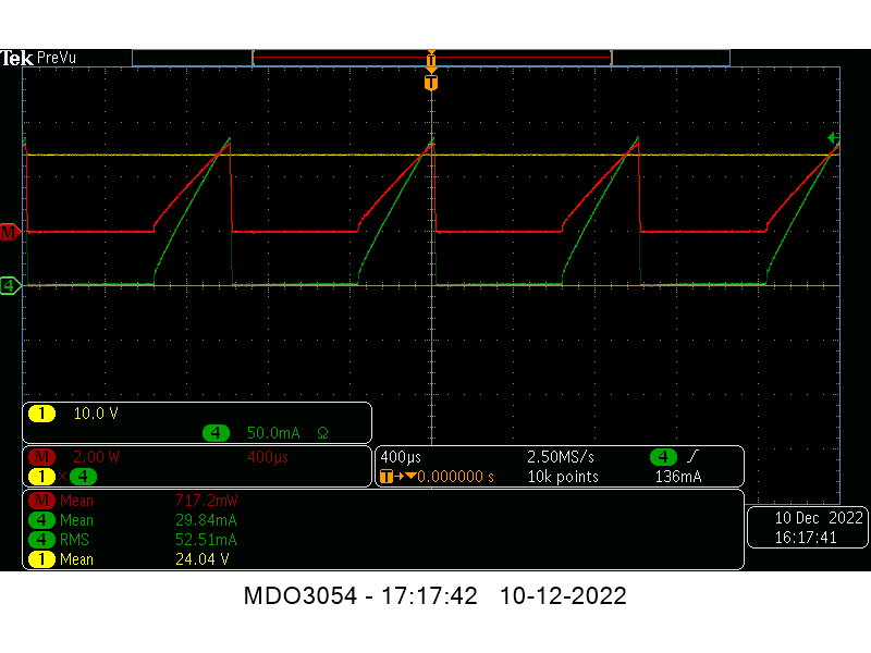
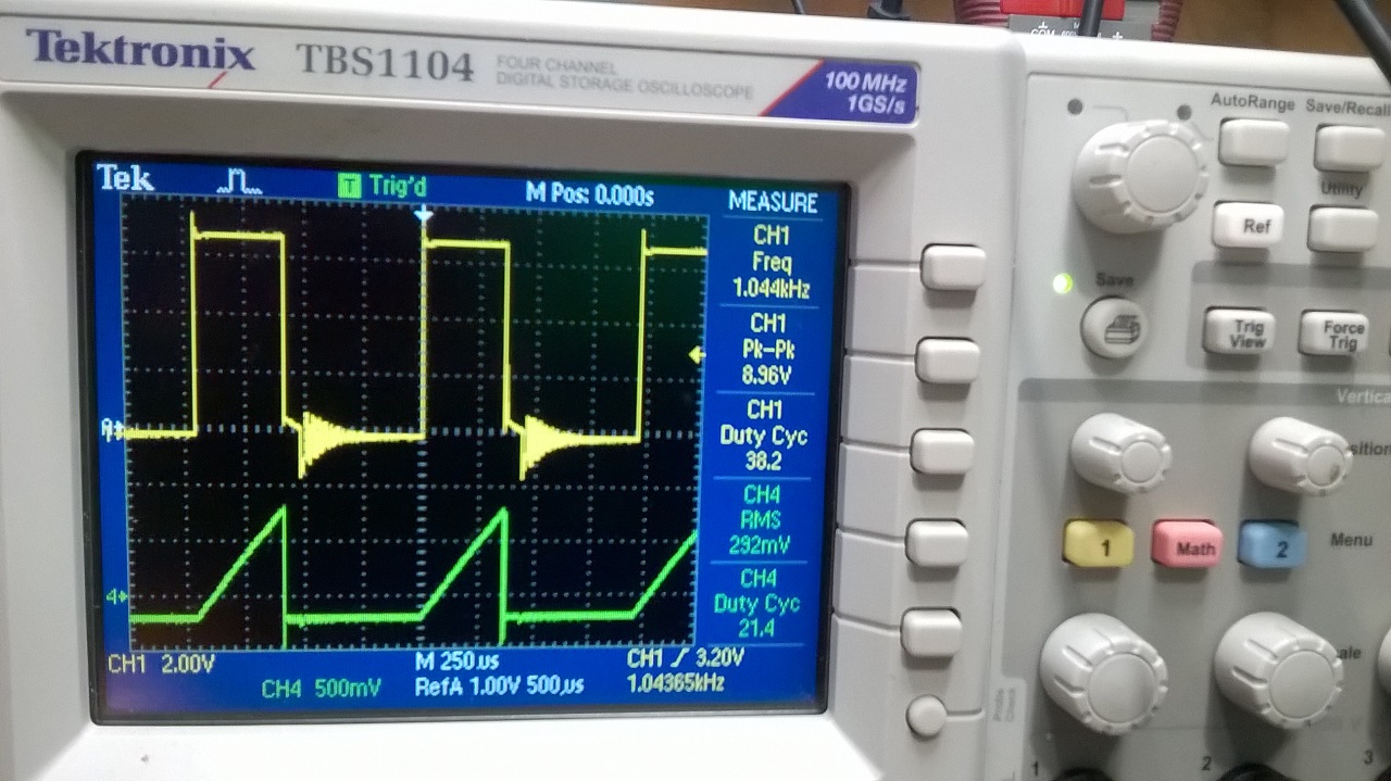
That "rediculously slow charging of an inductor and a normal tranformer action" is exactly the same as the current shape shown in Jagau his screenshot, as that is what i replicated.
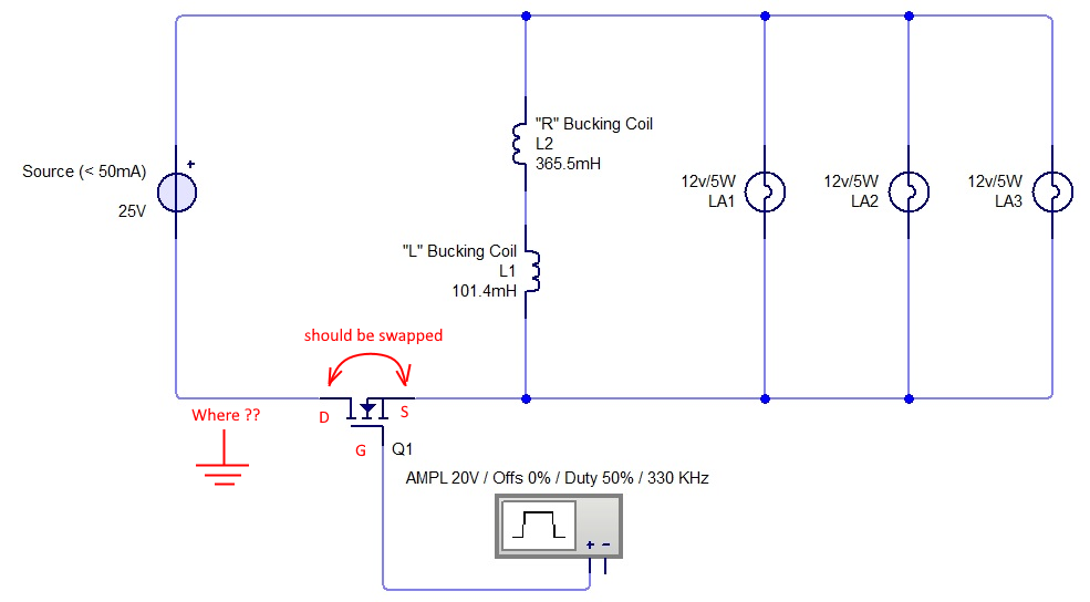
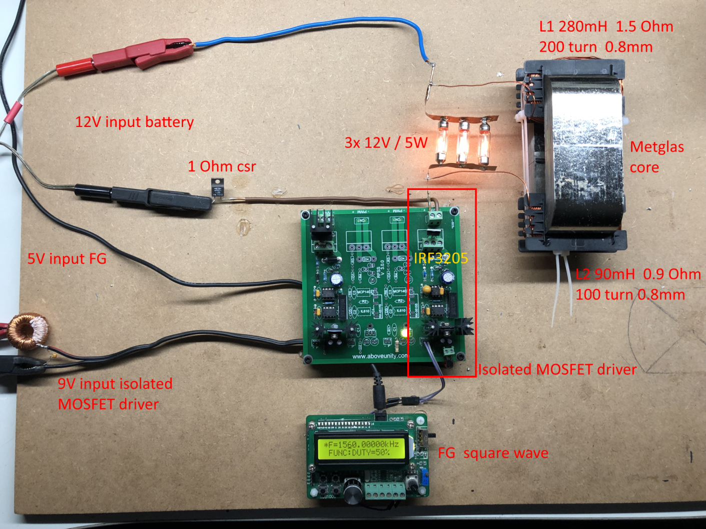
And NO, the 1 ohm resistor in the supply can NOT be the "blatantly obvious reason" because as i mentiond before, i only use the 1 Ohm csr to double check my current probe.
There is no 1 Ohm csr in the circuit.

I used the same 120V / 4W  bulb as Jagau and that is causing this "rediculously slow charging" current shape as with the normally used 12V 5W and 12V 21W bulbs its square shaped.


Concerning the general ZPM replication.

You say we are NOT looking for LC resonance, but i think that is just the whole point of the ZPM, we need to be in LC resonance, look at the original ZPM thread from Fighter, there you see all kind of resonance like signals (the Graham Gunderson signal is it already called).

OK about the pulse switch time, i can see it should be fast / sharp, but i use what Fighter has used, so i should have about the same fast / sharp pulses as he has.

I do agree about the saturation of the core, i tried to saturate it, but i can't, so it will probably not be needed to get the effect.

I will rewind my coils to 150 / 300 turns and start over again with my experiments and low duty cycle.

Thanks Itsu 

Itsu posted this 12 December 2022

Quoting:Atti

As mentioned before and showed on one of my video's, i do see a reduction in input current to about 0mA around (parallel) resonance (resonance only with a PS or filter, NOT when using a battery), but also, then the bulbs go out 

Itsu.


I bought a 12V car battery and an 18V screwdriver battery. I lined this up. (Chap4. video) The effect occurs in the same way.
What could be the explanation?


If you start with modifications or other components connected to it it's hard to guess which of those are modifying ZPM's behavior.

I have been making the same mistake for several times. Because I didn't perform the tasks according to the specified parameters and not according to the specified material quality (because I didn't have the right material) And I didn't succeed. Of course. Everything takes time and money. But if you have a way to do it (because there is a larger Amcc core!) do it using the original method. Jagau and Chris (published on the other forum) got good results with some modifications. But problems with measurement have been reported. Personally, I therefore do not deal with the importance of measurement. I only take it as information for further fact-finding.

Then I had an idea and tried again. I'm starting all over now to understand.

But as he said: everyone does what they want with their free time.


Atti.

Hi Atti,

Do you use the filter circuit with the batteries?   

If so, then it comes from the filter circuit, i had the same with my battery, without any filter no resonance, but with filter i got some resonance points somewhere.

If you use the batteries without your filter with the same effect then i do  not know, perhaps because your circuit is slightly different as the "normal" ZPM it matters somehow.

I did try to replicate Fighters ZPM as close as possible, only difference is the amount of wire which will be corrected soon, then we start over again to test this baby.

Regards Itsu


Vidura posted this 12 December 2022

Just some thoughts I would like to share. If we think in an LCR resonant circuit, a standing wave will manifest with the potential antinode at the capacitor. Al PS have at least one filter capacitor built in. The difference with the battery(directly connected) is that it works as a floating grounding, which would tie the current antinode to this location. The battery acts as a source and sink of charges in that case. If so, for battery operation it would be required to decouple the circuit with a filter and  a capacitor on the device side. Regarding the failure of replication I don't think that it is an issue of switching, as Fighter did it with IRF250 driven directly from the SG, and also with the isolated switching module with dedicated driver IC and CREE SIC-MOSFET, and both worked for him. The issue is most likely the physical layout of the inductors or/and the connecting wires and PS.

Vidura

  • Liked by
  • Fighter
  • Inception
Shelfordella posted this 13 December 2022

Quoting:Itsu

Quoting:Shelfordella

It looks good if V x I are instantaneous products, or V(t) x I(t), which is the same as Pavg=Vrms x Irms x pf. I guess yellow is the power supply voltage instead of the voltage pulse towards the inductor.

Shelfordella,

V x I ARE instantaneous products.

As i mentioned earlier, the scope math function does NOT use rms, avr (mean) or p2p values, it uses the instantaneous values of the traces (at a miljoen points on the screen or so) and takes the average (mean) of those products arriving at the 717mW.

Yes, yellow is the power supply voltage at the PS (input to the device), as that is what we want, the input power into the device, not somewhere inbetween.

Thanks,  Itsu

Hi Itsu,

you need to plot the voltage that causes the current to determine the power that goes into the component like an inductor, or take from the scope of a sawtooth delta I / delta t x L this should give the Voltage too.

"A little theory and calculation would have saved Edison 90 per cent of the labor." Nikola Tesla

  • Liked by
  • Inception
Itsu posted this 13 December 2022

Quoting:Vidura

Just some thoughts I would like to share. If we think in an LCR resonant circuit, a standing wave will manifest with the potential antinode at the capacitor. Al PS have at least one filter capacitor built in. The difference with the battery(directly connected) is that it works as a floating grounding, which would tie the current antinode to this location. The battery acts as a source and sink of charges in that case. If so, for battery operation it would be required to decouple the circuit with a filter and  a capacitor on the device side. Regarding the failure of replication I don't think that it is an issue of switching, as Fighter did it with IRF250 driven directly from the SG, and also with the isolated switching module with dedicated driver IC and CREE SIC-MOSFET, and both worked for him. The issue is most likely the physical layout of the inductors or/and the connecting wires and PS.

Hi Vidura,


nicely put, so at the PS (capacitor) we will have the antinode as being shown here (taken from:  https://en.wikipedia.org/wiki/Node_(physics)):

A standing wave. The red dots are the wave nodes


A battery will dampen or even, without having a capacitor, prevent the resonance and standing waves, thus the effect, to occur.

Concerning the switching, i, like Fighter used several different switches (MOSFETs) and switching methods, and it made no difference for Fighter to see the effect, and for me to not see the effect, so indeed, i think the switching is important, but not that critical.

So yes, i also think the physical layout of the inductors or/and the connecting wires and PS are the key factors here ๐Ÿ‘

Itsu

  • Liked by
  • Inception
  • Vidura
Itsu posted this 13 December 2022

Quoting:Shelfordella

 Itsu,

you need to plot the voltage that causes the current to determine the power that goes into the component like an inductor, or take from the scope of a sawtooth delta I / delta t x L this should give the Voltage too.

Hi Shelfordella,

thanks,  but i don't think you can cipher out one component (inductor) and use the power into that single component to calculate the input power for a whole device.

We need the whole circuit being powered especially here where it seems that the PS itself is an active part of the device, in fact, i think we might need to start measuring the input power from even before the PS if that is even possible in a practical way.

We will have no output in the first place if we exclude the other components and its losses etc., they are needed for the device to function IMO.

Regards Itsu

  • Liked by
  • Inception
  • Vidura
Fighter posted this 13 December 2022

Quoting:Itsu

Hi Shelfordella,

thanks,  but i don't think you can cipher out one component (inductor) and use the power into that single component to calculate the input power for a whole device.

We need the whole circuit being powered especially here where it seems that the PS itself is an active part of the device, in fact, i think we might need to start measuring the input power from even before the PS if that is even possible in a practical way.

We will have no output in the first place if we exclude the other components and its losses etc., they are needed for the device to function IMO.

Regards Itsu

There we go again...

What about measuring the energy of your building's power lines and their losses, because they're part of the circuit too ?...

No you don't, for the real COP of the device you need what it's receiving on its input, just the energy in the square pulses.

Finally you got it.

That is the correct approach. 'Cause maybe my switching circuit for now is not that efficient and it dissipates some energy as heat. That doesn't mean the ZPM is consuming that energy. All what ZPM (or any other DUT) is consuming is the energy contained on the square pulses it is receiving on its input. So you find the real/constant COP of the ZPM/DUT.

Else you can go into a ridiculous situation where with one less efficient switching circuit (wasting energy in a lot of heat) you get a COP of let's say 3 and after you make a more efficient switching circuit (let's say this one is running cold, without wasting energy in heat) to see actually the COP  of the ZPM/DUT jumps to let's say 3.5 or maybe 4. That's not how the COP is measured, you want to know exactly the energy on the input of the device (those square pulses) without involving the energy wasted in the switching circuitry or any other energy. Just what the device "see" on its input.

So I'm glad you understood what we're calculating and why for input we're using Jagau's calculation method for square pulses.

Is this how you calculated the COP for other replications too ? If your switching circuit is not efficient so let's say it's dissipating 30W through radiators in heat you consider the DUT is consuming those 30W ?! The DUT is consuming 0 of those 30W ! Build a very efficient switching circuit (let's say it's running cold) and guess what, the COP you calculate this way will be with 30W bigger ! This is not the correct method to calculate the COP of an DUT !

Fighter

"If you want to find the secrets of the universe, think in terms of energy, frequency and vibration."
Nikola Tesla
  • Liked by
  • Inception
bigmotherwhale posted this 13 December 2022

I dont want to upset you Itsu im trying to help but when you say you have the same as jagau im not seeing it. 

These are the two images i saw, one shows a flat sawtoooth with a very sharp transient shown by the shap peak on the end of the switch and the other is curved with no transient or ring down after the switch. Why is this? am i not looking at the right pictures here. 

There is clearly an effect here. 


  • Liked by
  • Fighter
  • Inception
Vidura posted this 13 December 2022

Quoting:Itsu

Quoting:We need the whole circuit being powered especially here where it seems that the PS itself is an active part of the device, in fact, i think we might need to start measuring the input power from even before the PS if that is even possible in a practical way.

This makes sense regarding measurement techniques, and as it is a switch mode PS it can be powered with DC on the input, so it would be a reliable data if rectified and filtered before the PS. Of course the unloaded consumption coud be substracted also๐Ÿ˜‰.

Vidura

  • Liked by
  • Inception
Close