Are you still continuing with that "measurement error" ?..
How many are needed to confirm Jagau's calculation method so you can get over it ? 4 ? 5 ? 6 ? More ?
You got another one here:
His calculations for Pin are correct.
292mv =292 ma
His output measurements with the multimeters are also correct because they are true rms.
https://www.redcrab-software.com/en/Calculator/Electrics/Saw-Tooth-Voltage-RMS-Value
https://masteringelectronicsdesign.com/how-to-derive-the-rms-value-of-pulse-and-square-waveforms/
√3 or √1/3 is used for sawtooth rms, √(DC) or √1/DC for rectangle rms.
VP = VRMS × √2
And another one:
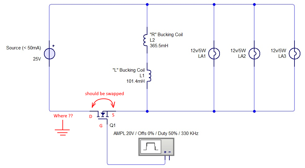
From what Jagau states, the current reading you need is the peak amps (or saturation current), then you can apply the formula:
P= I x V x sqrt(Duty_Cycle) / sqrt(3)
The peak amps is the point/tip of the triangle, the math handles the rest. So you'll need to get that measurement and have another go at it. Just make sure the triangle waveform has a pretty much linear top to it. If it starts to round off, the math won't be quite as accurate.
I told you this calculation method was verified and confirmed by other members of our core team before Jagau came public with it. Including Yoel. Jagau is a very careful researcher. He asked for double-checks here and also the experts in real life before deciding to move the info in our public section. I'm not expert but I also checked his calculation method with the results of the calculator from Vishay site. The results always matched.
So get over it, I know you are against Jagau for other reasons but this obsession with "measurement errors" which are not there is getting ridiculous.
And you're pushing the limits we have here about tolerance and about no personal attacks. Be very careful. Just my advice.
what i do with my time is indeed entirely up to me, and i did not "demand" anyone to come to my thread and waste their time there.
You are perfectly free to ignore me and my thread and do what you have to do with your time.
So you think if you keep continuing those personal issues you have against Jagau in your own thread everything is okay and admins should just ignore that ? I think you don't realize this is not the overunity site, "you're not in Kansas anymore !". Of course admins will react, and when we see toxicity or personal attacks here we mean business, we'll not just watch. Be aware of that else you'll get banned very fast, you'll not even see it coming.
How i approach a replication is also entirely up to me
I saw that and it's a wrong approach.
When I start a replication I follow the inventor's specs very close. If the inventor says he use a DC source for sure I don't start with a battery. If the inventor says he use 150/300 turns I start with that because, I don't know, maybe it's significant for the functionality of the device. Could not be important and the device could work with 100/200 too but if the inventor didn't tried that it's better to go to the safe way and go as close as possible with the details of the prototype.
When the replication is successfully then it's another story, you can start modifying things the way you like and checking the device is still working after every modification you make.
This is the correct approach.
I know what Jagau (and you now apparently) are trying to do by trying to calculate the power in the pulse (square) AFTER the MOSFET switch.
Jagau did that in his Melnichenko thread too, which is fine to do, but that is not the way if you want to know the COP of your device.
Finally you got it.
That is the correct approach. 'Cause maybe my switching circuit for now is not that efficient and it dissipates some energy as heat. That doesn't mean the ZPM is consuming that energy. All what ZPM (or any other DUT) is consuming is the energy contained on the square pulses it is receiving on its input. So you find the real/constant COP of the ZPM/DUT.
Else you can go into a ridiculous situation where with one less efficient switching circuit (wasting energy in a lot of heat) you get a COP of let's say 3 and after you make a more efficient switching circuit (let's say this one is running cold, without wasting energy in heat) to see actually the COP of the ZPM/DUT jumps to let's say 3.5 or maybe 4. That's not how the COP is measured, you want to know exactly the energy on the input of the device (those square pulses) without involving the energy wasted in the switching circuitry or any other energy. Just what the device "see" on its input.
So I'm glad you understood what we're calculating and why for input we're using Jagau's calculation method for square pulses.
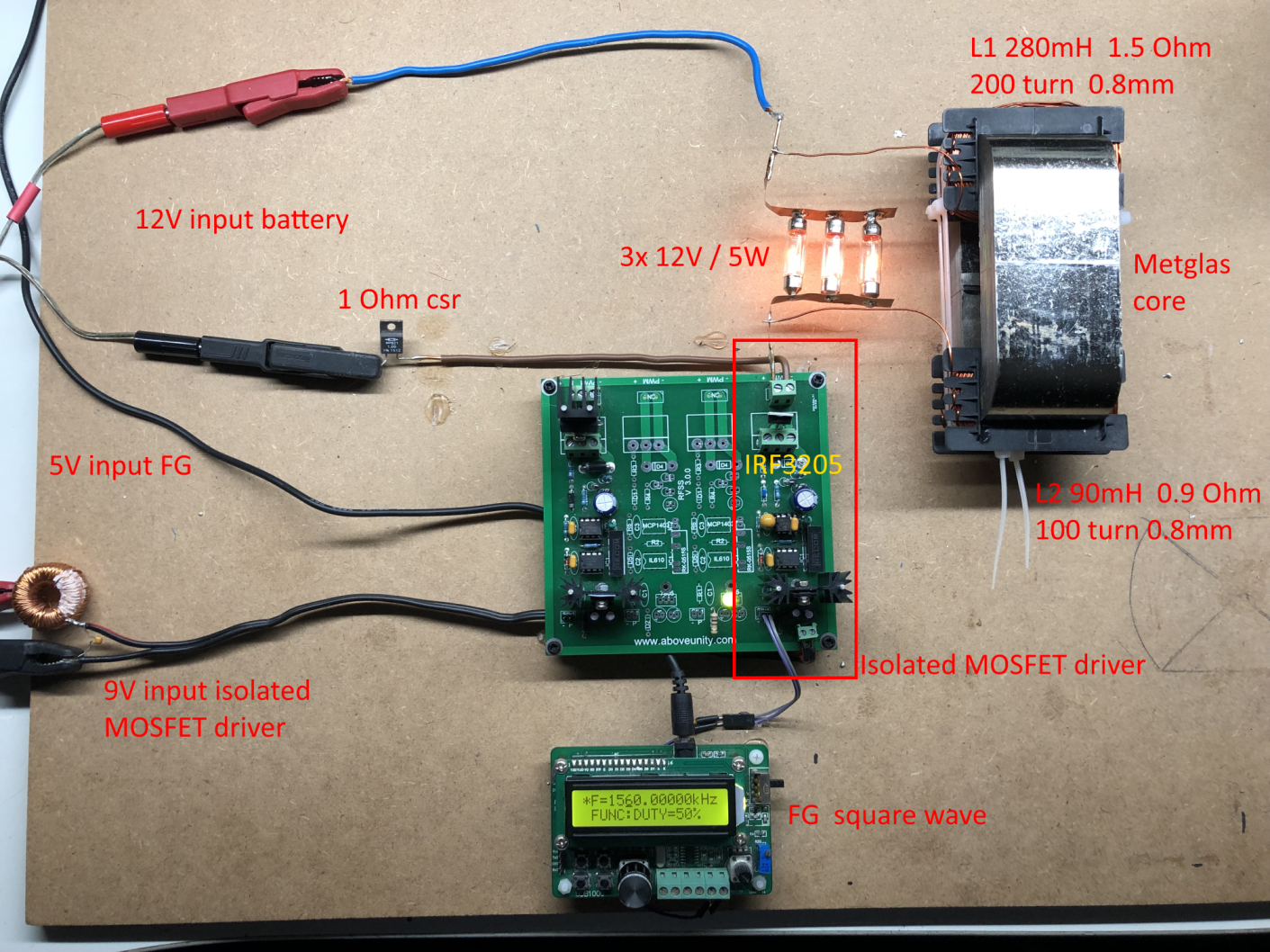
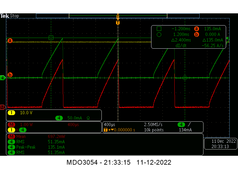
Unfortunately Itsu all that scope shot shows is a rediculously slow charging of an inductor and a normal tranformer action, and looking at your setup its plainly obvious why, the 1 ohm resistor in the supply being a blatantly obvious reason for one.
...
You need to go back to the basics
...
You are attempting to measure something you havent even got by the looks of it.
BMW is right, you know. I refered to Don Smith (I don't remember if here or in our initial private messages exchange) that any resistor or capacitor connected to a coil will lower its resonance frequency away from its natural resonance frequency. It will still have a resonance frequency but that will be artificial so to speak because of resistor/capacitor. That's why I never put a shunt resistor on the coils to measure current there. I prefer to let the coils "dance" at their natural resonance frequency. I just used the voltage probes from time to time to get and idea of how the coils are "dancing" and I told you how by checking just the voltage I can get a pretty good idea what the current and magnetic fields are doing inside ZPM.
If you start with modifications or other components connected to it it's hard to guess which of those are modifying ZPM's behavior.
Let the coils free without resistors and stuff, when you'll get the input decreasing effect then you can try to make any modifications you want like place shunt resistors, try to make it run on battery (which from my experience will not work for the reasons I explained already) or anything you want to do.
But until then just follow the data from the previous ZPM presentations. Those made by me or by Atti or by Jagau, doesn't matter which one, all are valid presentations of working ZPM replicas.
And don't get frustrated, ZPM may look simple but what's happening inside it is not simple at all. You're looking at a zero-point / vacuum / aether (however you want to call it) energy pump. Don Smith described his devices like this, Bearden used the same phrase. Classical physisics can't describe it or any other devices like this no matter how hard anyone try to enforce it on these devices. Maybe quantum physiscs (which is now in its infancy but already shocked the scientists many times, see the particles entanglement and their "spooky" as Einstein called it action at distance) could in the future explain with exact details how these devices work. That's what Yoel is studying and is very interested in.
I did came public with the ZPM exactly for that purpose, so other researchers replicate it and then to work together on improvements. Unfortunately all these events in the last years forced me to temporary change my priorities and I don't have time to continue the experiments for now but it's temporary, I'm still here and I'm looking forward to make the things change and to have time again for continuing with ZPM and other projects (like Aharonov Bohm experiment and restarting my replication of Bearden's MEG as now I have more information I didn't had before.
Well, that's it for now, going to sleep for a few hours because tomorrow another week of work starts.
Have a nice day / evening everyone
Fighter
| "If you want to find the secrets of the universe, think in terms of
energy, frequency and
vibration." |
|
|
Nikola Tesla |