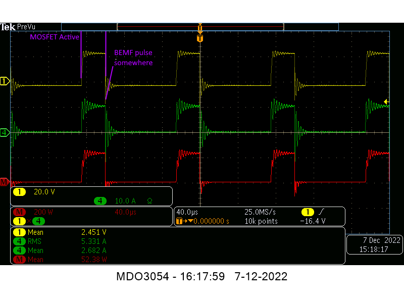
so somewhere we loose 14W
...
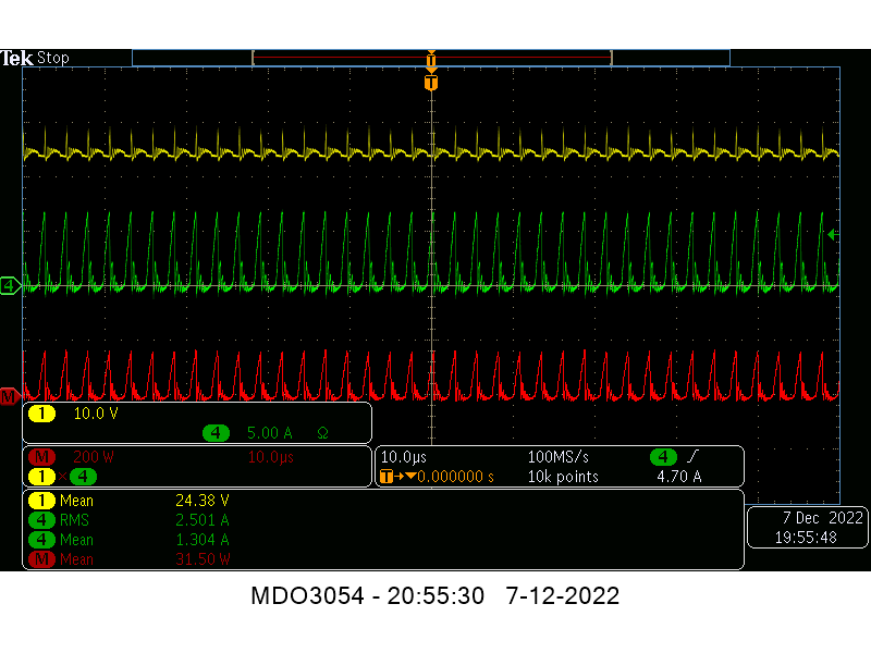
so somewhere we loose 26.6W
...
I think these values show pretty accurate what power is going into the ZPM, and that the Voltcraft shows somewhat more then there is; roughly between 5 to 10% more.
On the upstream power supply analysis, I think you are right in the ballpark as well. Seems to me you have acquired the data, reduced it and we can see pretty clearly where the power is coming from.
Are you guys kidding ?..
You say the light bulbs are 57W, a difference in measurement of 26.6W is closing to 50% ! What "5 to 10%" ?
When you have 50% error in measurements that's not a "yeah, sounds about right" situation, that's a failed measurement. At least that's how I consider it when I'm in that situation. That percentage should tell you there is something very wrong with that measurement. It's like my powermeter shown to me that my DC source was providing more power that it can actually provide. That's why that was a failed measurement too. Probably because it's a switching power supply (see the quote below) ?
And what happened with:
If it's a switching power supply as I suspect it is, the rectification diodes may put a significant amount of noise on the line.
The "significant amount of noise" just dissapeared and everything is okay now ?
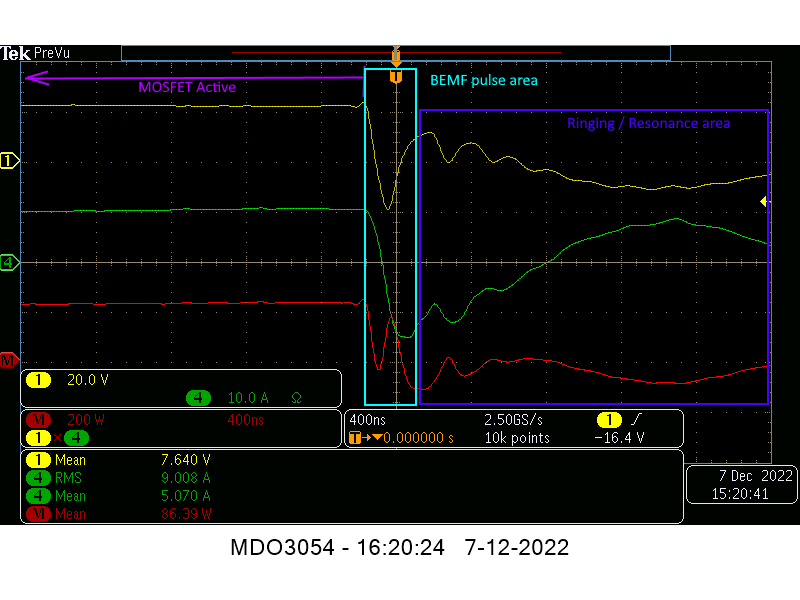
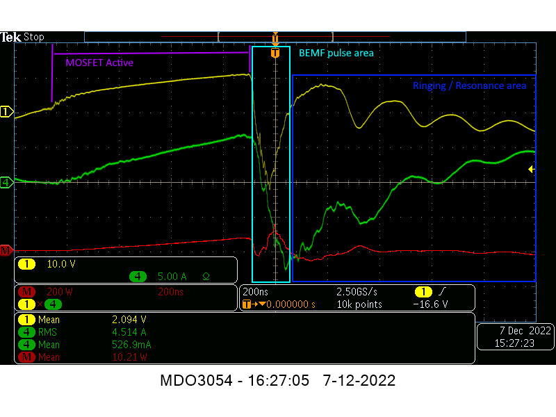
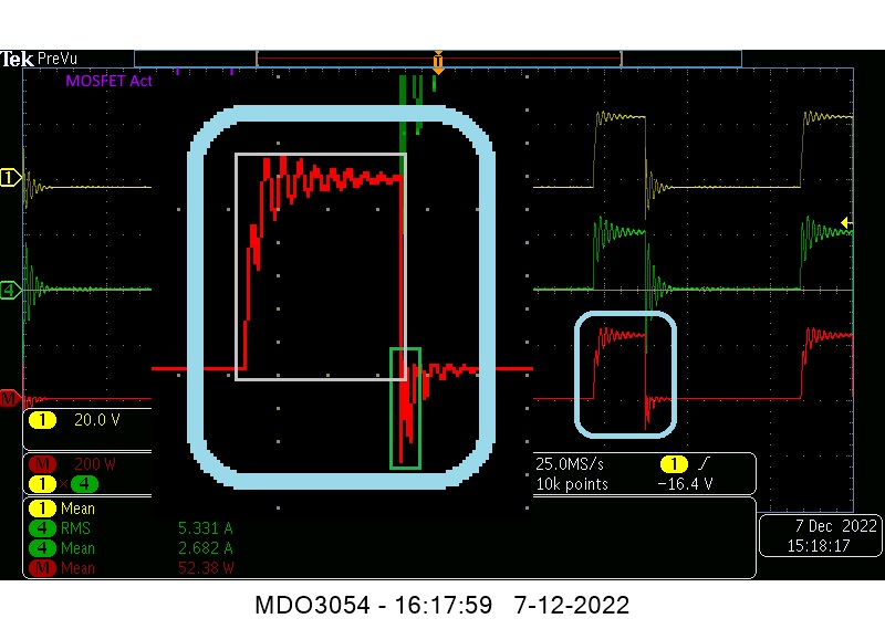
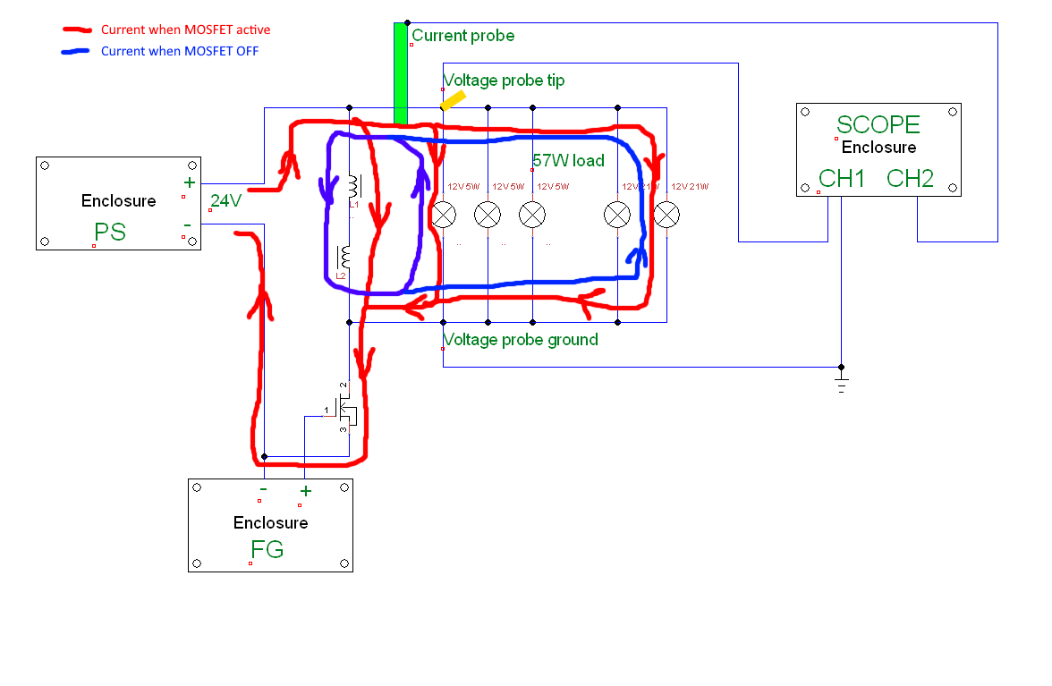
You have visualy the situation right in front of your eyes:
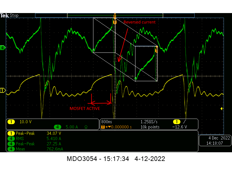
Look at the projected input area over the output area while the MOSFET is off !
I projected it lower so you can compare the two areas. Everything you see around the projected area is energy produced while the MOSFET if off ! And no, that's not "looks impressive but is no real power", seriously, we can't just invent "rules" like that when we need them to contradict what everyone see.
Itsu, the initial question was why your replication doesn't produce the input reduction effect I presented so many times and which was also presented by Atti in his successful replication. Instead of that we entered in an endless "measurement error" discussion just like it's happening on overunity site for so many years, that being the cause why there is no progress for, I don't know, 10...15 years ? Everyone there is struggling not to see the results but to enforce every device presented there to fit in the "measurement error" scenario.
Isn't it right, Munny ? I don't know, your name sounds familiar, are you from overunity site ? Didn't checked, just asking.
Seriously, when I see measurements errors of almost 50%, tens of wats more or less in measurements and phrases like "Seems to me you have acquired the data, reduced it and we can see pretty clearly where the power is coming from" I feel like I'm just wasting my time trying to assist with the replication.
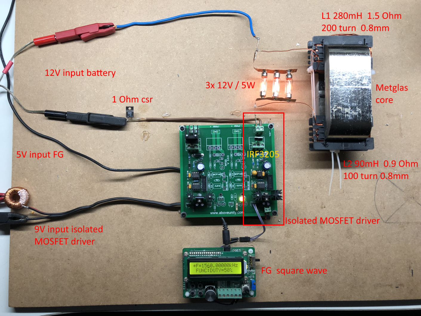
I do notice that the MOSFET is heating up quickly at 378kHz, so i assume that that would be one of the major losses (also reported by Fighter) i guess.
Even with those loses my input is still in miliamperes which is not the case here.
So for now I presented my evaluation, I shown the difference between the consumed energy and the produced energy visually on Itsu's scope and no, "looks impressive but is no real power" is really not a valid argument to dismiss the power produced by a variating magnetic field for 75% of the time while the MOSFET is off. That is real power making the light bulbs shine while the MOSFET is off.
Anyway, you guys let me know when the "measurement errors" discussion ends so, maybe, we can try to find out why the input reduction effect is not present in this case like I presented or Atti presented and to find out what's blocking it.
Until then you may also take a look on a calculation method I agree with presented by Jagau, a very experienced member of our core team:
https://www.beyondunity.org/thread/energy-in-a-pwm/
Jagau is telling you with documentation and details what I'm trying to show you on that scope image. That's how you manually calculate the real input power based on input voltage, current, frequency and duty-cycle.
In the Jagau's thread you will find out there is even a calculator online on Vishay's site, that's a very big/professional manufacturer of electronic components I'm sure everyone knows:
https://www.vishay.com/en/resistors/pulse-energy-calculator/
Try it, probably you'll be surprised/shocked but then you'll start to see what I'm showing on Itsu's scope.
Have a nice day/evening everyone.
Regards,
Fighter
| "If you want to find the secrets of the universe, think in terms of
energy, frequency and
vibration." |
|
|
Nikola Tesla |