Fighter's ZPM (Zero Point Module) failed replication by Itsu

  • 8.1K Views
  • Last Post 18 December 2022
Itsu posted this 07 November 2022

Hello all,

i opened this thread to discuss my replication of Fighter's ZPE (Zero Point Module).

I already opened a similar thread on OUR.com (https://www.overunityresearch.com/index.php?topic=4374.msg101654#msg101654 ), but will transfer some data from there to here.

Initially i understood that the below diagram was correct and complete, but it turns out its not.
There is a ground connection somewhere, but i am not sure where it is exactly, hopefully someone can tell me.
The MOSFET is shown wrong as the Drain and Source should be swapped, which was corrected later in Fighter his thread so therefor the mentioning in red.

I have build up a similar circuit and the data is shown here: 
(Be aware that the induction measurement was done at 10kHz, but due to the influence of the metglas core it can be (and is) completly different on other frequencies, see my thread on OUR.com for a VNA scan of the coil/core)


I am using a 12V battery for now as my PS (minus NOT grounded) was acting weird due to all the pulses coming back from the ZPE device.
Up till now no special effects or resonance in a 0 to 5MHz range are seen with this setup, but as said the grounding may be the problem here.

Itsu

Itsu posted this 10 December 2022


Fighter,

With "boundaries of error margins" i mean the tolerances our measurement equipment has, like f.i. the delay between voltage and current probes.

My A6302 current probe has a nominal propagation delay of 30ns which should be compensated for else there are measurements possible with wrong (within margin) results.

Here a screenshot of my scope showing how it compensates for the delays between the different probes i use:

Other scopes have similar settings or need to set it manual.

Another example is the use of a csr (like 0.1 Ohm) in higher frequency circuits where the always present inductance of such a csr will have a reactance adding to the csr resistance (total impedance) and therefor again invalidate (within margin) the result.

Several of such margins can add up and lead to wrong results.

Concerning your COP = infinite,  OK,  let’s agree on COP = 100 then.

Itsu

  • Liked by
  • Inception
  • YoElMiCrO
Fighter posted this 10 December 2022

Quoting:Munny

On the upstream power supply analysis, I think you are right in the ballpark as well.  Seems to me you have acquired the data, reduced it and we can see pretty clearly where the power is coming from.

Great ! Exactly the "conclusion" someone is looking for ! Let's just a ignore a "small" detail: the real ZPM's input reduction effect is not present. Excepting that, the measurements are very "relevant" and helpful for the "conclusion" we're looking for, isn't ? šŸ˜‰

How convenient...

So case solved and closed, we all can go home now !

Fighter

"If you want to find the secrets of the universe, think in terms of energy, frequency and vibration."
Nikola Tesla
Itsu posted this 11 December 2022

All,

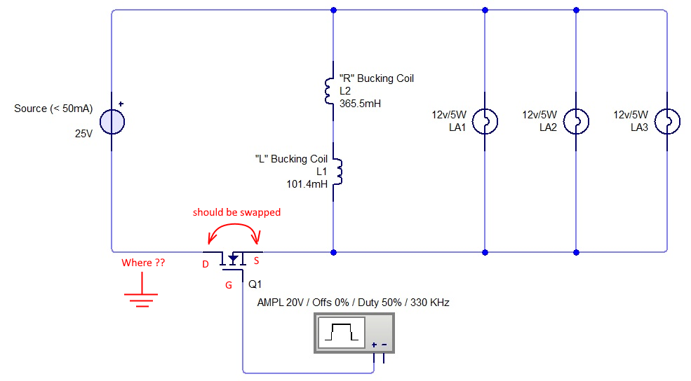
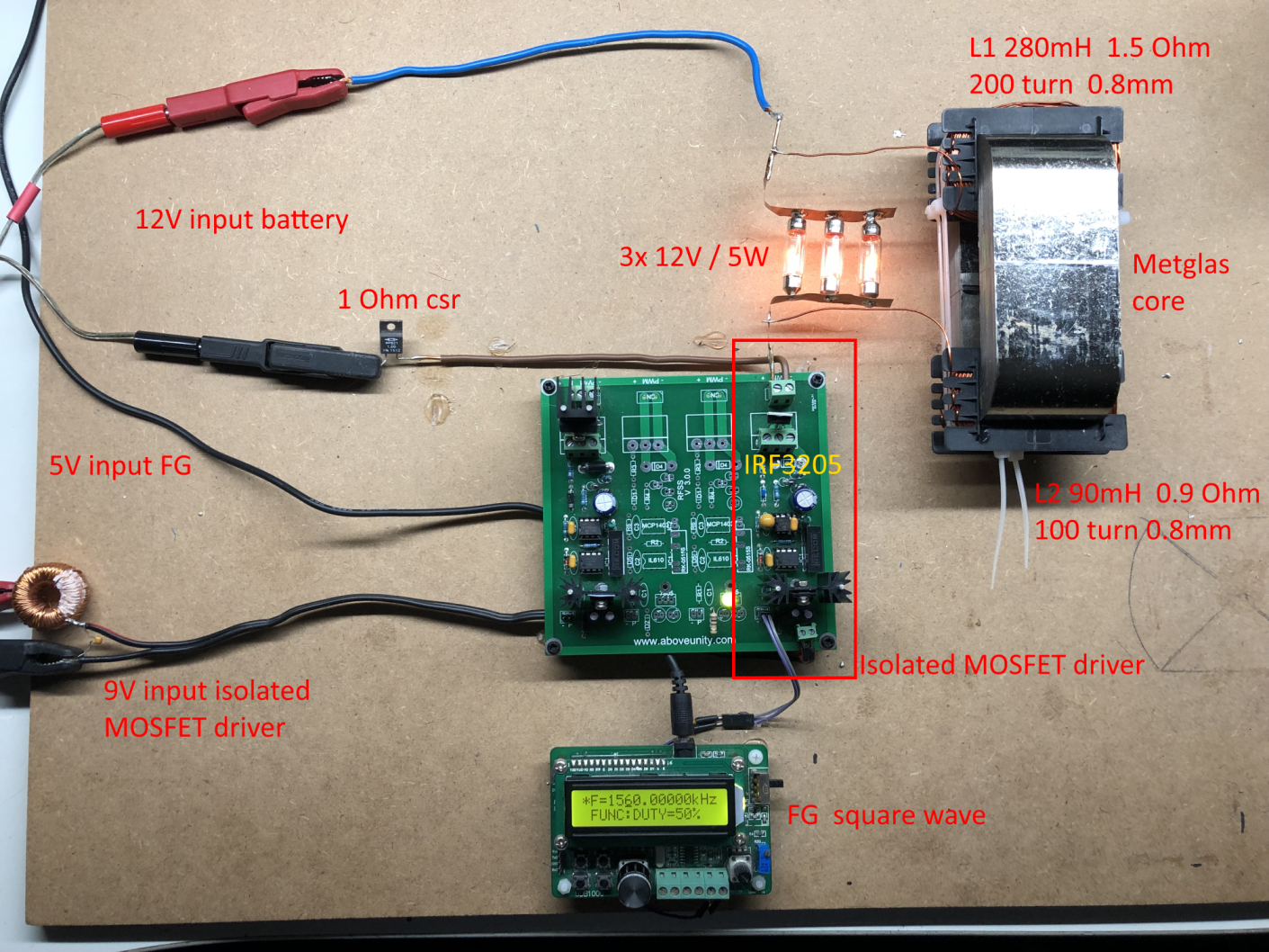
I made a quick replication of Jagau his setup using a similar single 120V / 4W bulb as load like Jagau and setting the FG to 1kHz @ 38% duty cycle.

The bulb is not brightly on, but pulls 536mW.

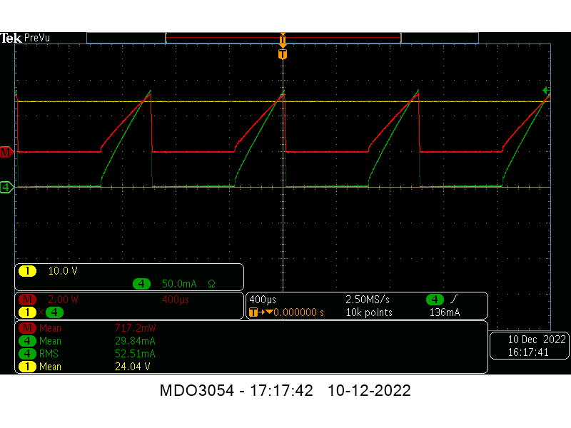
The result can be seen in the screenshot:


So, i have:

24V DC input directly across the 24V PS, yellow trace,

52.5mA rms triangle shaped pulsed DC input directly taken from the minus lead of the 24V PS,  green trace            (also note the lower 29.8mA average current).

Power input calculated via yellow x green, red trace.


When using Jagau his formula Pin = I x V x SQRT(Duty Cycle) / SQRT(3T) i get: 

Pin = 0.0525 x 24 x SQRT(380) / SQRT(3000)             (380us Duty cycle, 1000us Frequency)

Pin = 0.448mW.


So, with the 536mW output in the bulb i have a COP = 1.2 here!!


But looking again at the screenshot, we also see the instantaneously calculated power using the math function Voltage (yellow) x current (green) being 717mW   (the scope does NOT use rms nor mean nor p2p values here).

We also see the average current being 29.8mA and the average voltage being 24V, so as both being (pulsed) DC we can multiply these to get the Power being also 715mW.

Calculating the COP now shows we drop to COP = 0.75.


So where does that difference between calculated power (448mW) and via the scope measured / calculated power (717mW / 715mW) comes from?


My interpretation is that the used formula uses the "frequency / Duty cycle relation" twice.

Once in the formula itself (right part), and once already imbedded into the used Irms value, let me explain.

The formula presented here, https://masteringelectronicsdesign.com/how-to-derive-the-rms-value-of-a-triangle-waveform/   (specially tailored for triangle shaped (the current) signals)  shows as formula (4) this:

Irms_triangle = Ip SQRT t1/3T.


It means that we calculate Irms from Ipeak using this frequency / duty cycle relationship, so let’s do that to see if we get the same Irms:

Ip = 138.6mA, so Irms = 0.1386 x SQRT 380/3000   =  49mA rms, which is very close to the 52mA rms on the scope.

So, if Irms already has this freq. / duty cycle relation inside it, we should not again do that in the above formula from Jagau, so there for i think this formula is wrong.

This formula is also not needed IMO as we, as shown above, are dealing with DC and triangle pulsed DC signals only for which we can simply multiply the average Voltage and average Current values.


Here i ask Jagau to put up on his scope the average voltage on CH1 (24V) and the average current on CH2 again and use the math function CH1 x CH2 to show the calculated power on input or simply multiply the average current value with the average voltage value to get the input power.


I invite every member of this forum skilled or not to explain the difference seen between the calculated by formula input power and the measured / calculated by the scope input power and which of the 2 methods is the correct one. 

Thanks,   Regards Itsu

Fighter posted this 11 December 2022

As I told you in our exchange of messages, use Jagau's formula to a set of parameters then use the calculator for the same parameters here:

https://www.vishay.com/en/resistors/pulse-energy-calculator/

You'll see the results are the same.

But you keep looking for "measurement errors" which are not there.

The energy we send to our devices is shaped as short square pulses. And we calculate the energy in those square pulses.

Take your time to read again:

https://www.beyondunity.org/thread/energy-in-a-pwm/

Just like you did with ZPM, instead of trying to replicate and fix the issues why a replication doesn't work, you keep hunting for "measurement errors". I suppose it's an old habit from the overunity site 'cause there that's all they do, they don't do real research and experiments.

You had a video demonstration of the input reducing effect but instead of comparing your replication with my presentation or Atti's presentation to see what's blocking that effect in your replication you waste your time hunting for "measurement errors" which are not there.

You may have a lot of time to do that but most of us here have a very limited time which we don't want to waste on useless and endless discussions about "measurement errors" typical to the overunity site.

So what you do with your time is up to you but don't expect us to waste our time in that kind of discussions.

As I understand Jagau already gave to you all the explanations in previous long discussions. If you don't agree with those explanations then it's your problem, it's not his obligation or anyone's obligation to make you believe or not those explanations.

Just because you don't agree with something that doesn't mean that something is not real.

My advice: stop wasting other members' time with things like this, instead work on fixing the issues in replicating the things you saw with your own eyes in our demonstrations.

Regards,

Fighter

"If you want to find the secrets of the universe, think in terms of energy, frequency and vibration."
Nikola Tesla
Munny posted this 11 December 2022

Quoting:Itsu

Pin = 0.0525 x 24 x SQRT(380) / SQRT(3000)             (380us Duty cycle, 1000us Frequency)

So where does that difference between calculated power (448mW) and via the scope measured / calculated power (717mW / 715mW) comes from?

Itsu,

From what Jagau states, the current reading you need is the peak amps (or saturation current), then you can apply the formula:

P= I x V x sqrt(Duty_Cycle) / sqrt(3)


The peak amps is the point/tip of the triangle, the math handles the rest.  So you'll need to get that measurement and have another go at it.  Just make sure the triangle waveform has a pretty much linear top to it.  If it starts to round off, the math won't be quite as accurate.

Fingers crossed you'll start to see something similar to the other ZPMs already documented.  I'm counting on you, so I can get motivated and build one also.


  • Liked by
  • Fighter
  • Inception
Itsu posted this 11 December 2022

Fighter,

what i do with my time is indeed entirely up to me, and i did not "demand" anyone to come to my thread and waste their time there.

You are perfectly free to ignore me and my thread and do what you have to do with your time.

How i approach a replication is also entirely up to me, but i always am open to suggestions, but if those suggestion do not provide any usefull insights i put them aside, but believe me, i always look (and have done also with this replication) at every possible angle, i still am.

I did follow the link to Jagau's "energy in PWM" thread, in which i even commented and included an LTspice simulation which is being ignored and pushed aside by telling me he is to polite to answer me and don't want to waste time.  
Why start a thread then if you have no time for discussions?


I know what Jagau (and you now apparently) are trying to do by trying to calculate the power in the pulse (square) AFTER the MOSFET switch.

Jagau did that in his Melnichenko thread too, which is fine to do, but that is not the way if you want to know the COP of your device.

Then you need the INPUT power versus OUTPUT power and the INPUT comes from the Power Supply, not somewhere halfway the circuit IMO.


Anyway,  my advice: stop looking at my thread so you don't waste any time on it.

Regards Itsu  

Itsu posted this 11 December 2022

Quoting:Munny

Quoting:Itsu

Pin = 0.0525 x 24 x SQRT(380) / SQRT(3000)             (380us Duty cycle, 1000us Frequency)

So where does that difference between calculated power (448mW) and via the scope measured / calculated power (717mW / 715mW) comes from?

Itsu,

From what Jagau states, the current reading you need is the peak amps (or saturation current), then you can apply the formula:

P= I x V x sqrt(Duty_Cycle) / sqrt(3)


The peak amps is the point/tip of the triangle, the math handles the rest.  So you'll need to get that measurement and have another go at it.  Just make sure the triangle waveform has a pretty much linear top to it.  If it starts to round off, the math won't be quite as accurate.

Fingers crossed you'll start to see something similar to the other ZPMs already documented.  I'm counting on you, so I can get motivated and build one also.


Hi Munny,

so you say  "the current reading you need is the peak amps"  but that is not what is being done by Jagau.

His scope shows 292mV rms (not Vpeak) and his filled in formula says: 

Pin= 0.292a x 24 x sqrt 0.0.382 / sqrt 3 = 2.533 watts      meaning the 292mV rms current value was used.

In fact the Ipeak is not mentioned in Jagau his posts, but If i use the (estimated) ipeak in Jagau his screenshot of 800mA rms and put that in his formula i get:
Pin= 0.8a x 24 x sqrt 0.0.382 / sqrt 3 = 6.8 watts input.

I don't think Jagau will be very happy with that.

If i use Ipeak in my situation (138mA rms) i get an input of 1.18W, which is now way to high compared with the scope measured 717mW

Thanks,   Itsu


  • Liked by
  • Vidura
Munny posted this 11 December 2022

Hmmm...

What do see when you use the cursors and manually locate the triangle peak?

I'm hoping much less than the scope derived Ipeak.  I would guess the scope would find a max value way high on top of a transient spike, but I could be mistaken.


I will say though, Fighter has the correct approach looking to reduce the input power so that you can focus on an output that is clearly more than the input.  That's the warm fuzzy I would be looking for, then once you get there you can take another look at performance and see just how good it actually is.  I'm not sure what you can do with your coils or core to get things dialed in, but the device is pretty basic so maybe just add or remove a few turns from one side or the other and see if things started trending.  I'd also check the gap and see if there is anything you can do; again look for trends.

If you can get where tens of milliamps are lighting up a couple of automotive headlamps quite brightly, you'll be hooked, then maybe we can figure out how to do this like an assembly line.  I know if you can do it, I can follow your lead and do it too.  If I do it first, it will be an accident and I'll never be able to do it twice.  I just don't have the precision and attention to detail that you do Itsu.  That's why I've always been impressed with your work.


  • Liked by
  • Inception
Itsu posted this 11 December 2022

Munny,

Not sure what you mean by “locate the triangle peak”, you mean with the horizontal cursors of the scope?

I can do that tonight, but i am pretty sure it will show the same 138mA as when i put up the current p2p value (not on the above screenshot due to limitation of the scope to put up only 4 values).

You can now already estimate the 138mA by looking at the green vertical setting of 50mA/div.


Fighter's approach for "looking to reduce the input power so that you can focus on an output that is clearly more than the input", is a solid approach, i agree and that is what i did and do.

I have permanently a voltage and amp meter in the input monitoring it while fiddling with frequency, duty cycle, load (bulbs), gap etc.

As mentioned before and showed on one of my video's, i do see a reduction in input current to about 0mA around (parallel) resonance (resonance only with a PS or filter, NOT when using a battery), but also, then the bulbs go out šŸ™

By the way, watch out when saying this device is pretty basic, it’s kind of touchy here šŸ˜Š, just kidding!!

I received a new spool of 0.8mm wire, so i will be starting to redo my coils to be 150 and 300 turns (now 100 and 200) and wind them the same way Fighter has showed us.

There surely will be some differences in measurements, so hopefully for the better.

I also like your earlier remark about standing waves and use some copper wire to slide along it with a probe to see how this standing wave manifest.

I will try that too, but i doubt the frequency will be high enough to visualize the standing wave with the limited length of wire (i mean 1m wavelength we are talking 300MHz already).

Itsu

  • Liked by
  • Vidura
  • Inception
Vidura posted this 11 December 2022

I also like your earlier remark about standing waves and use some copper wire to slide along it with a probe to see how this standing wave manifest.

I will try that too, but i doubt the frequency will be high enough to visualize the standing wave with the limited length of wire (i mean 1m wavelength we are talking 300MHz already).

This is quite possible, and likely . In Fighters experiments the pattern of standing waves could be clearly observed. It could be attributed to harmonics in the 100rds Mhz range, but I incline more to think that the propagation velocity is greatly reduced due to the core inductanceand distributed capacitance , thus it could happen at much lower frequencies.


Vidura

  • Liked by
  • Inception
Close