The Don Smith Effect

  • 8.4K Views
  • Last Post 5 days ago
Fighter posted this 28 May 2023

In order to not interfere with Jagau's experiments with Dr. Stiffler's SEC technology which have many things in common with what Don Smith named "The Don Smith Effect" I'm starting in parallel with Jagau my own experiments with Don Smith's tech.

If this experiment is successful maybe we can unify the technologies these two great teachers demonstrated to us.

So below is my first post in this related thread here.

Fighter

"If you want to find the secrets of the universe, think in terms of energy, frequency and vibration."
Nikola Tesla
Order By: Standard | Newest | Votes
Fighter posted this 28 May 2023

In order to not interfere with Jagau's experiments with Dr. Stiffler's SEC technology which have many things in common with what Don Smith named "The Don Smith Effect" I'm starting in parallel with Jagau my own experiments with Don Smith's tech.

If this experiment is successful maybe we can unify the technologies these two great teachers demonstrated to us.

So below is my first post in this related thread here.

Fighter

"If you want to find the secrets of the universe, think in terms of energy, frequency and vibration."
Nikola Tesla
Fighter posted this 18 July 2023

Hello,

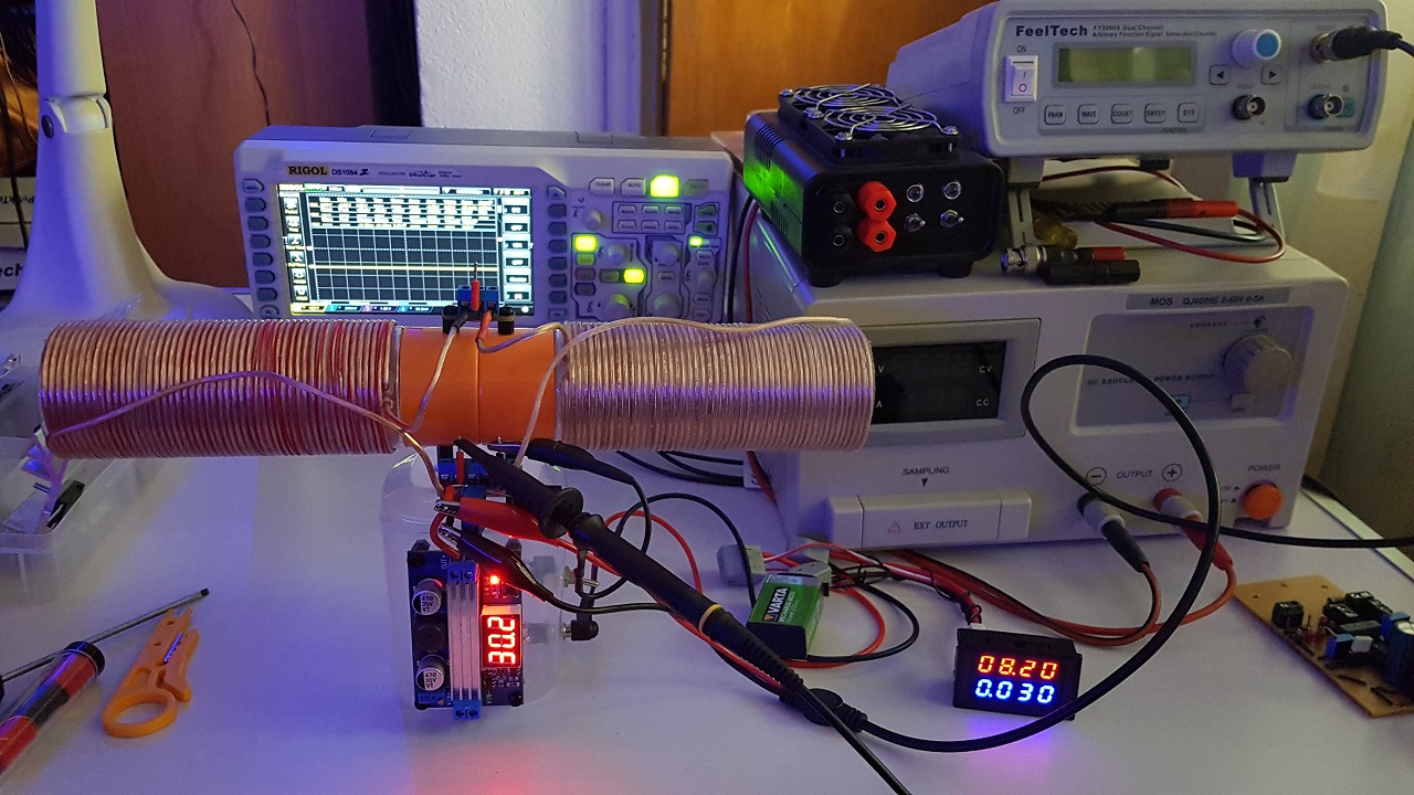
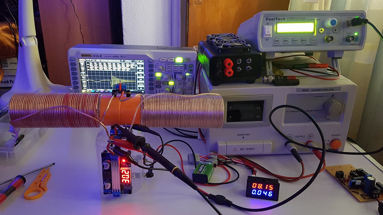
Last weekend I found some time to start work on building this experimental device.

I can't use 3D printing for this (too time consuming and probably expensive to design and print) so I need to use objects already available and adapt them.

I have about 10-15 identical plastic bottles I gathered for this and I can use them for building a modular device with interchangable parts.

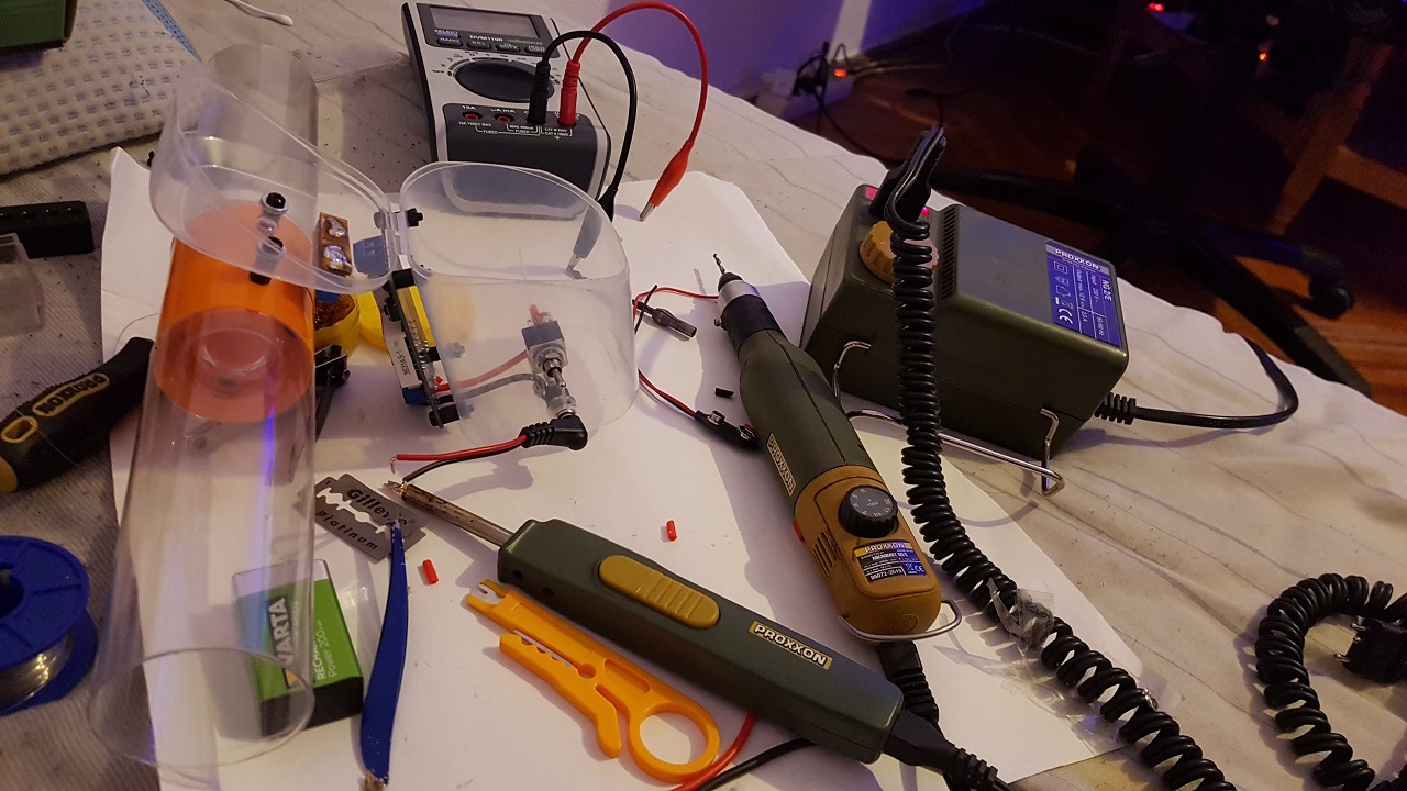
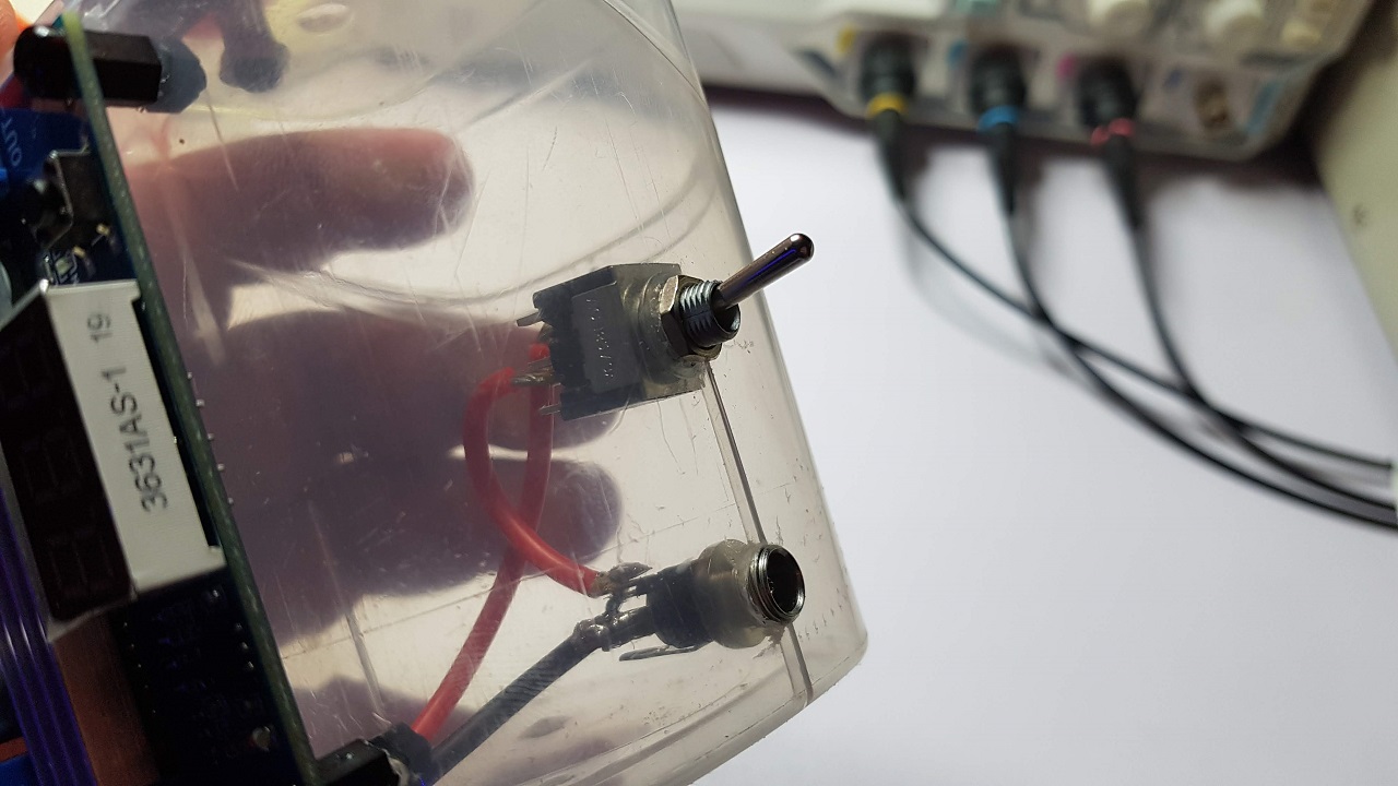
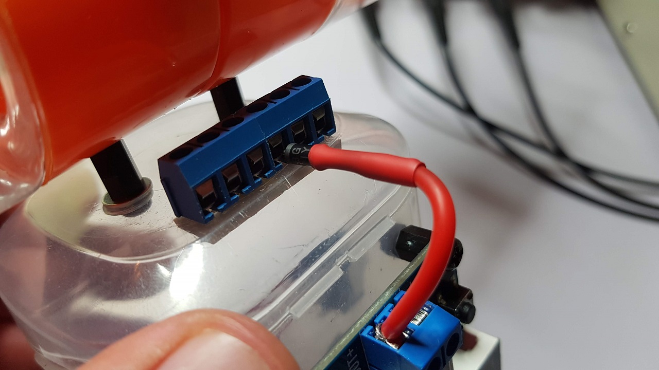
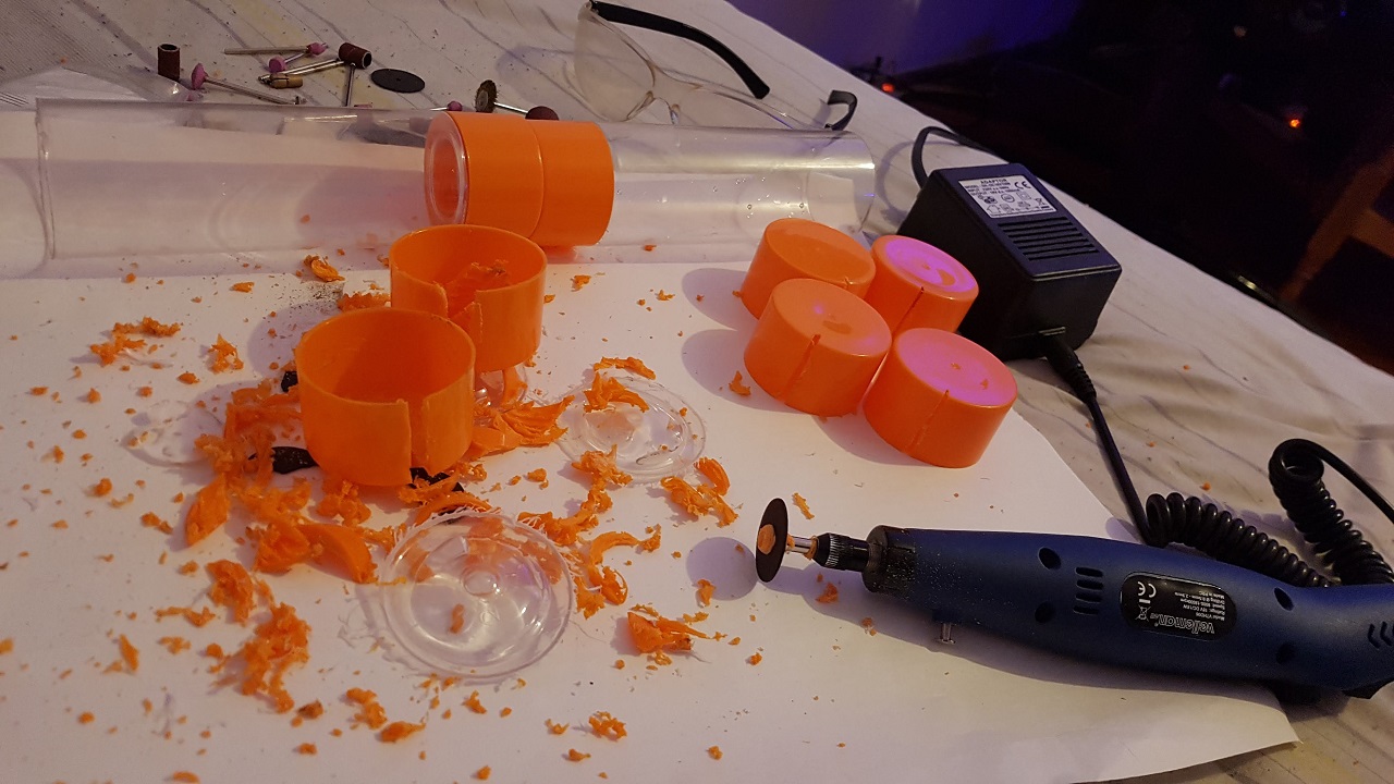
There was some work to do (and a lot of mess):

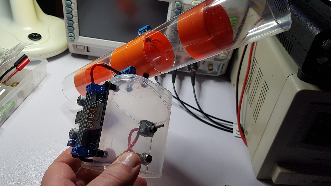
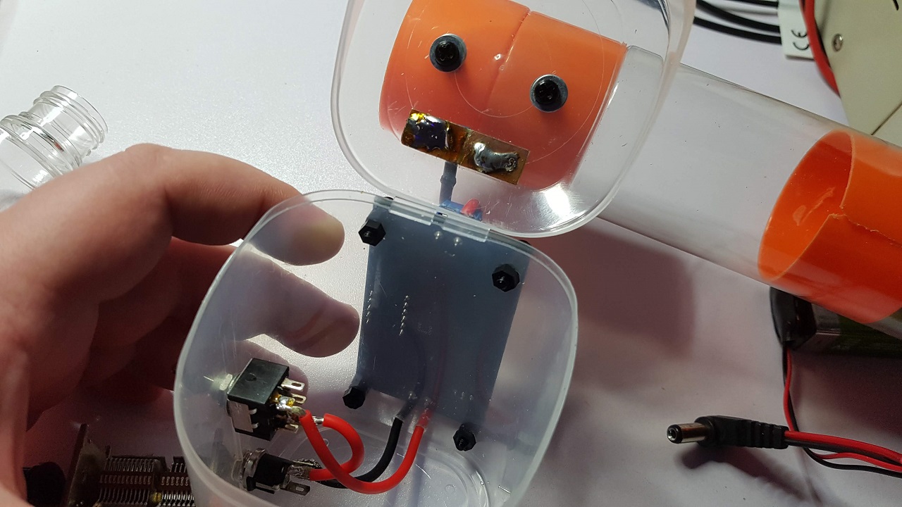
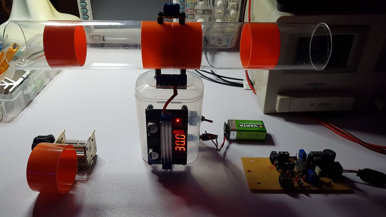
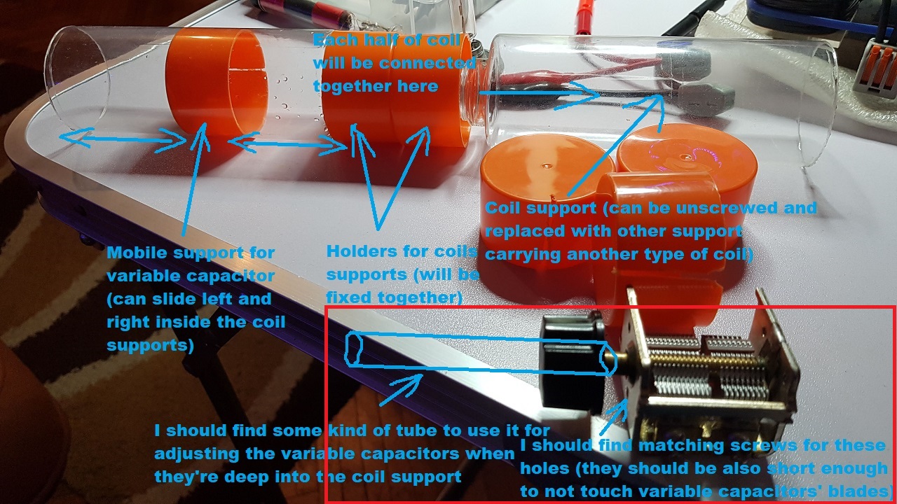
This is how I designed it in my mind before starting to build it:

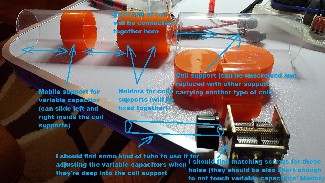
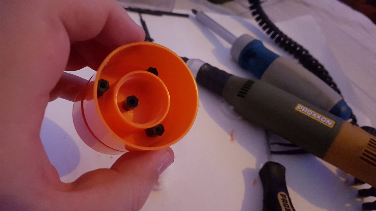
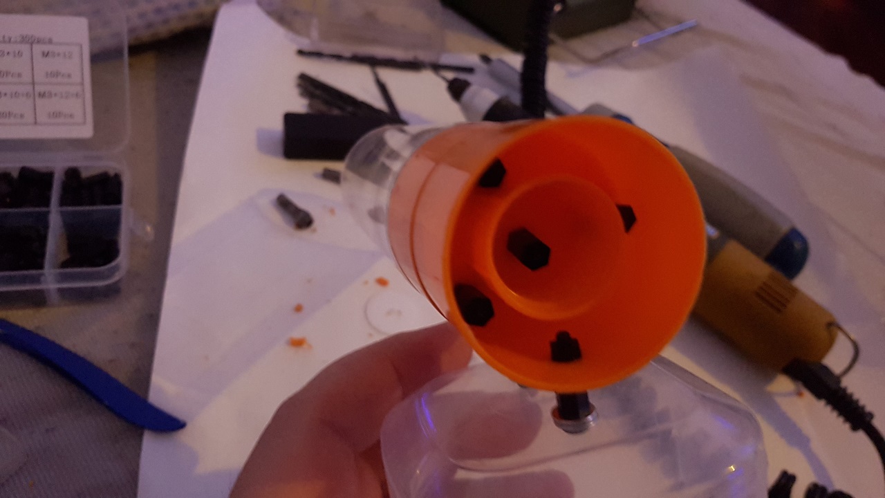
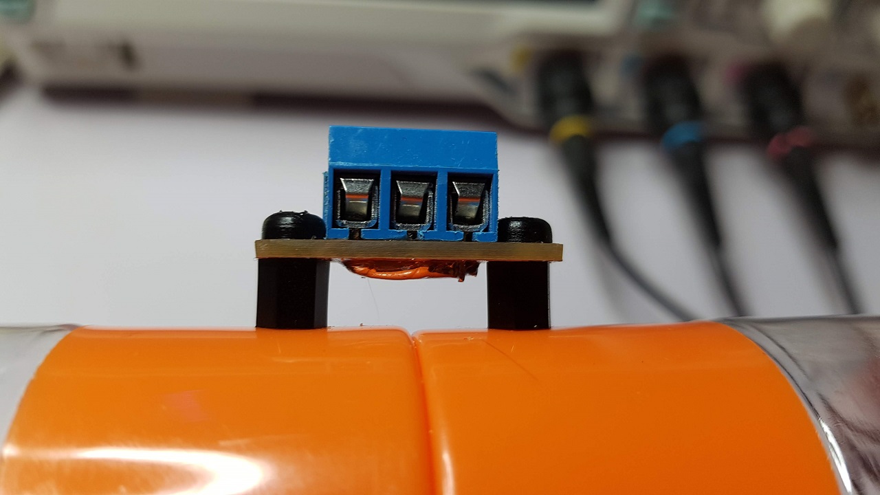
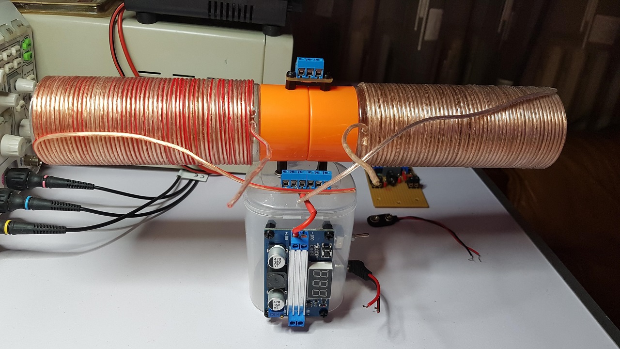
The caps in the middle will be fixed to each other and they will keep together the coils supports (the transparent tubes).

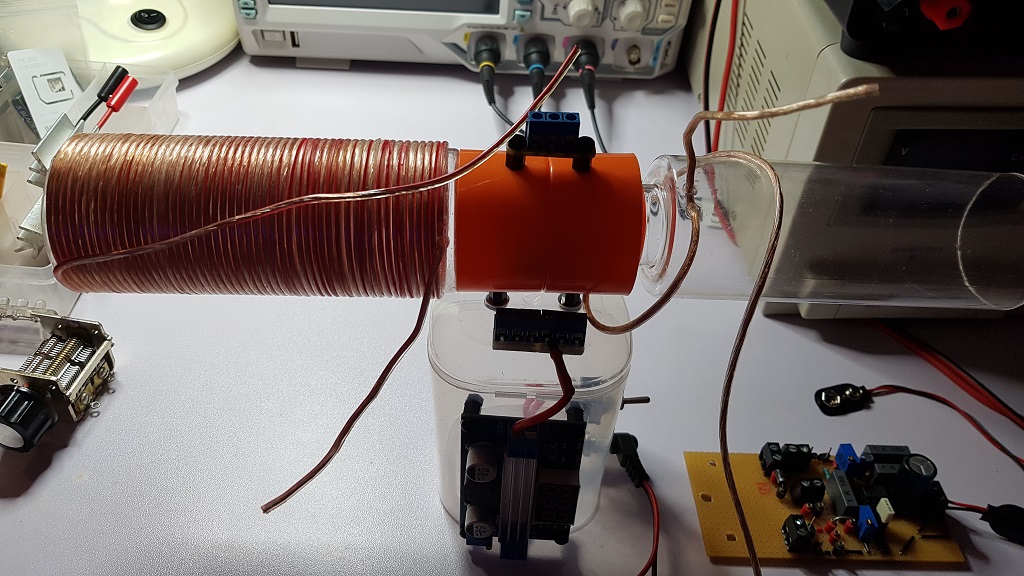
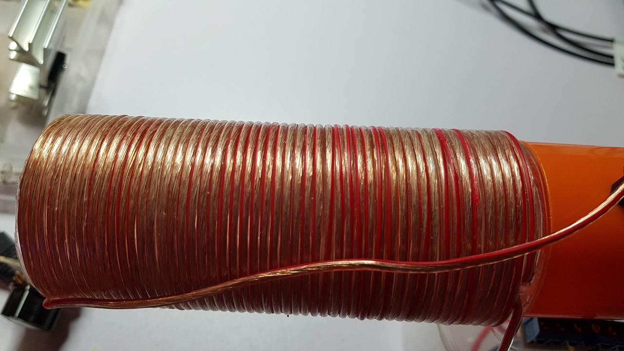
The coil supports are detachable (can be unscrewed) so I can easily wind the wire on them and then attach them back.

I can build more of these with different types of coils (single wire, bifilar etc.) as I need them without needing to unwind a coil and then wind a different type of coil again and again.

For example if at some point I want to have opposing coils I'll just unscrew the coil support on the right side and mount back another coil support having a coil opposing to the coil on the left side.

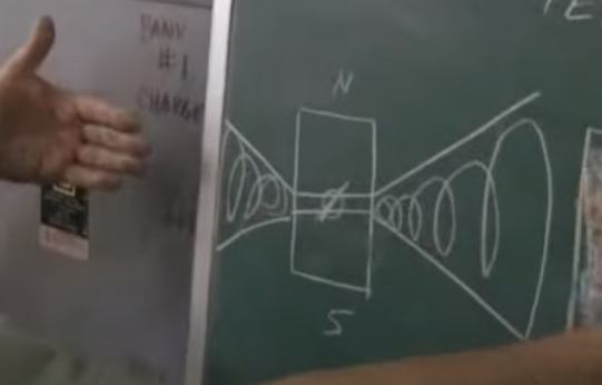
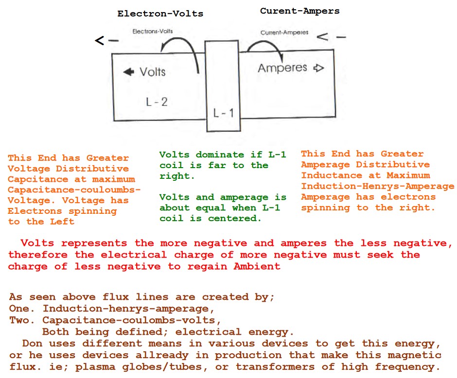
Why would I want that configuration ? Well, because as I said this should be a modular multi-purpose experimental device and at some point I intend to test this (as it appears in Don Smith's book) with a ground connection:

We need to test all the posibilities from what Don Smith told us.

Now back to the description of the device...

The variable capacitor supports are cut in a way that they are able to enter inside the transparent coil supports and they can slide inside so the variable capacitor can be placed at different depths inside the coils.

This is necessary for placing the variable capacitors in different zones inside the coils to see if there are any differences in the energy collected.

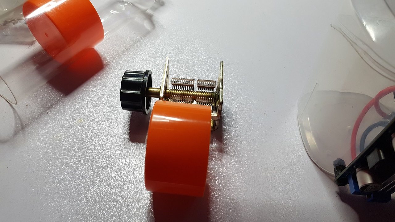
For now I need to find some kind of tubes to attach them on the variable capacitors trimmers so I can adjust them from outside even when they are slided deep inside the coils. I don't have those tubes yet and I need to find where I can find something like that or how to build them.

Also I checked and I don't have matching screws for the holes of the variable capacitors so I can fix them on their sliding supports. I'll search for that kind of screws. The screws lengths are important too, they shouldn't be so long else they will touch the variable capacitor's blades inside.

I still have work to do until the device is ready, I'll continue as I find time and I'll post updates here.

Regards,

Fighter

"If you want to find the secrets of the universe, think in terms of energy, frequency and vibration."
Nikola Tesla
Fighter posted this 18 August 2023

Hello,

Unfortunately this project is advancing slowly because I didn't found enough time to work on it.

Now I'm preparing to leave Bucharest until the begining of September so I'll not be able to work on it but I used the time I had until I live to advance as much as possible.

The device is starting to look like I designed it in my mind.

I'm adding some photos and details.

I assembled the piece which will keep together the coil supports:

Sorry for the mess...

I added inside the device a power jack, a switch and soldered the wires to them:

I soldered two connectors to a board placed inside the device, will be useful for connecting the power wires to the coils and will have an extra slot for free for each connector. The 3 slots on the left side are connected together and the other 3 slots on the right side are connected together.

In the image above you may notice a red wire having a fast diode, that wire is the positive coming from a 30V (that's adjustable) DC-DC voltage booster. The diode is there to stop the BEMF from coils to reach the output of the voltage booster.

On the top of the piece which keeps together the coil supports (the transparent tubes) I placed another connector which will be useful for connecting together the left coil with the right coil. Or halves of coil, depends on the experiment's configuration, that's why I've built the device modular with changeable coils - to be used in diverse experiments/configurations specific to Don Smith's technologies.

In the next photo you may see some details inside of the device (the electric circuitry).

And this is the current status of the device's construction.

The device will be powered by a rechargeable 9V battery.

Between the battery and the device I will use a digital DC power meter like this to observe the input power.

The voltage booster will rise the voltage to 30V (that's adjustable).

On the output of the voltage booster, on the negative I will place a MOSFET which will be driven by my replica of Jagau's Square Wave Oscillator or sometimes maybe by my signal generator.

I'll continue to work on the device when I'll return, I still need to mount the variable capacitors on their sliding supports.

After that I'll need to build the coils and then finally start the experiments.

I'll keep posting updates here.

Regards,

Fighter

"If you want to find the secrets of the universe, think in terms of energy, frequency and vibration."
Nikola Tesla
Jagau posted this 30 May 2023

A Don Smith tribute in pdf

Jagau

“Energy cannot be created or destroyed, energy can only be transformed or converted”


Attached Files

Shelfordella posted this 08 July 2023

This recent video of Master Ivo has too much resemblance to Don's Tesla POC, maybe it contains an idea or two for your experiment:

"A little theory and calculation would have saved Edison 90 per cent of the labor." Nikola Tesla

Jagau posted this 08 September 2023

 Hi everyone
Listened to John Bedini explaining on the board where the Energy of the universe comes from 15.08 until 17 min    Very interesting

https://www.youtube.com/watch?v=wprK-cwXLig&t=908

Don Smith often speaks of bloch wall, look at double cones and how he explain it, dont forget Bedini is a electronics engineer

Energy comes this way

 Jagau

Fighter posted this 18 September 2023

This weekend I've got some available time so I've built the two halves of the coil:

I needed to take precise measurements to make sure the two halves of the coil are (as much as possible) identical so they have identical natural resonance frequency.

That will be very useful later as I'll use them in multiple scenarios as Don Smith shown to us.

Keep in mind they're part of the same coil (no opposing magnetic fields) and their winding is the same: CW (clockwise).

As it's very late here and tomorrow I have work I'll comeback with more details about their construction, specs and of course measurements (resistance, capacitance and resonance frequency).

Hopefully these measurements will show identical numbers or as close as possible (considering the fact that I've done the windings manually).

We'll see...

Regards,

Fighter

"If you want to find the secrets of the universe, think in terms of energy, frequency and vibration."
Nikola Tesla
Fighter posted this 21 September 2023

Found some time to make coils measurements and organize the information for posting it here.

So here are the details.

I used the wires from an  2 x 0.75 mm2, 20 meters length speaker cable I bought from here.

This is the label of this type of cable showing more details:

I splitted the two wires of the cable then I temporary wired a coil on one of the transparent coil supports to measure how many turns a half of the coil could have considering the length of one of the coil supports.

Turned out that each half of coil should have exactly 8.75 meters and 50 turns. So these are the physical specs of the two halves of the coil.

I've made the measurements with my LCR meter for: left half of the coil, right half of the coil and the full coil.

As the photos of the measurements are too many I'm not gonna post them here but I'm attaching a archive to this post containing the original high resolution photos.

Here I'm gonna post summaries of the readings from my LCR meter (set to make measurements at 200 KHz). 

So here they are.

  • For the left half of the coil:

  • For the right half of the coil:

  • For the full coil:

So we have:

  • Left half of the coil: wire length 8.75 m, inductance 43.62 µH, capacitance 14.53 nF, resistance 0.60 Ω;
  • Right half of the coil: wire length 8.75 m, inductance 42.98 µH, capacitance 14.82 nF, resistance 0.60 Ω;
  • Full coil: wire length 17.50 m, inductance 86.92 µH, capacitance 7.289 nF, resistance 1.22 Ω.

As the measurements are showing physically and electrically the two halves of the coil are almost identical (considering the fact that I've built them manually) so their natural resonance frequency should be the the same just the way I intended.

When I'll find time I'll set up the testing experiment in order to find their natural resonance frequency and I'll post the details here.

For now I just added this info here, it will be very useful later during the coming experiments.

Regards,

Fighter

"If you want to find the secrets of the universe, think in terms of energy, frequency and vibration."
Nikola Tesla

Attached Files

Jagau posted this 31 October 2023

I understood, 10 KOhm resistor between MOSFET's ground and gate. Should it be a power resistor, like 0.25 W or maybe more ?

On a mosfet you can put a low power resistor, 1/4 watt is ok, there is no power on a mosfet gate, only voltage threshold must be respected and no more threshold voltage for your mosfet spec. If you leave the gate floating the mosfet will conduct almost all the time by adding resistance it will discharge, you should never leave a gate floating.

For the booster, it is the DTC of the mosfet which will create the current demand, the DTC is very important. With a cap of 1000 uf it is sufficient and it will help the booster for instantaneous demand.

To avoid heating the Mosfet you will have to find a way to direct the BEMF towards a circuit for recovering this voltage produced by the coil when the Mosfet closes. Most mosfets burn because of this.

There are several good YTs on this subject.

Jagau


Fighter posted this 04 December 2023

Hello,

I tested the device with the coil connected and the switching module is working as expected now, the signal is clear (no distortions):

As seen in the video, based on the check I've made with my Field Tester there seems to be a significant amount of energy available inside the coil.

For now the device is starting to look and behave like what I saw in Don Smith's experiments: I see about 500Vpp (point-to-point) for just 1% duty-cycle and a lot of ringing of the coil for a while after the MOSFET is turned off. 

It's a good first step.

The MOSFET is a just a bit warm, for now I don't think it requires a radiator.

This image contains the scope readings and the signal generator parameters as seen in the video above:

And this image is showing the consumption of just the voltage booster alone (with the MOSFET turned off, see the signal generator turned off):

While playing with the device I noticed I can decrease the input very much (from ~140mA to just ~46mA) by decreasing the AMP parameter on the signal generator from 12V to 8V and we still have ~390Vpp in the coil which is very good:

Let's keep in mind that the consumption of the voltage booster alone is 30mA so we'll getting these ~390Vpp in the coil with just ~16mA.

Another way to decrease the consumption is to increase the frequency but that will result in proportionally decreasing the Vpp in the coil.

Now the remaining question is if the input is affected or not when we extract that energy we see in the video around the coil and especially inside the coil.

I need to start building the extraction module: the variable capacitors fixed on their mobile supports, wires connected to them, some tubes connected to their axis so I can rotate their axis from outside while they're placed deep inside the coil, more specific this (as seen in the red rectangle):

These parts of the device are still pending, I'll try to find time to build them and I'll post updates here when they're ready.

Regards,

Fighter

"If you want to find the secrets of the universe, think in terms of energy, frequency and vibration."
Nikola Tesla
Fighter posted this 16 January 2024

Here is a video about how the ground connection can amplify the energy of a device by being in resonance with Earth:


Regards,

Fighter

"If you want to find the secrets of the universe, think in terms of energy, frequency and vibration."
Nikola Tesla
Close