BTG research

  • 5.1K Views
  • Last Post 07 January 2023
Vidura posted this 03 August 2022

Hello Friends, I will import this thread; from the backup forum to the public category ,it is dedicated to the BTG devices like the ones shown by Ruslan and Akula. The Goal is to gain knowledge about the involved principals, and hopefully to achieve a working, self-feeding machine. Regarding the tier2 category , I want you to know that I was really tented to post for general public, and certainly the thread will be moved in the replications category when the time is right. But I also know that various persons got in serious troubles , and likely a young man lost his live, because this is the kind of devices produced in series would sensibly cut in the profits of the big energy companies.

We will in a first step go in diakoptik manner thru the different parts of the device and make different kinds of experiments and tests to get basic understanding of how this devices are working, and the interaction of the different parts. Also we will collect information from various sources from the original Builders. I would encourage those of you , who are interested in following or participating in this project, to read the thread about longitudinal waves , as this describes one of the  basic physical principals involved in this device.

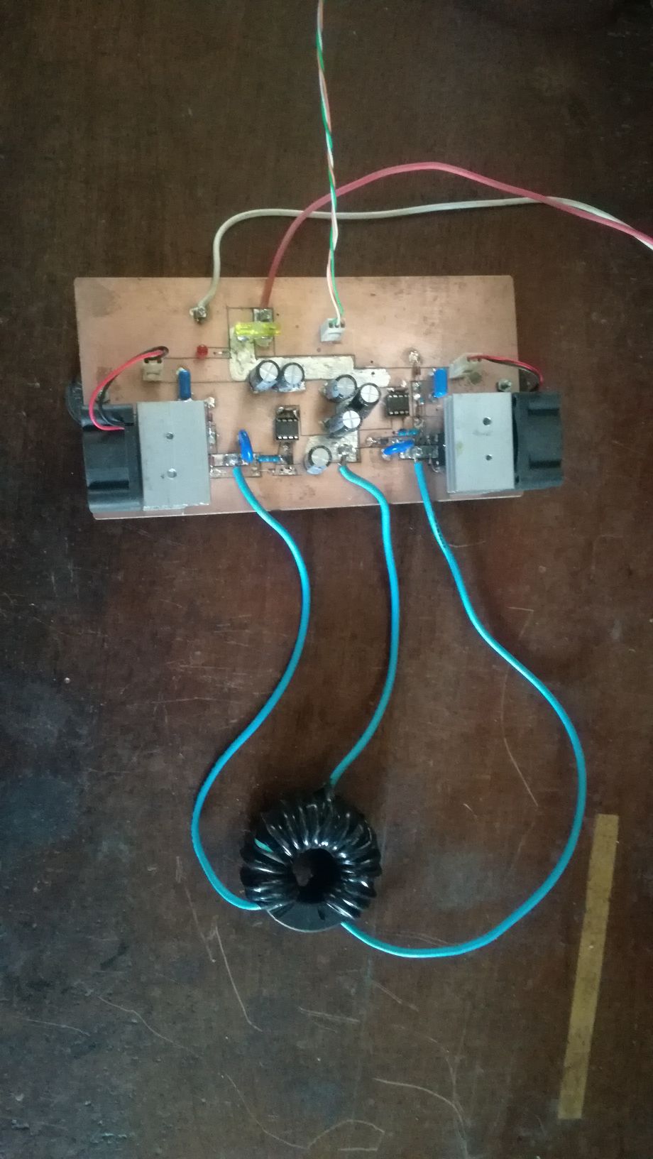
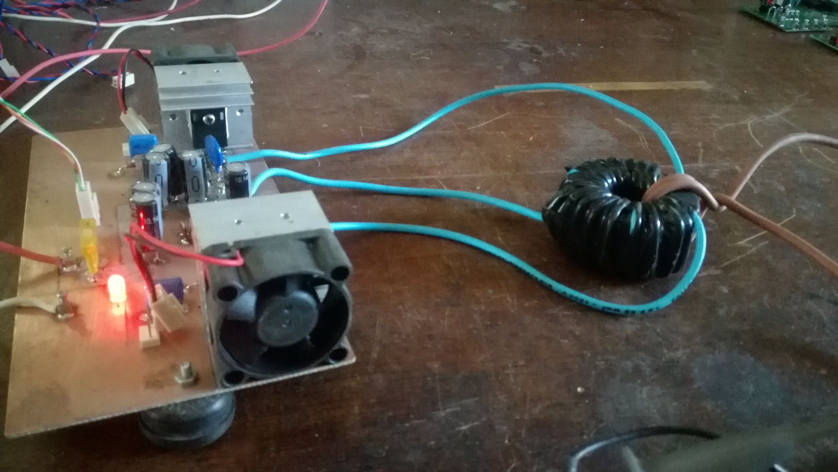
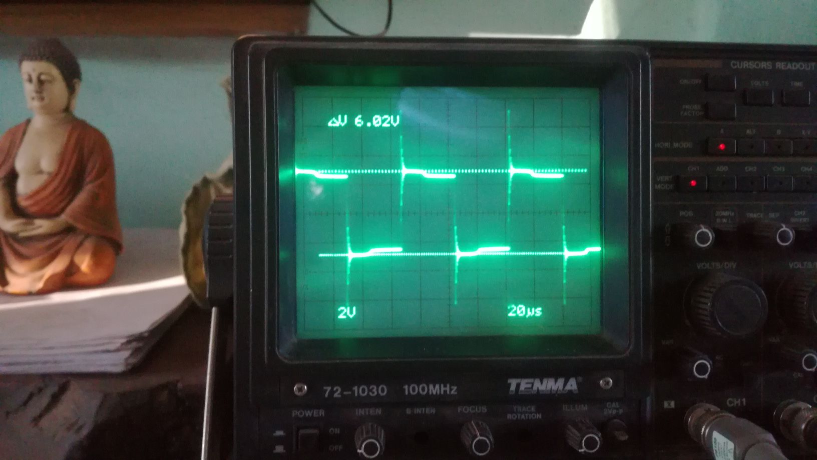
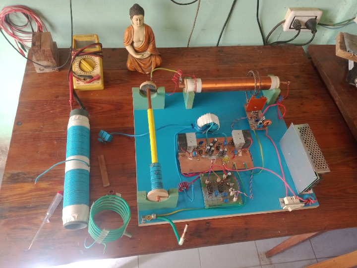
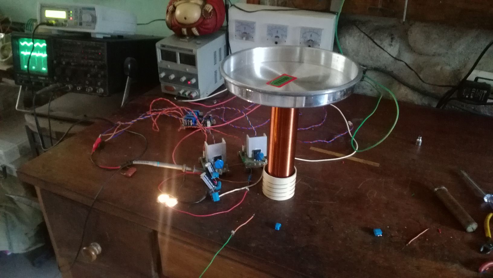
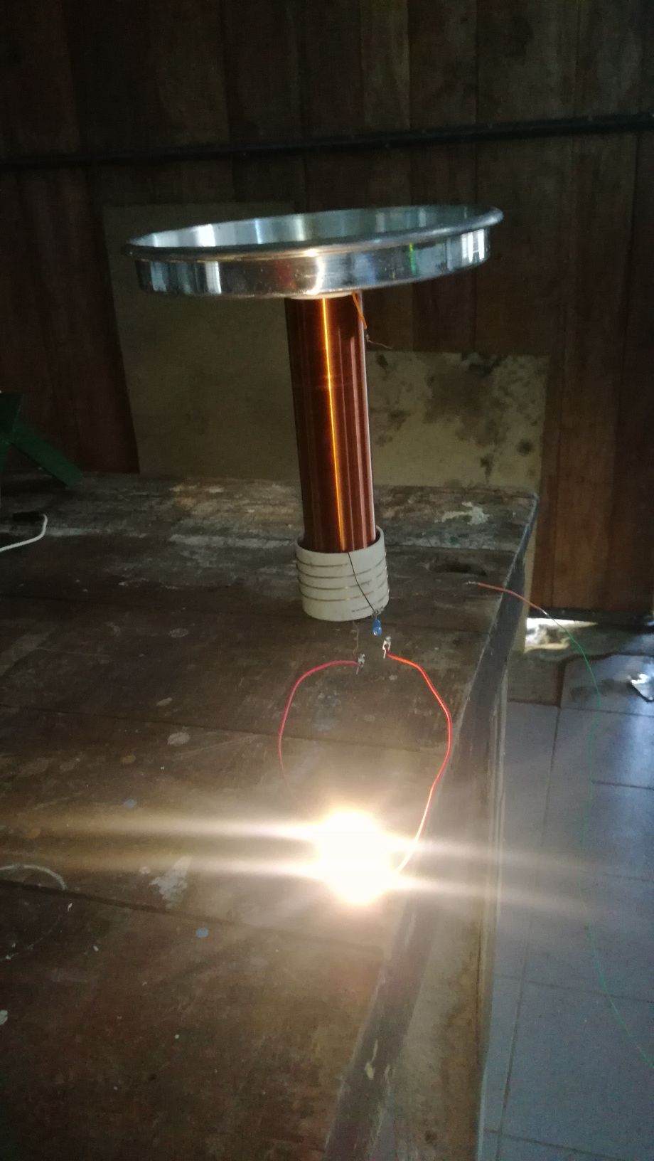
The First Part of the device we will cover is the push-pull converter. It's function is pumping charges, an analogy would be the electron-gun in the CRT, it is the source of charges. There is no magic in this part, it is just common EM technology, there are different topologies which could be used, half or full bridge would be suitable. For low frequency devices like the Kapagen also an of the shelf silicone steel transformer could be used. It is important that the output is AC. In the research we will stick to the push-pull topology for the ease of switching the two low side IGBT's. Here some images from testing this stage:

As I have time ,Ill continue to upload content and updates or corrections.

Vidura

Order By: Standard | Newest | Votes
Vidura posted this 03 August 2022

Hello Friends, I will import this thread; from the backup forum to the public category ,it is dedicated to the BTG devices like the ones shown by Ruslan and Akula. The Goal is to gain knowledge about the involved principals, and hopefully to achieve a working, self-feeding machine. Regarding the tier2 category , I want you to know that I was really tented to post for general public, and certainly the thread will be moved in the replications category when the time is right. But I also know that various persons got in serious troubles , and likely a young man lost his live, because this is the kind of devices produced in series would sensibly cut in the profits of the big energy companies.

We will in a first step go in diakoptik manner thru the different parts of the device and make different kinds of experiments and tests to get basic understanding of how this devices are working, and the interaction of the different parts. Also we will collect information from various sources from the original Builders. I would encourage those of you , who are interested in following or participating in this project, to read the thread about longitudinal waves , as this describes one of the  basic physical principals involved in this device.

The First Part of the device we will cover is the push-pull converter. It's function is pumping charges, an analogy would be the electron-gun in the CRT, it is the source of charges. There is no magic in this part, it is just common EM technology, there are different topologies which could be used, half or full bridge would be suitable. For low frequency devices like the Kapagen also an of the shelf silicone steel transformer could be used. It is important that the output is AC. In the research we will stick to the push-pull topology for the ease of switching the two low side IGBT's. Here some images from testing this stage:

As I have time ,Ill continue to upload content and updates or corrections.

Vidura
Vidura posted this 27 December 2022

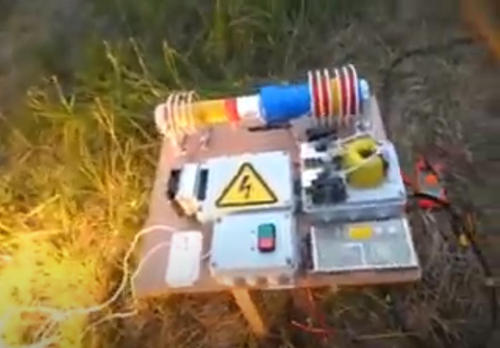
First I want to make clear that whenever possible I adhere at classic physics, which IMO can satisfactory explain over 90% of all observed phenomena. But not all. On the observations of the mentioned effects I will remark the following : 1. The phase shift between the two scope traces. If we consider the effect as produced by Coulomb forces, the influence on the unconnected scope probe should be bthe same as exerted on the reception coil. But there is clearly a difference of 90° compared wit the bifilare cancelling Coil. 2. The assimetry of the positive and the negative halfwaves.There is around 5 volts of difference in the potential, so it seems that the coupling is prevalent on one polarity, positiy on the terminal of the bifilare section. 3. The long time interval until reaching the maximum amplitude. It lasts around 5-7 second's until reaching the maximum. I have observed that there is a kind of storage of energy related to this effect. When the experiment is repeated several times, the pattern change and the first time interval of powering up becomes faster. When de device is powered on for first time after a longer period of staying unconnected, it is much slower and clearer to observe. See in the short addition below:

Vidura

Vidura posted this 22 December 2022

Hi all.
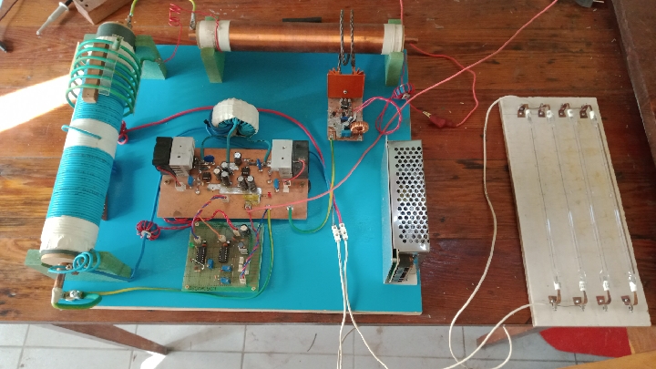
Update: In order to make a series of tests to learn about the interaction of the two resonators, I have built this board. It allows an easy exchange of components and coils, while maintaining an ordinated layout.

As stated before, I am very busy this time of the year. Additionally I had  a lot  of offline time lately, due to a server problem. But finally, I could do some tests.

Here you can see the parts inside the main rwesonator. Still I did not get the expected results, when the HF pulses are activated ,the amplitude of the mainresonator decreases instead of increasing. regardless of the timing of the signal. So I guess there is some issue with the feedback, but with patience and persistence it will be solved. As time allows I will continue and troubleshooting why the increase of the oscillations is not present.

Vidura

Vidura posted this 26 December 2022

Here a video showing some interesting effects:

Vidura

Munny posted this 24 December 2022

Have a look at Ivo's setup.  I helped him years ago get to this point and he's got stuff now worth incorporating into your project.

If you want to switch even faster there are components known as cascodes and they can be created using a MOSFET combined with a JFET.

Ivo much prefers pancake coils over cylindrical coils which you might want to consider.  They have their pros and cons like any other engineering solution.

Vidura posted this 03 August 2022

There are missing some posts of other members from the original thread on the AU forum. below a serie of videos from the experiments related to the research:

the playlist of videos 2-9 :

https://www.youtube.com/playlist?list=PLbhv9RvImM8z4rsOpyOK0vSbgR49WGndK


Vidura

Vidura posted this 03 August 2022

Jan 30, 2021 at 7:52am Fighter, YoElMiCrO, and  4 more  like this
Quote Edit   
 
Post by vidura on Jan 30, 2021 at 7:52am
Hello all following: I will repost some parts of the thread which I think are useful.
  Here I will post some details of my Kacher circuit, but first I want you make aware of some safety and health considerations.
The Kacher coil, when properly built, can be a very powerful device. In some occasions, when I accidentally touched the hot area of the coil-antenna system, I received immediately strong RF burnings on the skin, leaving white burned strains on the smoking fingers. Also metallic objects close to the device can become electrified. Also the radiation of the Intense E-field have caused me headaches after a few minutes next to the running device. According Russian researches a prolonged exposure can lead to micro clusters in the blood, and cause thrombosis. So , If you decide to experiment with this device, you do it on your own risk, and should consider the recommendations to avoid burnings, and limit the time of the experiments to a few minutes, maintaining distance if at all possible. Take specially care if you rise the voltage and power rates, when using power transistors to drive the coil.
After having stated this , let's come to the details:
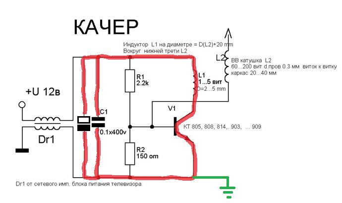
The basic Kacher-Brovin circuit for the E-field generation is as the one posted by Lostfox:

The traces highlighted in red have to be as short and thick as possible, the capacitors mounted close to the switch and primary. The earth ground connection close to the emitter of the transistor. The Primary coil should be wound with thick wire >6mm2, and a loose coupling to the secondary. Normally a few turns is sufficient. The transistor should be High frequency, with a good Amp. Rating and low hfe factor. From what I had at hands, the 13007 worked best. For higher power ratings I joined three units in parallel, with a good heatsink.

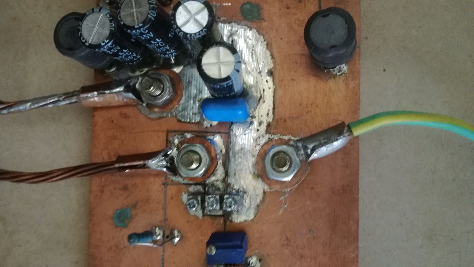
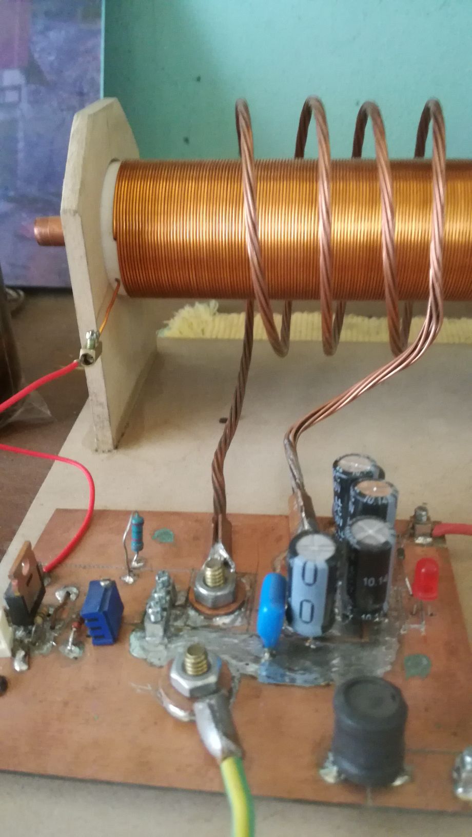
In my circuit I use a adjustable R2, the base voltage should be adjusted to slightly above 0.5V. In My unit I also mounted a modulation switch, this allows to perform amplitude modulation by tying the base to ground periodically. Below some detailed images from my circuit:


Vidura

Vidura posted this 03 August 2022

Jan 30, 2021 at 10:58am Fighter, YoElMiCrO, and  3 more  like this
Quote Edit   
 
Post by vidura on Jan 30, 2021 at 10:58am
Here I recovered the video links from the old scientist, which have been posted by Lostfox:

Below some images of my replication of scalar energy transfer:


Vidura

Vidura posted this 08 August 2022

In the above post I attached a link for the file in which the experiment and its underlying principles are described. In this context it becomes clear that replacing the static (DC)charge of the plastic ruler by a longitudinal resonator the antinodes change the polarity with the resonant frequency(AC). This is the reason why the energy extraction requires a synchronized switching to avoid dampening of the resonator. The cycle when the potential is rising and pulling charges from the ground has not to be disturbed, only when the potential is falling the excess charges should be dumped into a capacitor or load. And regarding the coulomb forces, as only negative charges are able to move in a solid conductor, it might be convenient to make use only of a quarter of the period(only one polarity) for charge extraction. The Idea is to get work from the attracting force between unlike charges, without a dampening effect on the resonator caused by repelling of like charges in the cycle of falling potential.


The second method of energy collection from a resonator is quite different, as it is not based on the action of coulomb forces. In the thread about the "concepts of AU devices" I made an introduction on the physical principal of this method, which has analogies with the heat pump. The most BTG devices published on the internet are based on this second method. In the before mentioned thread we have extensively covered the topic of excitement and ionisation of atoms, from the Frank-Hertz experiment, the principal of the laser and the specific energy quanta for different elements and/or electron shells. The essence is that an atom of a specific element can be excited only by a matching amount of energy(for example a specific potential of EMF, or a photon of a specific wavelength). If the amount of energy is greater or less, the atom is not capable to absorb it, and rise the electrons to higher orbitals.  Therefore it is required to feed precisely calibrated pulses to this devices, beside the matching frequency for the resonator.

Vidura

Itsu posted this 22 November 2022

Vidura,

thanks, so when you say "Regarding the HF pulses, lately I believe that rectification is not needed," do you mean that you have come back from your (2nd part) statement in the linked post where you say:
"There are at least two conditions necesary to get: the modulation of the HV wave has to be in phase with the lower frequency oscillation, and very important, only one polarity of the former 
have to be applied".

I mean your "only one polarity of the former have to be applied" statement.

So the AC coming from the kacher (say 1.2MHz) is OK to use but only when in phase with the second quadrant of the period of the push pull frequency (say 24kHz)?

Thanks,  Itsu 

Itsu posted this 24 November 2022

I missed the video playlist from Vidura in his 2nd post here: https://www.beyondunity.org/thread/btg-research/?p=&order=all#comment-0012ef69-8926-4d22-80a0-aee6006bc8c2

This playlist to be found here: https://www.youtube.com/playlist?list=PLbhv9RvImM8z4rsOpyOK0vSbgR49WGndK contains a list of videos concerning the BTG including the kacher, push pull, antenna, Grenade etc. with valuable data and measurements.

Modulating (interupting) the kacher also is touched upon and showing the same problems i ran into (not able to get the kacher output sharply pulsed due to the ringing effect).

Thanks,   Itsu

Close