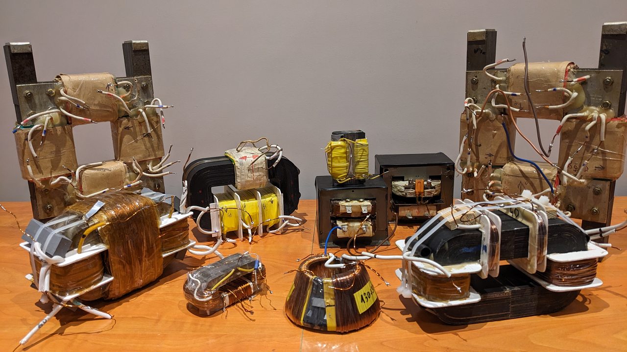
Atti's successful ZPM replication

  • 4.1K Views
  • Last Post 27 November 2023
  • Topic Is Solved
Atti posted this 25 November 2022

Hi everyone.

I just wanted to look at a few things in this simple compilation. As you can see, it's almost the same drawing as the one that Fighter gave us. I played with it a bit.
The core is a tiny Amcc20. Frequency between 90-110Khz. Filling factor 50%. Supply voltage between 20-30 volts. The power supply L-C filter works well. Roll ratio 1:2

Changes caused by parasitic capacitances are inevitable at such a high frequency. You can see them in the two videos. Sometimes the power is increased and sometimes the current is reduced.
Grounding can help in some cases. But the influencing factor must be taken into account during the measurements. It only has an effect above a certain frequency.
This is just for information, but as you can see, there are cases when the current drawn from the power supply is close to zero. There are times when grounding is necessary.

In this oscilloscope examination, I was curious as to where and how the two coils resonate. Or how I see it. Or is it visible at all.

When the current drawn from the power supply is the lowest, the CH2 (blue) channel is at a higher voltage. But this is the coil with less turns. Thus, it should be smaller by default (or at a lower frequency). So when this coil is at a higher voltage, it works on the other coil and charges back to the power supply. (here I deliberately did not say L1 or L2 because only the principle is the point, but this still awaits further investigation)
In some cases, the hump characteristic of parametric excitation can also be observed in the measured signal. Vidura alluded to this in one of his comments.
I have not done the loading according to Fighter or YoElMiCrO. The change is not so spectacular for the load.

It would definitely be necessary to use an iron core with a larger volume and a coil with a larger surface area.
This experiment was just for information on my part. To be continued later.

@Itsu.

As you can see, the current can be reduced to almost zero. Probably also with higher loads. The generator effect can prevail. But there are a lot of questions for me right now.

Atti.


realco posted this 22 January 2023

Hello Atti. No doubt as always. Congratulations

Unfortunately I had not seen this clip.

The_last_abc posted this 25 January 2023

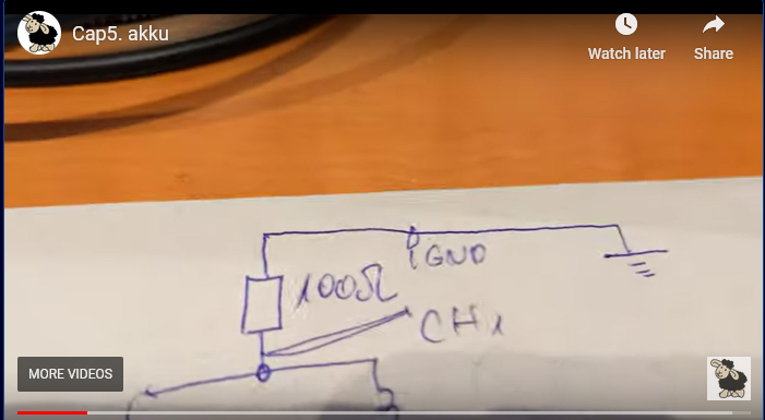
Can you replace the resistor in the picture with a 1K potentiometer?

Then replace the resistor with an ultra fast high voltage diode.


Quoting:Atti

Now I'm concentrating on confusion. Also, disturbance may not always be disturbance.

I have two types of laboratory power supplies. Don't worry about the fact that it's self-made. It works perfectly!
One has switching operation and the other is linear. I like to use the latter. (Although the external L-C filter does its job well.)

Each power supply has a toroidal transformer.

Unfortunately, this is precisely why capacity develops on the primary and secondary coils. (if we don't know what we're doing!)
The capacitance between two or more coils is formed due to the proximity or the windings on each other.
By the way, I checked this on other transformers and it is the same for all of them. However, the voltage transferred by the capacitance thus formed significantly affects the operation of the given device. If aparameters stand together!
But don't believe what I say. Check everyone.
Not only the voltage, but also the frequency carried by the voltage is transferred. Thus, a kind of FM modulation can occur. And this depends on several factors. You can hear the mosfet disturbance in the video:


Another problem could be the timing circuit. (i.e. opening and closing the mosfet gate)
  In some cases, this kind of connection problem may occur.
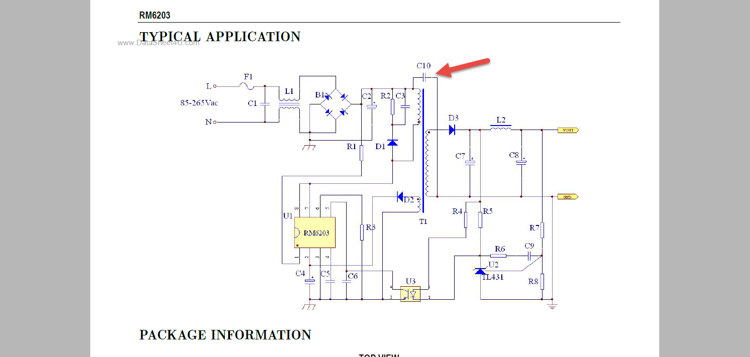
Coupling problems can also occur in switching mode power supplies or function generators. This can be caused by the installation of the so-called cooling Y condenser in some cases. This is also located in its internal power supply. (but not always!!!) It is mentioned in this forum. Image:

https://www.eevblog.com/forum/testgear/feeltech-fy3224s-24mhz-2-channel-dds-aw-function-signal-generator/225/

I also noticed that if the mosfet gate is not closed in time, it gets very hot.

Many people use this isolated drive and switch device.
Here they write about the problem, which can sometimes occur:

http://www.advanced-science.com/IPCQuadra.html


In some cases (in my case at frequencies above 150KHz) the mosfet gate may have a closing problem.
If the mosfet gate does not close in time, an excitation process may occur. Not in every case, but it can happen! Even with mosfet drivers!
  So. If the aforementioned capacity problem or the mosfet problem develops due to the power supply, we may be in for a surprise.
  Or even wrong information.


But let's not look at these problems. Let's just keep these in mind.
We know why we do what we do!

As we can see (although I have already shown), the grounding effect can also develop with batteries. Especially when it comes to high voltage.


This is why Vidura's work is interesting to me.
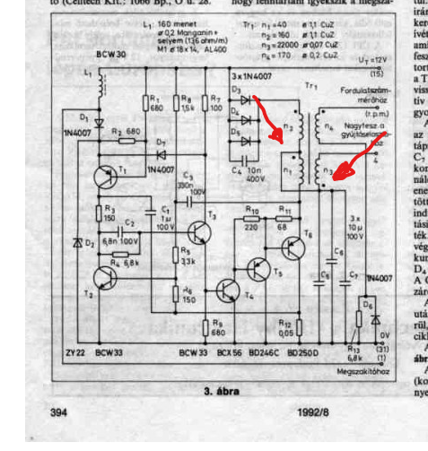
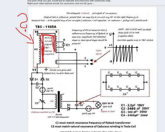
Notice the connection pattern of some inductances:


Atti posted this 26 November 2023

Pay attention to the details. Compare the operation of different machines.
What are the common points. 
Why the current decreases.
How does N. Tesla's transformer relate to the arrangements.
-ZPM
-Kapanadze
-Árpad Bóday
-Bulgarian M.E.G.
-T.Bearden's statement
-etcetera

What are the common points?


Jagau posted this 26 November 2023

One of the strengths of Tesla's strong arrangements was having a very loose coupling coefficient and Tesla's in particular had a way of changing inductance depending on how they were wound in order to switch to the top of the wave.


Perhaps Atti you can fill in what is missing?

Jagau

Atti posted this 27 November 2023

Hi,

Over time, I'll fill in what's missing.

Atti.

Close