Fighter's ZPM (Zero Point Module) failed replication by Itsu

  • 8.1K Views
  • Last Post 18 December 2022
Itsu posted this 07 November 2022

Hello all,

i opened this thread to discuss my replication of Fighter's ZPE (Zero Point Module).

I already opened a similar thread on OUR.com (https://www.overunityresearch.com/index.php?topic=4374.msg101654#msg101654 ), but will transfer some data from there to here.

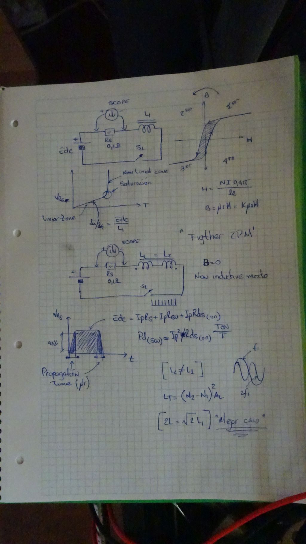
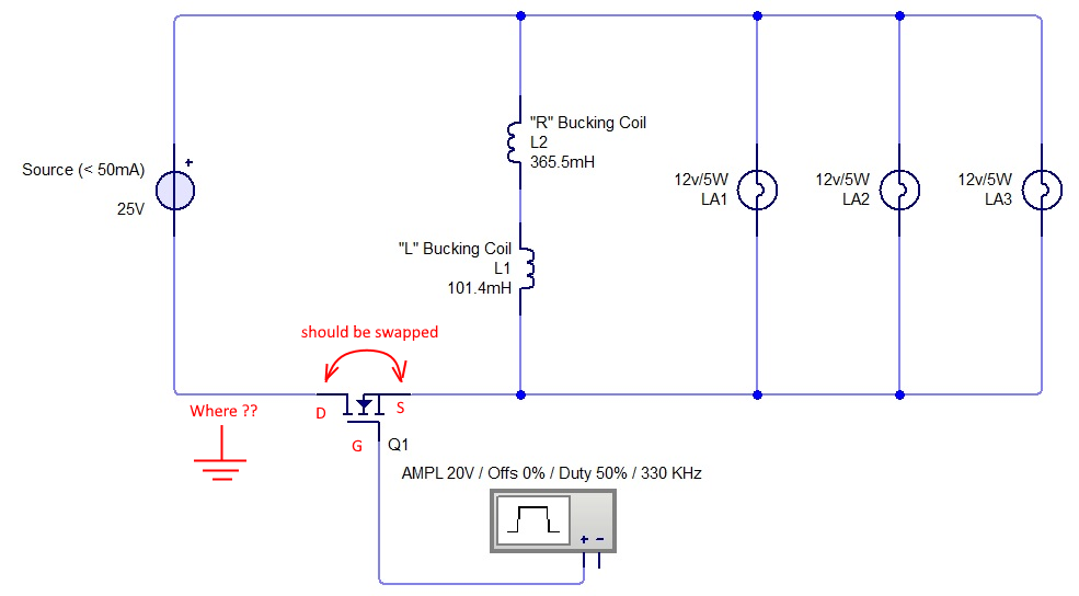
Initially i understood that the below diagram was correct and complete, but it turns out its not.
There is a ground connection somewhere, but i am not sure where it is exactly, hopefully someone can tell me.
The MOSFET is shown wrong as the Drain and Source should be swapped, which was corrected later in Fighter his thread so therefor the mentioning in red.

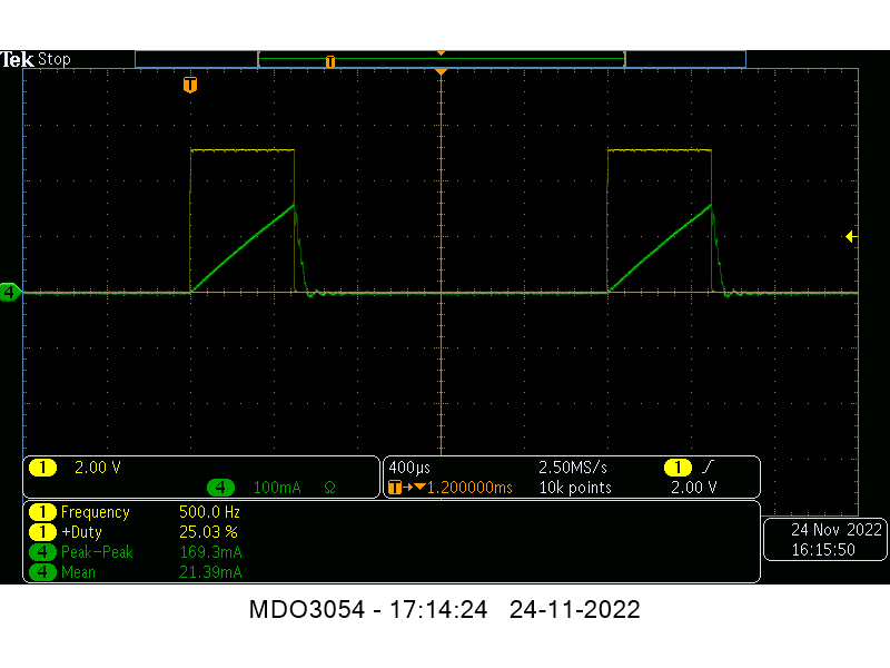
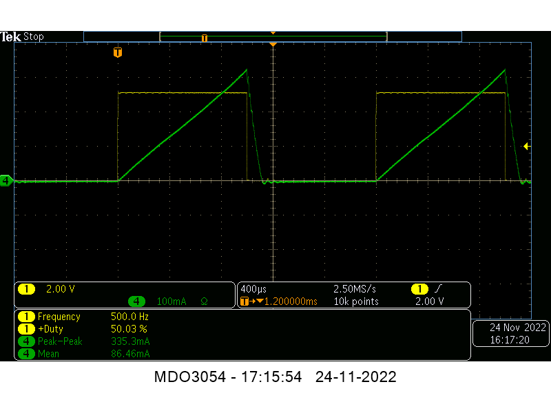
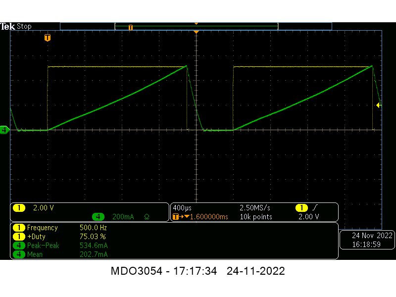
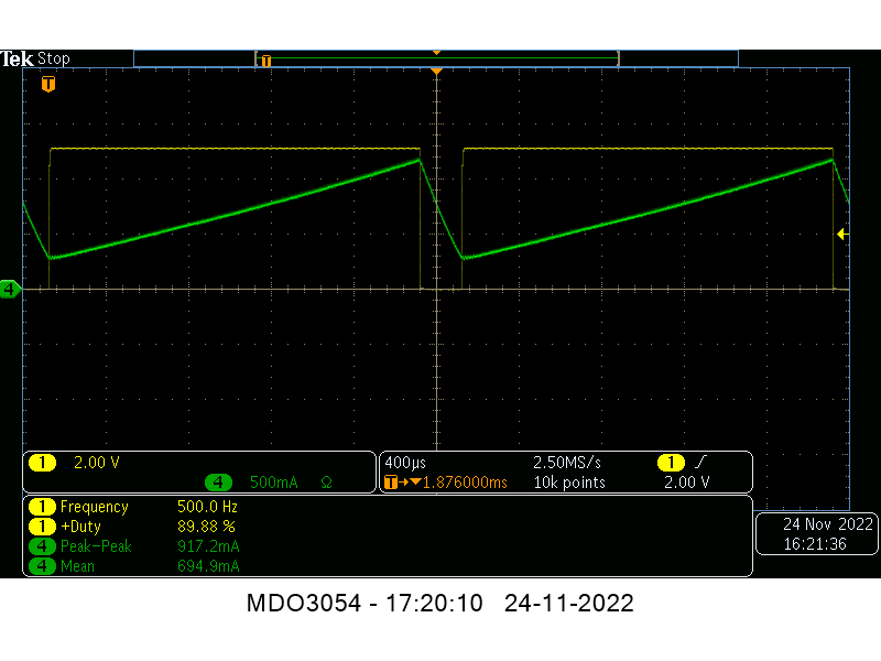
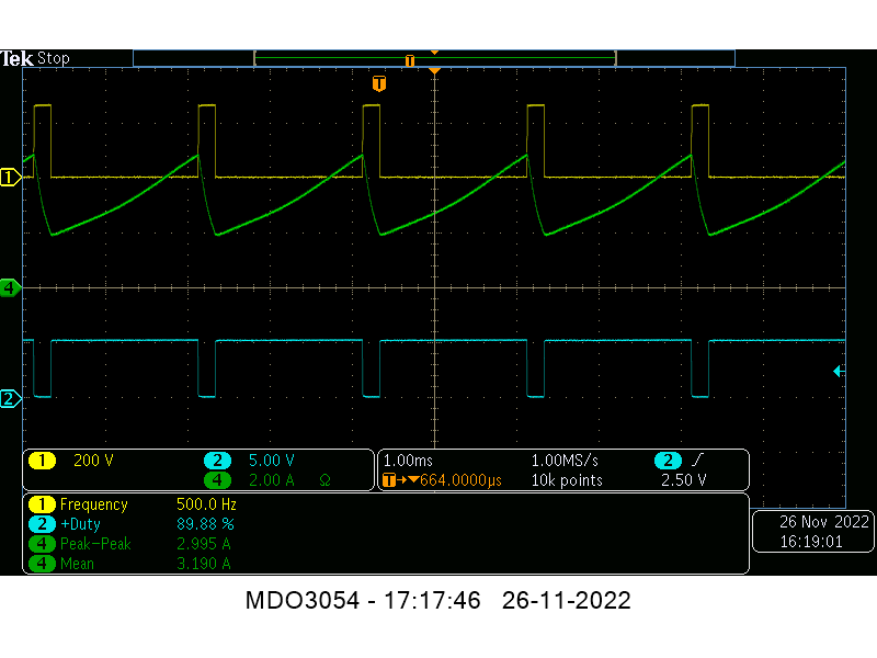
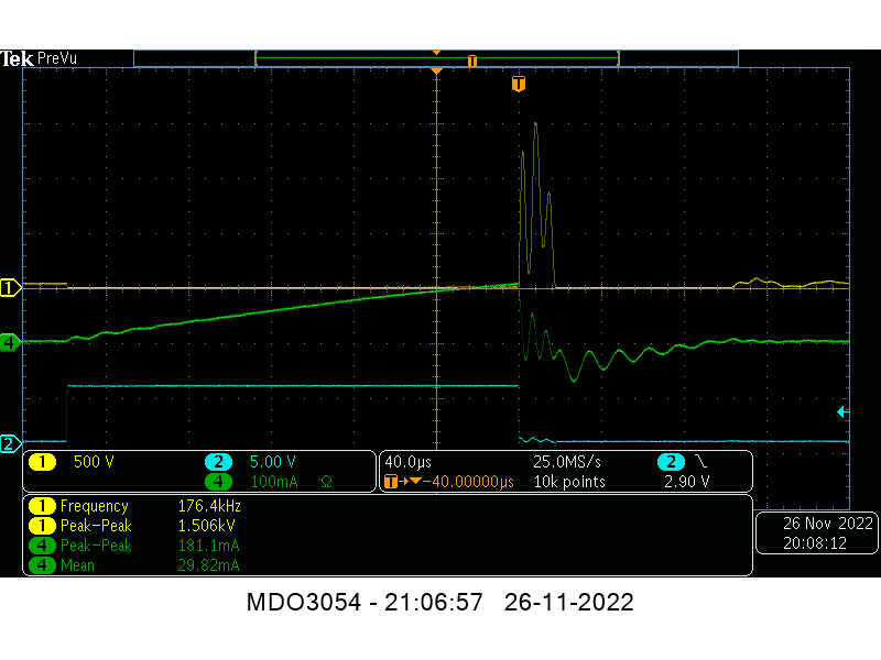
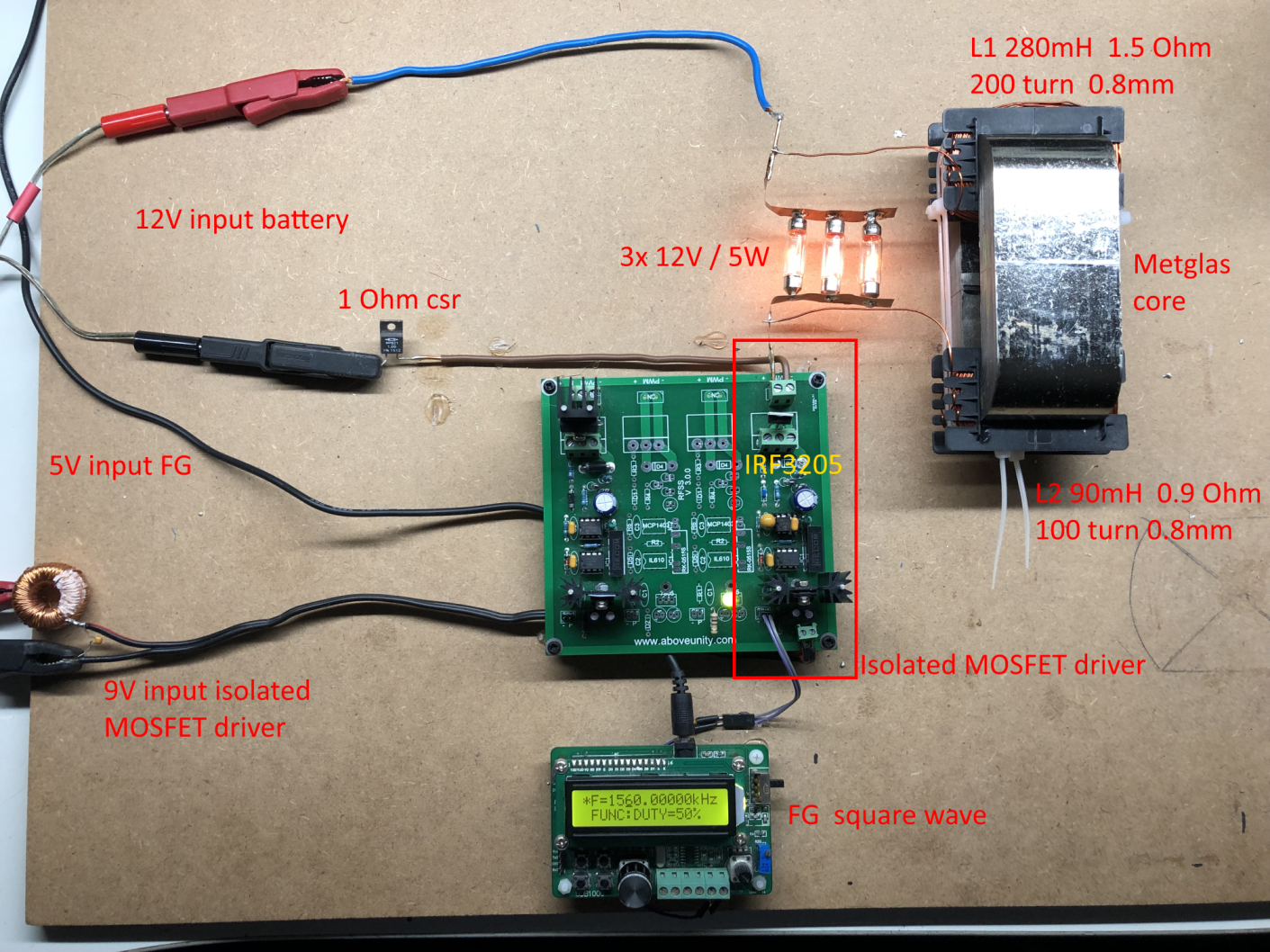
I have build up a similar circuit and the data is shown here: 
(Be aware that the induction measurement was done at 10kHz, but due to the influence of the metglas core it can be (and is) completly different on other frequencies, see my thread on OUR.com for a VNA scan of the coil/core)


I am using a 12V battery for now as my PS (minus NOT grounded) was acting weird due to all the pulses coming back from the ZPE device.
Up till now no special effects or resonance in a 0 to 5MHz range are seen with this setup, but as said the grounding may be the problem here.

Itsu

Itsu posted this 24 November 2022

Quoting:YoElMiCrO

Hello everyone.

@ Itzu.

I tell you from my point of view what happens in ZPM of Fighter.

Let me explain...
The first thing that has to happen is that the core is deeply saturated,
When two magnetic fields are faced and the mutual coupling is 
less than 1 as in this case, what happens is that the magnetic permeability falls and
Lenz's law as we know it does not appear.
This current being so high, in the case of Figther the mosfet use
is the IRFP250 which has an Rds(on) of 85mOhms and the supply voltage
of 25Vdc.

The Ton time will be that necessary for the two magnetic sections of the core to be
are in magnetic permeability of the vacuum and that depends on H, this
between 1.3 to 3 Hc and it is clear that it depends on the core material.
Now...
The duty cycle that Fighter used is 25%, let's calculate the worst case...
The maximum current that can circulate through the core will be...
ip=edc/(rcu + rds (on)).
The instantaneous power Pp=Edc*Ip will be dissipated in the Sw and copper of the transformer.
The power delivered as an average for the supply source...

Pp*(Ton/T).
But as you will see during the time of Ton the power that comes out of the source of
supply is very large and has to dissipate partly in the Sw.
That's why it has to warm up as Fighter says.
Also that's why the source capacitor is, because it has to support
tremendous variation of current.
Moreover due to this same high current the cables leaving the source
up to ZPM behave as inductors and it will be the electric field who
during the Toff cycle will feed the source, the ZPM windings will feed
to the load that is parallel to them making use of the electric field that
was disturbed during the Ton cycle
I don't know if I make myself understood.
I have the entire ZPM mathematical model of Fighter developed,
It has many anomalies, that's why I'm still studying it.

Thanks you.

YoElMiCrO.

Thank you.

YoElMiCrO,  Fighter,

going back to this nice post from YoElMiCrO, is it possible to apply those formulas to Fighters setup like i did?

Could it be shown then that Fighter his setup is causing his core to saturate, and that there is a strong current going back into the MOSFET causing it to heat up etc.

By the way, how to check if a core is saturated?  By monitoring the coil current to suddenly increase?


Thanks,   Itsu


YoElMiCrO posted this 24 November 2022

Hello everyone.

@ Itsu.

Thanks for the compliment...
It's not magic, it's electronic.
For 10 years I have been dedicated to the design of power electronics,
before that to telecommunications, also to design!.
I've been in electronics for 40 years, it is said soon, hehehe.
Well, changing the subject...
I think the universe around us is purely electric!
That's why I take a master's degree in particle physics,
but without time, thank goodness I go to my ball!

I think to achieve OU we need to excite the electrical medium.
That before us was done by Nikola Tesla (NK.T.), then another doctor...
Konstantin Meyl.
The Fighter ZPM is the modern version of the Harpin.
In the time of NK.T. there was no way to circulate high currents
in a winding, that's why he use spark jumps and an inductor
very small, so that KA circulated at the time of discharge
of its capacitors.

We have advantages over him, if he lived in this time
we would already have UFOs of humanity.
In fact, I have verified that PI/2 is a constant for waves
longitudinal, which shows that the speed of light
It's just a constant for our dimension.
I think that's why we never contact beings
alien to the earth, they do not employ Hertzian waves.
There is a lot to discuss...
But the time will come!

Thank you.

YoElMiCrO.

Itsu posted this 24 November 2022

YoElMiCrO

thanks for the information, so you have a lot of experience under your belt, very good and very needed.


But what about my questions above, is there any chance your are able to answer those together with Fighter?

I know you need some data from Fighter and that Fighter is very busy right now, but perhaps some data is already available to make those calculations.
It could show the reason for his MOSFET heating up and perhaps explain some other things like if the core saturates and when.

But all in your and Fighters own time of course.

Itsu

YoElMiCrO posted this 24 November 2022

Hello everyone.

@ Itsu.

The saturation of the core is easy to see,
you will see that the current grows linearly to a point
where it begins to rise steeply.
For your case you need a duty greater than 25% or increase
you turn them out or raise the supply voltage.
This image shows approximately the waveform
that you should have in the current sense resistor (CSR).

I hope it helps you.

YoElMiCrO.

Itsu posted this 25 November 2022

YoElMiCrO,

thanks, that helps, i see what you mean.

Trying to get this saturation point of my core / coils (lamps disconnected, so only the 2 opposing coils being switched).
PS set to 24V, current probe measuring the input current as per YoElMiCrO his above diagram.
I had to lower the frequency to 500Hz to be able to get a nice current wave form.
MOSFET used is a IRFP260N without heatsink and directly driven from my little SG/FG.

Yellow is the Gate signal of the MOSFET,
Green the input current using my current probe.
Duty cycle varied from 25% to 50% to 75% and 90%.
From 90% duty cycle, the current starts to move from the zero line, but i still do NOT see the saturation point (bend upwards).
There is ONLY 700mA average flowing through the MOSFET at 90% duty cycle, so hardly getting warm.
4 screenshots shown below.


So i am not able to get the core saturated with 24V and average 700mA flowing through the coils it seems.

Itsu

Itsu posted this 26 November 2022


I was using IRFP260N MOSFETs, but if i increase the duty cycle above 90%, the current trace starts elevating from the zero line even more causing the MOSFET to blow up.

Increasing the input voltage from 24V to 40V to increase the current so it would saturate the core resulted in this elevation from the zero line to happen already around 75% and again blowing up the MOSFET.

Never i saw the current increase above 5A or so (MOSFET is capable of 50A), so i think the MOSFET is blown due to the BEMF pulse.
Monitoring the Drain shows indeed the flattopping of the BEMF pulse around 220V pointing to avalancing of the MOSFET leading to heating up quickly and its destruction.

So it looks to me that the IRFP260N MOSFET and similar types of MOSFET are not able with this setup to saturate the core,  but i am willing to do some further tests so any input on this is welcome.

Attached a PDF dealing with avalanching of a MOSFET

Regards Itsu

Attached Files

YoElMiCrO posted this 26 November 2022

Hello everyone.

@ Itsu.

I will try to make myself understood, I say I will try
because I'm not good at it!

Looking at what you published, I tell you...
Usually the maximum duty you can use
In an inductive load it will always be 50%, this is due to
that the core needs a reset time, this is to arrive
to the same point where I start, otherwise it will climb
the current, it is said that I enter continuous mode in current.
It must always be fulfilled that VpTon = VfbToff.
It can exceed 50%, but at the moment it is not relevant.
The current did not increase to 0 because it had not yet released
all the magnetic energy contained in the core during
Toff's time.

I don't think MOSFET is the cause of it not saturating,
in fact I see that during the time of Ton the drain is
almost to potential 0.
The MOSFET was destroyed because it exceeded both parameters
in the Drain/Source feature.
In an inductor what is conserved is the current, this means
that if when the Ton cycle ended the current was 700mA
as in your case and the difference of turns is 100, now between the
two terminals are 0.7A*100=70A, but the MOSFET goes into avalanche
because during the Toff cycle Vds will be 70A*(Vds(max)/Ifuga), then
to enter driving by this avalanche, because imagine...
The core has to saturate yes or yes.
There is no gap between the two halves of the cores?.

Ok, let's do a test...
Take just one winding, any...
FG in 100Hz and varies the DTC from 1uS to 5000uS.
Then the other, you will see that the one who has more turns needs
more time than Ton with respect to the other.
Then both in non-inductive mode, as you had!
It must saturate at a shorter time than the one with the fewest turns.

I hope it helps you.

YoElMiCrO.

Itsu posted this 27 November 2022

Replying To: YoElMiCrO

YoElMiCrO 

thanks for your help and explanation, much appreciated.

You say:  "in fact I see that during the time of Ton the drain is almost to potential 0", but i did not show the drain signal, only the gate and input current, so i wonder how you see this.

Anyway, there are no gaps between the two halves of the cores, they are tied together using 2 tiewraps.

I do not understand your test, you want me to put on an extra one winding coil/turn around the core somewhere or use one turn from one of the 2 existing coils?


Below i added the drain signal, so green is input current, yellow drain MOSFET and blue gate MOSFET referenced to minus/ground.
41V input, 500Hz, 90% Duty cycle, and MOSFET gets hot very quickly.

Itsu.

Itsu posted this 27 November 2022


Here i am using a 1200V, 17A, 224mOhm MOSFET NVH4L160N120SC1 at 41V input, 500kHz / 11% Duty Cycle which already shows BEMF pulses around 1500V just before it starts to flattop (avalanche).

Average current is very low and shows no sign of saturation of the core.

If i increase the duty cycle the MOSFET drain signal starts to flattop (avalanche), will heat up the MOSFET quickly and  dies.

Itsu

Vidura posted this 27 November 2022

Replying To: Itsu

Hi itsu. When I tried to replicate I had the same issue, without load the current was insignificant. To avoid very high stress on components, it's a good idea to put a MOV in parallel to the switch. For the test of saturation it might be better to decrease the frequency instead of rising the voltage or duty cycle very much. When you connect any load in parallel with the inductor, there should appear a DC current in reverse direction, which would add a offset to the current and saturation would be easier. Maybe try different values of load resistance? Best wishes.

Vidura

Close