Fighter
posted this
09 November 2022
Replying To: Itsu
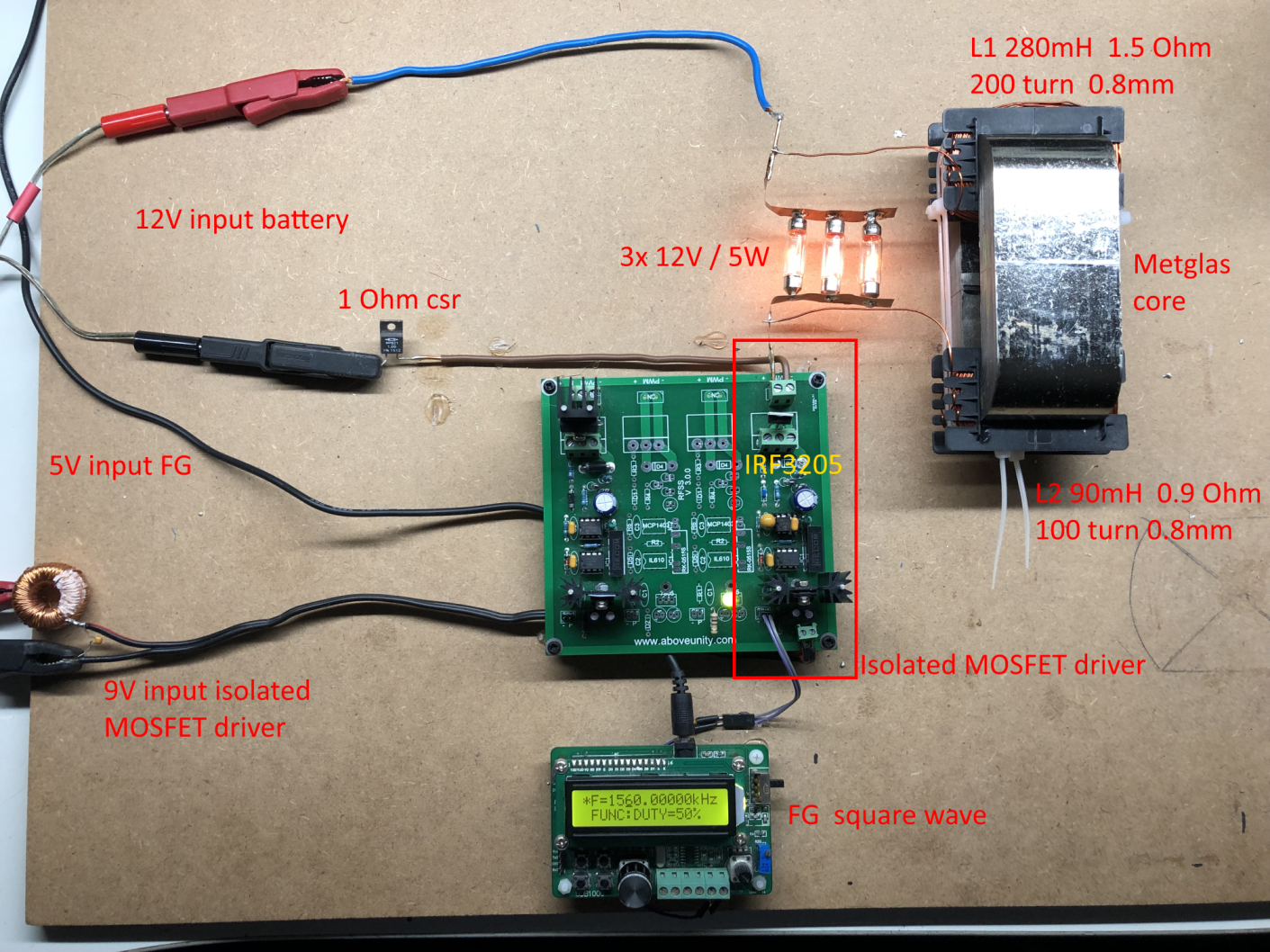
As Fighters device is so simple i cannot imagine that it acts like a generator
Well, it looks simple as long as we don't have the instruments to see with our own eyes what the fields created around the core are doing. But still it is a generator.
I will put a quote about ZPM from YoElMiCrO here, I don't doubt his expertise and I hope he doesn't mind for quoting him:
The best experiment I've ever seen real is your ZPM. I've been studying what's going on all this time in it and I think I finally have the answers. At least from an electronic point of view. It has to do with the vector A.
In your case, as in the Hairpin of N.Tesla is this vector who really feeds the load and does not your source.
Your ZPM creates two asymmetric A vectors, if only in three Dimensions would be a double torus, one larger than the other. In fact one is half of the other.
Remember that when you apply Ton to your ZPM, the H fields are found, this causes your leak inductance to grow around the core. It does this over each section of the kernel.
"So simple" you say ? 🙂
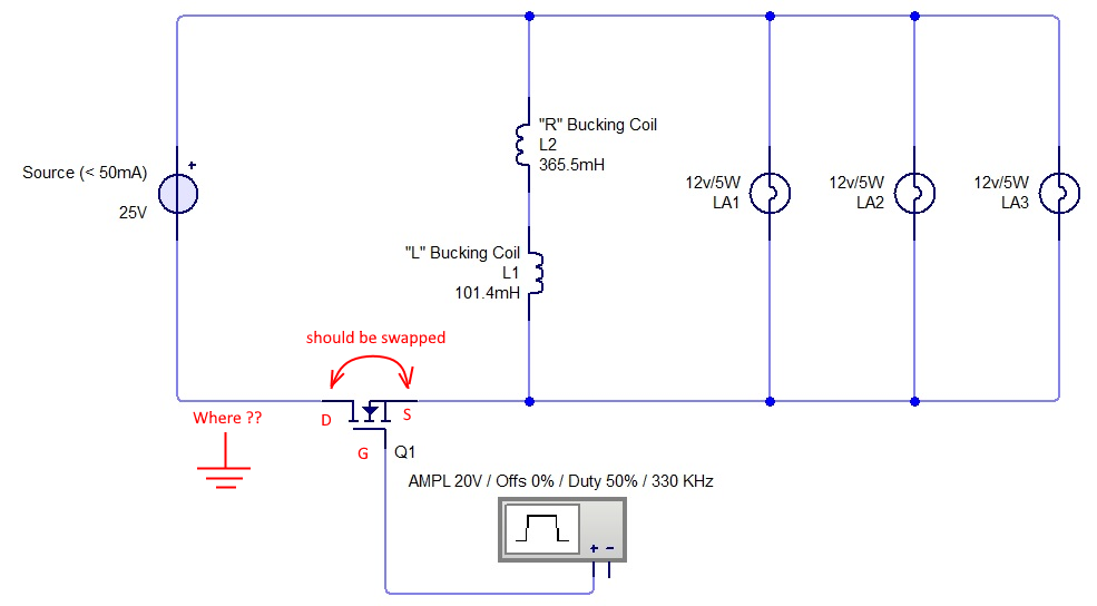
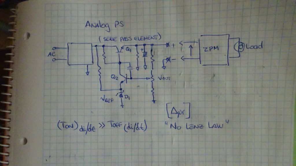
Let's look at it from the point of view of the "official" physics. We have a device creating two pulsed magnetic fields fighting/annihilating each other. It should be almost the ideal case of "how to waste all the input power and obtain nothing on output", isn't ?
Basically no matter how much power we would put on input the device should waste almost all of it and there should be not enough power remaining to power let's say 2 x 12V/55W light bulbs. But still the light bulbs are shining, the DC source's transformer is not destroyed and the current limiter is not activated. Also, did you tried to measure the power sent back to the DC source by ZPM ? Don't forget about it, that is output too.
I think this power going back into the DC source is a problem...
... of readings ?
Personally I don't think it's the case.
From my point of view there is no issue with the DC source's readings and that was settled long time ago here:
https://www.aboveunity.com/thread/romanian-zpm-zero-point-module/?order=all#comment-6370ae2a-fc99-482f-bab3-aa7200cd760e
Because that was confirmed by a second measurement device:
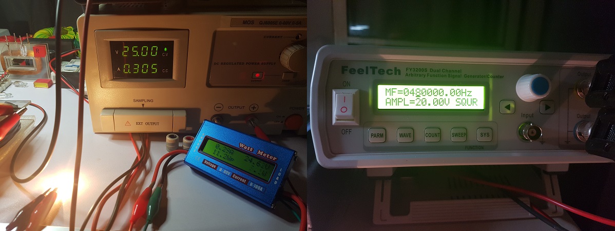

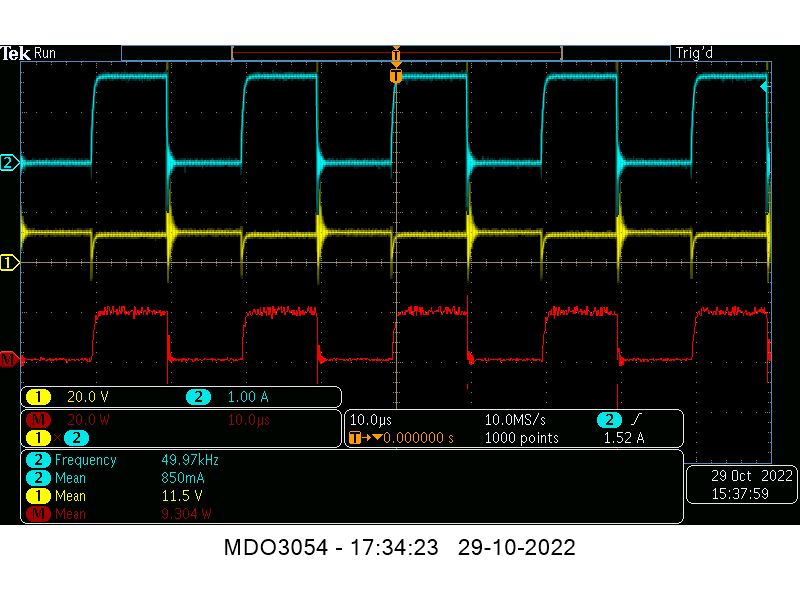
I "forced" ZPM out of the optimal/resonance frequency so the consumption would be higher because the wattmeter is not built to measure currents lower than 0.100 A.
The small current difference (~ 0.01A) is because the power meter itself have a small consumption.
The probability of ZPM messing the readings of two different devices (at the same ZPM frequency but with different components, different reading sensors, etc. ) but still the devices to show the same readings is the same as the probability to play at the lottery for the first time in life and win the big prize then playing for the second time and win the big prize again.
Technically and statistically the probability is 0.
Regards,
Fighter
| "If you want to find the secrets of the universe, think in terms of
energy, frequency and
vibration." |
|
|
Nikola Tesla |