Fighter
posted this
20 November 2022
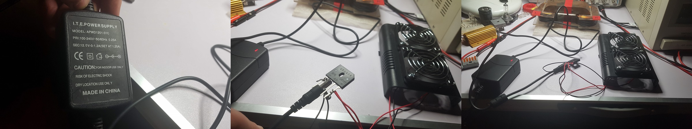
you were mentioning earlier MOSFET driver (like a TC4420), but i understand now you have no MOSFET driver in your circuit.
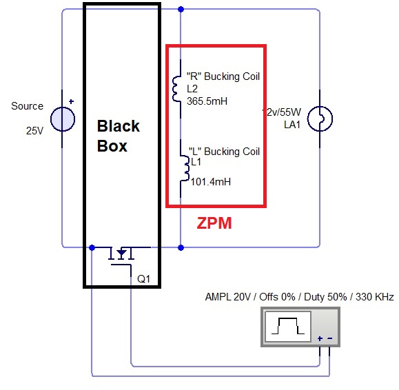
That is correct. I called the entire black box "MOSFET driver" just for convenience.
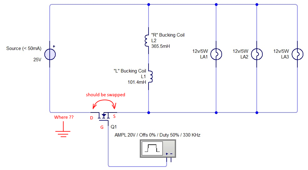
by the way, the MOSFET is drawn wrongly in your drawing, but i am sure you know this
Yes, just ignore that, I used an old image, the mistake was corrected at some point later.
if I remember correctly Fighter also could make it work with the switching module, it is completely isolated with optocoupler and galvanically separate driver power supply
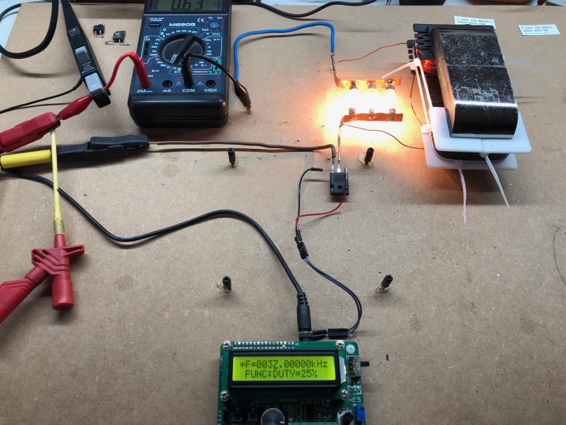
You remember very well, Vidura, I used the PowerTool designed and built by you. And it's completely isolated and the ZPM was running fine with it.
More info about Vidura's PowerTool can be found here:
https://www.aboveunity.com/thread/switching-tool-users-guide/
And more info about the test can be found here:
https://www.aboveunity.com/thread/romanian-zpm-zero-point-module-enhancements-stage/?order=all#comment-e6214e64-b171-40ca-86b4-aae60130f58d
And there is also a video with the experiment:
I believe the issue is in the core, there are many different types of metglass, and the nonlinearity of permeability is essential for parametric excitation
It's a possibility, unfortunately I have no method to make a distinction between Metglas cores wich work with ZPM and cores which don't work with ZPM.
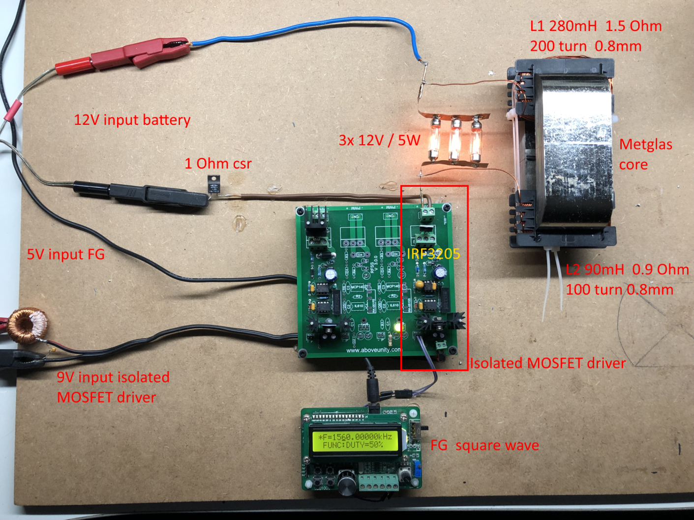
The core I used for ZPM prototype is a Hitachi Metals core, the details about it are here:
https://www.aboveunity.com/thread/romanian-zpm-zero-point-module/?order=all#comment-68d2066a-bffa-4106-9204-aa7100f602d5
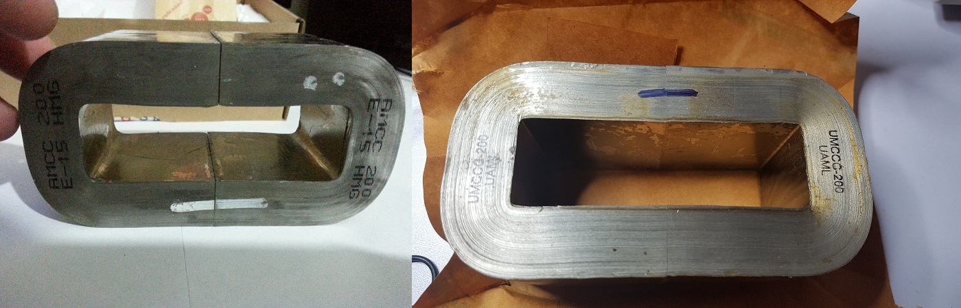
And the core I used for the ZPM replica is a UAML India core, the details about it are here:
https://www.aboveunity.com/thread/romanian-zpm-zero-point-module-enhancements-stage/?order=all#comment-d100b5a9-5d83-4f16-9cca-ab5300cb415b
Itsu, could you provide more details about the source and characteristics of your Metglas core ? Could be useful to make an idea about it.
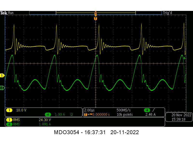
Also, if it's possible, could you take a screesnhot of the oscilloscope in a test when it shows the ZPM-specific waveform pattern ? I would like to compare it with the waveforms and readings (especially Vpp) shown by my ZPM prototype and ZPM replica, maybe it's something there which could give us an idea why the input decrease doesn't occur in your tests.
Fighter
| "If you want to find the secrets of the universe, think in terms of
energy, frequency and
vibration." |
|
|
Nikola Tesla |