Fighter's ZPM (Zero Point Module) failed replication by Itsu

  • 8.1K Views
  • Last Post 18 December 2022
Itsu posted this 07 November 2022

Hello all,

i opened this thread to discuss my replication of Fighter's ZPE (Zero Point Module).

I already opened a similar thread on OUR.com (https://www.overunityresearch.com/index.php?topic=4374.msg101654#msg101654 ), but will transfer some data from there to here.

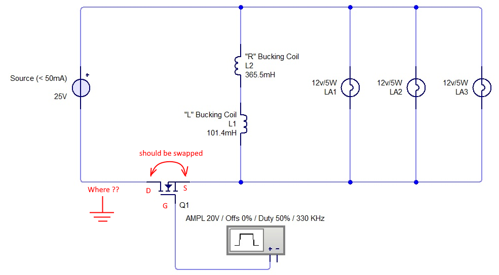
Initially i understood that the below diagram was correct and complete, but it turns out its not.
There is a ground connection somewhere, but i am not sure where it is exactly, hopefully someone can tell me.
The MOSFET is shown wrong as the Drain and Source should be swapped, which was corrected later in Fighter his thread so therefor the mentioning in red.

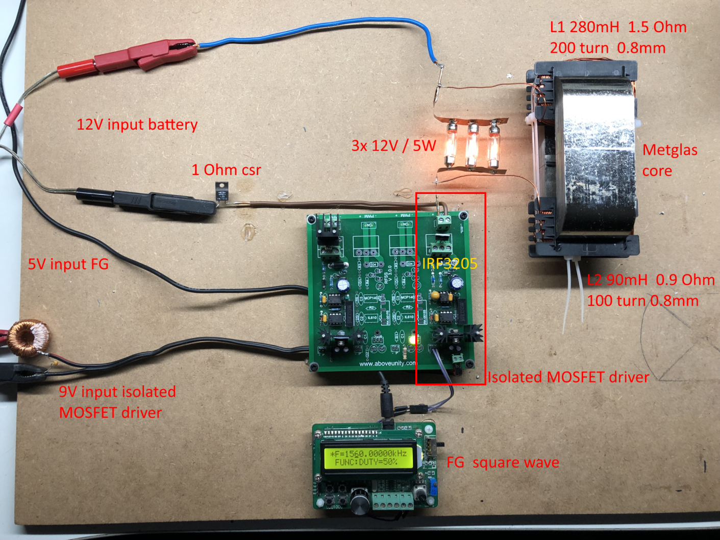
I have build up a similar circuit and the data is shown here: 
(Be aware that the induction measurement was done at 10kHz, but due to the influence of the metglas core it can be (and is) completly different on other frequencies, see my thread on OUR.com for a VNA scan of the coil/core)


I am using a 12V battery for now as my PS (minus NOT grounded) was acting weird due to all the pulses coming back from the ZPE device.
Up till now no special effects or resonance in a 0 to 5MHz range are seen with this setup, but as said the grounding may be the problem here.

Itsu
Itsu posted this 23 November 2022


YoElMiCrO

thanks for your insights, it seems you have it nicely figured out and presented clearly πŸ‘

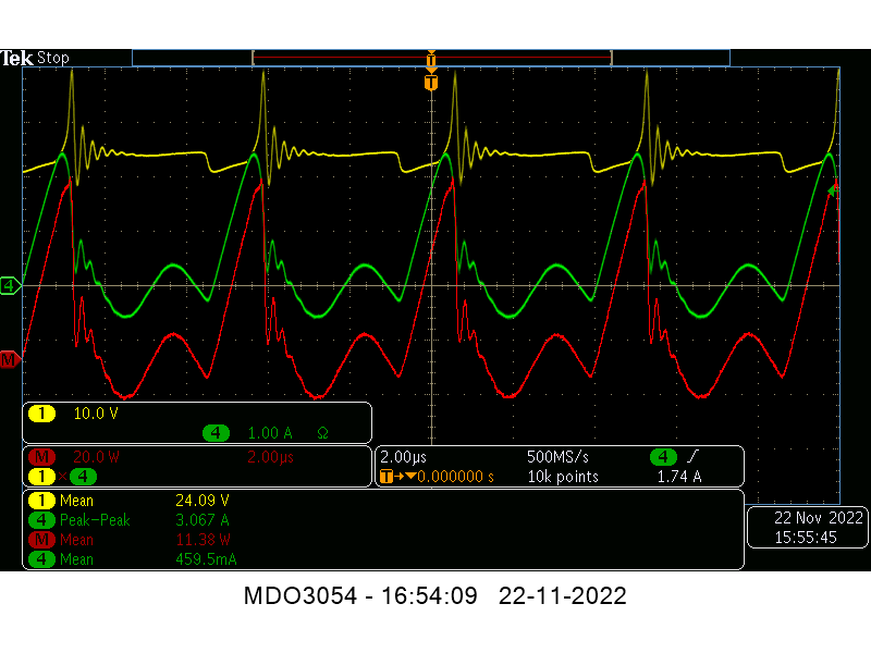
If we apply your formulas to my situation we have this screenshot there: 


Yellow input voltage 24V
green input current 
red math function yellow * green = input power
we see little current going back into the DC source and we have following data:

Rcu is 0.9 + 1.5 = 2.4 Ohm,
Rds (on) = 0.055 Ohm (IRFP260N)
Edc = 24V
Freq. 213kHz / T = 4.7us
Duty cycle = 25%   Ton = 1.175us

thus according to your formulas we have:

Ip = Edc/(Rcu + Rds (on))
Ip = 24/2.455 = 9.77A

and:

Pp = Edc*Ip
Pp = 24*9.77 = 235W

Pavg = Pp*(Ton/T)
Pavg = 235*(1.175/4.7) = 58.7W

But as can be seen in the screenshot, the Ip is much less (3A), and thus Pavg (11.38W)
This Pavg is so low that my MOSFET is barely heating up without heatsink.

So i wonder where the difference comes from between your calculations, my results and Fighters results.


Regards Itsu

Vidura posted this 23 November 2022

Here I will put a video from a test that I made earlier:

Despite that I didn't get resonance, the observed DC component could cause the saturation of the core and explain the high curre during t-on

Vidura

YoElMiCrO posted this 23 November 2022

Hello everyone.

@ Itsu.

No, it's not!
That current you calculated is the maximum possible
to extract from the source for your replica.
In your case the current is triangular, it is logical due to
to the total inductance connected to the Sw.
The inductance would be...
Lt=(N2-N1)(N2-N1)Al.
Its di/dt=Edc/Lt.
Since Rds(on) is much smaller than Rcu, it is negligible.
That's why your mosfet doesn't heat up, in fact it doesn't work for you.
because the core is not saturated...
For your case, the calculation would be as follows...
Ipk=EdcTon/Lt=3A.
Pdc=(0.5IpkEdcTon)/T+Losses due to joule+ effect lost by Sw+ those of the core, etc.
Pdc=(0.5*3*24*1.175)/4.7=9Watts.
In touches the losses would be...
11.38-9=2.38Watts.
Your efficiency would be...
(9/11.38)100=79.36%~80%
A normal case for electronics as we know.

I hope it helps you.

YoElMiCrO.

Itsu posted this 23 November 2022

Quoting:Vidura

Here I will put a video from a test that I made earlier:

Despite that I didn't get resonance, the observed DC component could cause the saturation of the core and explain the high curre during t-on

Hi Vidura,

thanks for your video / tests.

You mention you have no resonance, but you also mention that the neon bulb lights up due to resonance, so i wonder how that can be.
Does a neon bulb not light up at anything above 45 and 65VAC regardless there is resonance or not?
See my earlier post where i measured the centerpoint between the 2 coils to have something like 90V:
https://www.beyondunity.org/thread/fighter-s-zpm-zero-point-module-replication-by-itsu/?p=6&order=all#comment-a0987e26-9f7a-4428-8de7-af4b0020f571

Anyway, another point of interest is your statement about the used FG as it is somewhat "weak" compared to other FG's, so i might try another stronger FG to drive the MOSFET.

Thanks Itsu

Itsu posted this 23 November 2022

Quoting:YoElMiCrO

Hello everyone.

@ Itsu.

No, it's not!
That current you calculated is the maximum possible
to extract from the source for your replica.
In your case the current is triangular, it is logical due to
to the total inductance connected to the Sw.
The inductance would be...
Lt=(N2-N1)(N2-N1)Al.
Its di/dt=Edc/Lt.
Since Rds(on) is much smaller than Rcu, it is negligible.
That's why your mosfet doesn't heat up, in fact it doesn't work for you.
because the core is not saturated...
For your case, the calculation would be as follows...
Ipk=EdcTon/Lt=3A.
Pdc=(0.5IpkEdcTon)/T+Losses due to joule+ effect lost by Sw+ those of the core, etc.
Pdc=(0.5*3*24*1.175)/4.7=9Watts.
In touches the losses would be...
11.38-9=2.38Watts.
Your efficiency would be...
(9/11.38)100=79.36%~80%
A normal case for electronics as we know.

I hope it helps you.

YoElMiCrO.

YoElMiCrO

you are a wizzard with formulas πŸ‘

So you think my main problem is that my core is not saturated.

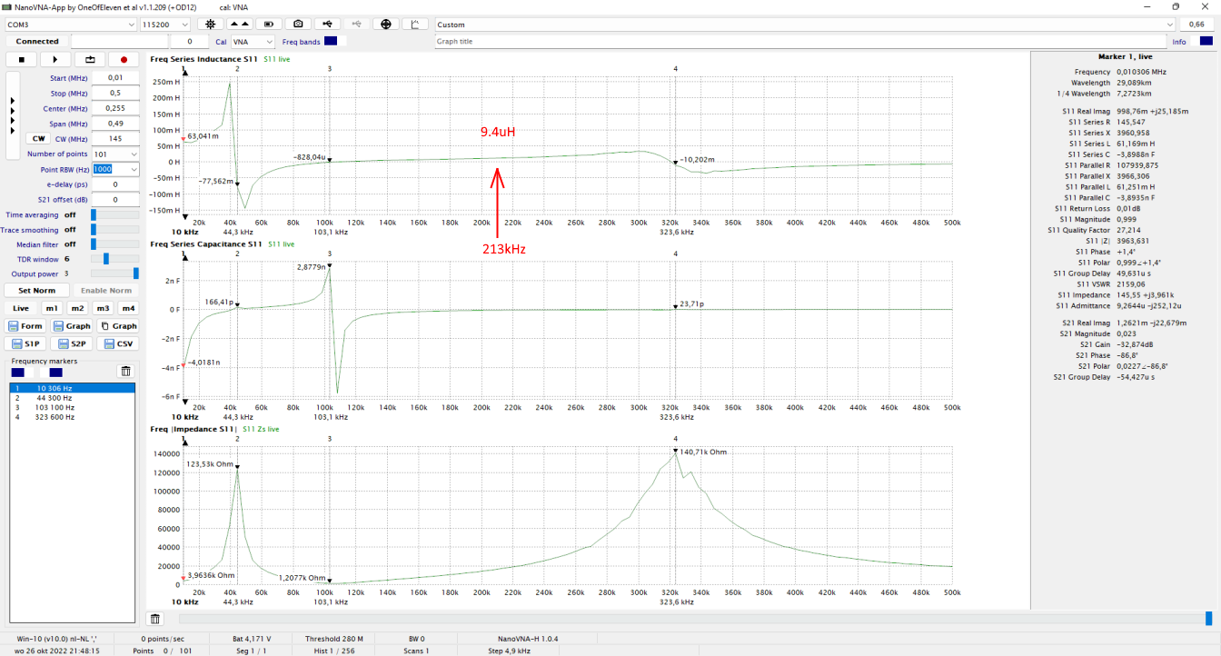
Using your formula; Ipk=EdcTon/Lt=3A i can calculate my inductance Lt (at 213kHz) by:
Lt = EdcTon/Ipk 
Lt = 24*1.175us / 3 = 9.4uH 

Looking at my inductance sweep using my nanoVNA which i showed on my OUR.com thread here:  https://www.overunityresearch.com/index.php?topic=4374.msg101682#msg101682
It seems very close looking at the 213kHz line (marked red):


So i guess i have to find myself a real Hitachi AMCC 200 core and put up 2 full coils like Fighter 300 turns and 150 turns (i now have 200 : 100 turns), and hopefully it will saturate.

Thanks,  Itsu


Fighter posted this 23 November 2022

Quoting:Itsu

YoElMiCrO

you are a wizzard with formulas πŸ‘

Yes he is... ☺️ Yoel's posts are always insightful, I learned that while presenting my experiments with ZPM but also while making other experiments. He always make people think and see things from a different and fresh prespective.

Quoting:YoElMiCrO


So you think my main problem is that my core is not saturated.

...

So i guess i have to find myself a real Hitachi AMCC 200 core and put up 2 full coils like Fighter 300 turns and 150 turns (i now have 200 : 100 turns), and hopefully it will saturate.

... Or before getting a Hitachi core try with 150/300 turns on the actual core, why not ?

If that would saturate the core and it works correctly as ZPM then you can use your actual core not only for ZPM replication but also for future MEG replication.

If not then the second option is to get a Hitachi core I guess.

Fighter

"If you want to find the secrets of the universe, think in terms of energy, frequency and vibration."
Nikola Tesla
Vidura posted this 23 November 2022

Quoting:Itsu

Quoting:Vidura

Here I will put a video from a test that I made earlier:

Despite that I didn't get resonance, the observed DC component could cause the saturation of the core and explain the high curre during t-on

Hi Vidura,

thanks for your video / tests.

You mention you have no resonance, but you also mention that the neon bulb lights up due to resonance, so i wonder how that can be.
Does a neon bulb not light up at anything above 45 and 65VAC regardless there is resonance or not?
See my earlier post where i measured the centerpoint between the 2 coils to have something like 90V:
https://www.beyondunity.org/thread/fighter-s-zpm-zero-point-module-replication-by-itsu/?p=6&order=all#comment-a0987e26-9f7a-4428-8de7-af4b0020f571

Anyway, another point of interest is your statement about the used FG as it is somewhat "weak" compared to other FG's, so i might try another stronger FG to drive the MOSFET.

Thanks Itsu

Some parts of the video I didn't remember, yes there was a resonance when the load was not attached, at low frequency, but with the load I failed to get the effect like fighter at several hundred kHz. Regarding the SG , I discovered when working with the switching module, that a square wave with the same amplitude as a microcontroller for comparison delivered only around half of the current with the same load (led of the optocoupler and serial resistance)attached.

Vidura

Itsu posted this 23 November 2022

Replying To: Fighter

... Or before getting a Hitachi core try with 150/200 turns on the actual core, why not ?


Yes, i could do that, but need to order more 0.8mm magnet wire as i did ran out of it during the winding of the first ZPM therefor only 100/200 turns.


Itsu

Itsu posted this 23 November 2022

Replying To: Vidura

Thanks Vidura,

i know these little Chinese SG's i use now are weak in signal, but the switching board (with MOSFET driver) boosted the signal, but now i am running this SG straight to the MOSFET, so it might fail to switch properly or so.

I will see.

Itsu


Fighter posted this 24 November 2022

... Or before getting a Hitachi core try with 150/200 turns on the actual core, why not ?

Correction, I just noticed this mistype, I meant to say 150/300 turns, I edited my previous post.

Fighter

"If you want to find the secrets of the universe, think in terms of energy, frequency and vibration."
Nikola Tesla
  • Liked by
  • YoElMiCrO
  • Inception
Close