Fighter's ZPM (Zero Point Module) failed replication by Itsu

  • 8.1K Views
  • Last Post 18 December 2022
Itsu posted this 07 November 2022

Hello all,

i opened this thread to discuss my replication of Fighter's ZPE (Zero Point Module).

I already opened a similar thread on OUR.com (https://www.overunityresearch.com/index.php?topic=4374.msg101654#msg101654 ), but will transfer some data from there to here.

Initially i understood that the below diagram was correct and complete, but it turns out its not.
There is a ground connection somewhere, but i am not sure where it is exactly, hopefully someone can tell me.
The MOSFET is shown wrong as the Drain and Source should be swapped, which was corrected later in Fighter his thread so therefor the mentioning in red.

I have build up a similar circuit and the data is shown here: 
(Be aware that the induction measurement was done at 10kHz, but due to the influence of the metglas core it can be (and is) completly different on other frequencies, see my thread on OUR.com for a VNA scan of the coil/core)


I am using a 12V battery for now as my PS (minus NOT grounded) was acting weird due to all the pulses coming back from the ZPE device.
Up till now no special effects or resonance in a 0 to 5MHz range are seen with this setup, but as said the grounding may be the problem here.

Itsu

Itsu posted this 12 November 2022

Quoting:Vidura

Replying To: Itsu


It refers to an effect which appears with parametric resonance, on the tap between the two coils a very high potential appears, it is likely that a neon globe will lite when approaching this area. It depends on the relationship of the inductors and other parameters. It is very similar to the hot end of a Tesla resonator.


YoElMiCrO,   Vidura,


OK, i  checked with a neon bulb at that centerpoint between the coils, but no light, then i used a free floating probe next to this junction, but no strong signal noted, so i used my HV probe there to show the signal when in resonance without load and this screenshot shows the signal there:

Yellow: HV probe at centerpoint between the 2 coils referenced to return/ground,

Purple: gate signal


Itsu

Itsu posted this 12 November 2022

Replying To: Fighter

Thanks Fighter,

seems interesting, i will read your thread and watch the video lateron.

Itsu


Itsu posted this 12 November 2022

Quoting:Shelfordella

Quoting:Itsu

Quoting:Shelfordella

When the switch closes, the source is powering the coil and the load, maybe it will be working if a second switch is added between the coil and the load with an inverted  driving signal, so the load is powered only by the coil.

Shelfordella,


thanks for the idea, might be something to look at to separate the BEMF pulse from the input.

Itsu 

Hi Itsu,

you're welcome. That's not exactly what I meant, but this is a good idea  to try too. What I meant was separating the input pulse from the load, so that a pulse only powers the bucking coils. Also, the resonant frequency is dependent on the time constant L/R, more load in parallel equals less resistance equals higher time constant equals lower pulse repetition rate required to complete a full cycle. There isn't really a resonant frequency, but instead an optimal repetition rate.

Ok,  yes i know what you mean, i will see if i can set up an experiment later.

Thanks,  Itsu


Itsu posted this 15 November 2022


I made an overview video to show how my setup is right now after having tried severall other setups like different bulbs (21W bulbs) and severall (5) other power sources.

I did notice some resonance points, but all at different frequencies depending on the power source (or external filter) in use, so i think these resonances are mainly influenced by the used filtering in the used power supplies.
The battery (12V) did not show any resonance points across a 0 to 5MHz frequency range.

We have opposing magnetic fields as shown by the "Pole Detector" app (thanks Editor). 

Input power as shown by the scope never exeeds the power consumed by the 3x 5W parallel (15W) bulbs, so no need for accurate input / output measurements as i did in my thread on OUR.com.

So i am kind of out of options to find the anomaly shown by Fighter in his setup.

There are some things to try like removing the tension (currently 2 tiewraps) which holds the 2 core halfs together, or removing the isolation between the FG and MOSFET and/or attach the input voltage to the MOSFET driver to the same (oscillating / resonating) PS as the main circuit (now different PS's), but i think those are far fetched.

Anyway, overview video here:

Still suggestions are welcome.

Regards Itsu   

Vidura posted this 15 November 2022

Hi itsu Maybe you can get some useful idea from this videos: https://youtube.com/playlist?list=PLbhv9RvImM8zf8r5wWiF-JpUJ4jvXVlqI I am not sure as I could not replicate the effect of ZPM, but my latest hypothesis is that the presence of scalar waves in a standing wave resonator can pump current with energy extracted from the environment.

Vidura

Itsu posted this 16 November 2022

Vidura,

thanks for the link to your experiments, i am looking at these video's but have not seen them all yet.

I do notice you have also significant interference on your PS at times showing strange readings on its digital meters.

Also thanks for the confirmation that you were not able to "replicate the effect of ZPM" by which i understand the effect to be near zero input current while near full lights in the load bulbs.

 
Your hypothesis sounds very intriging however it consists of severall concepts like "scalar waves", "standing waves resonator", "pump current" and "energy extracted from the environment" from which not much coherent information can be found on the internet.

I will look at all your video's with your hypothesis in mind to get a better look on what you are trying to accomplish and how it can be used in my ZPM replication.

Thanks,   Itsu  

Vidura posted this 16 November 2022

Replying To: Itsu

I'm sorry for the terms, which can result a bit confusing. A scalar wave is a longitudinal pressure wave , expanding in all directions from it's source like sound waves. Their nature can be electric , magnetic or mechanical. In the recorded experiments standing waves have been observed, as indicated by the antinodes of current (flux) and potential (e-field). Also traveling waves can be involved in the case of a closed loop for example with a load connected. Both phenomenon producing scalar waves when the inductors are in resonance. In the first case the antinodes are fixed at certain coordinates of the installation. As it is a longitudinal phenomenon, it is likely that the wirelenght has a major effect. The advantage of the bifilares is that both conductors have not only the same number of turns, but also the same length, then one of these can be unwound by a certain number of turns. Also the coupling factor is higher and for the parametric resonance it seems to be convenient. Of course this is not the original ZPM Setup, but to try a bifilar on a single coil former could bring some insights as comparison anyway. I never tried this with the metglass core.

Vidura

  • Liked by
  • Shadow_
Itsu posted this 16 November 2022


Vidura,

thanks for your insights, yes those terms can be confusing as there is some info to be found on the internet on each separate term, but putting them together will yield practical no scientifical results.

But that's why we are here i guess to connect the dots and to come to something concrete with which we can work with.

Itsu  

Fighter posted this 17 November 2022

Quoting:Itsu

Still suggestions are welcome.  

Hi Itsu,

I was thinking a lot, at this point I don't know the cause why your replica is not producing the effect of minimizing the input.

But what I want to emphasize is the fact that what I presented is real and all the available data is public in the ZPM threads, there is no hidden information and no "trick" in my experiments and what I shown. I would never waste so much time to organize and present the data from my ZPM experiments and I would not waste my money just to present something fake. So what I shown is 100% real.

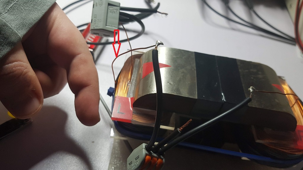
Now, first thing is I'd want to check something, I took 3 photos of my ZPM replica and I'm gonna show the direction of the windings for each coil and how they are connected together. This way you should have two pulsing North poles opposing each other at the top-middle of the core and two pulsing South poles opposing each other at the bottom-middle of the core.

This is a photo of the R (right) coil and the winding direction: the wire coming from the L (left) coil, the one marked by the red arrow, is going in the direction shown by my finger:

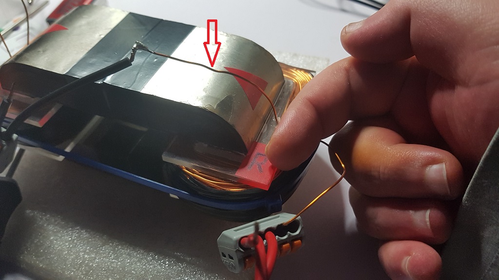
And this is a photo of the L (left) coil and the winding direction: the wire coming from the R (right) coil, the one marked by the red arrow, is going in the direction shown by my finger:

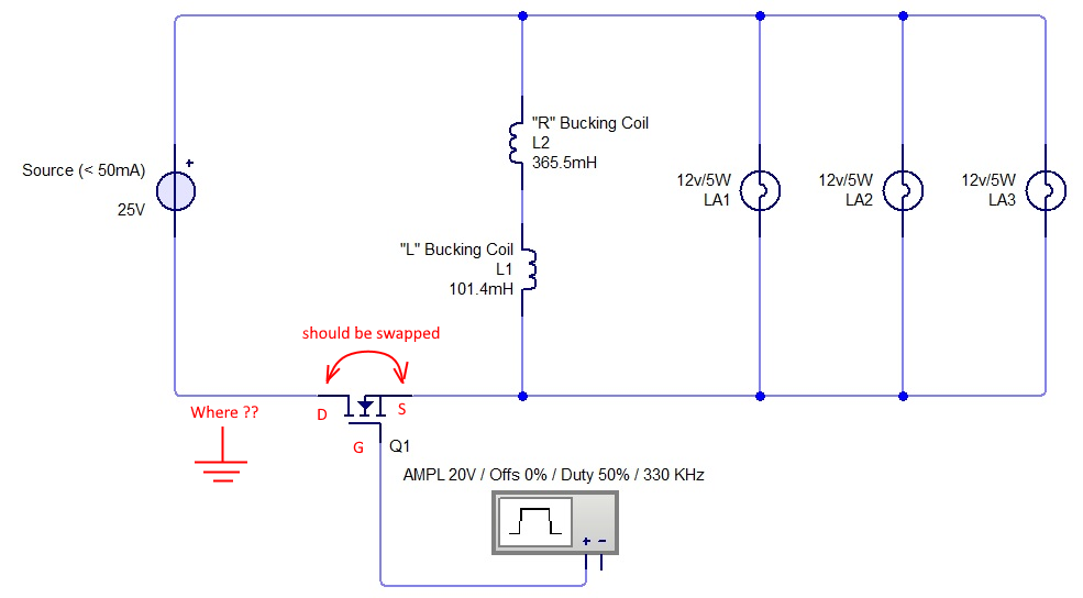
And this is how the other ends of the coils are connected to the circuit, the R (right) coil is connected to Positive coming from the MOSFET driver (basically directly from the Positive of the DC source) and the L (left) coil is connected to Negative coming from the MOSFET driver (from the Negative of the DC source but the connection is On/Off based on the MOSFET's command):

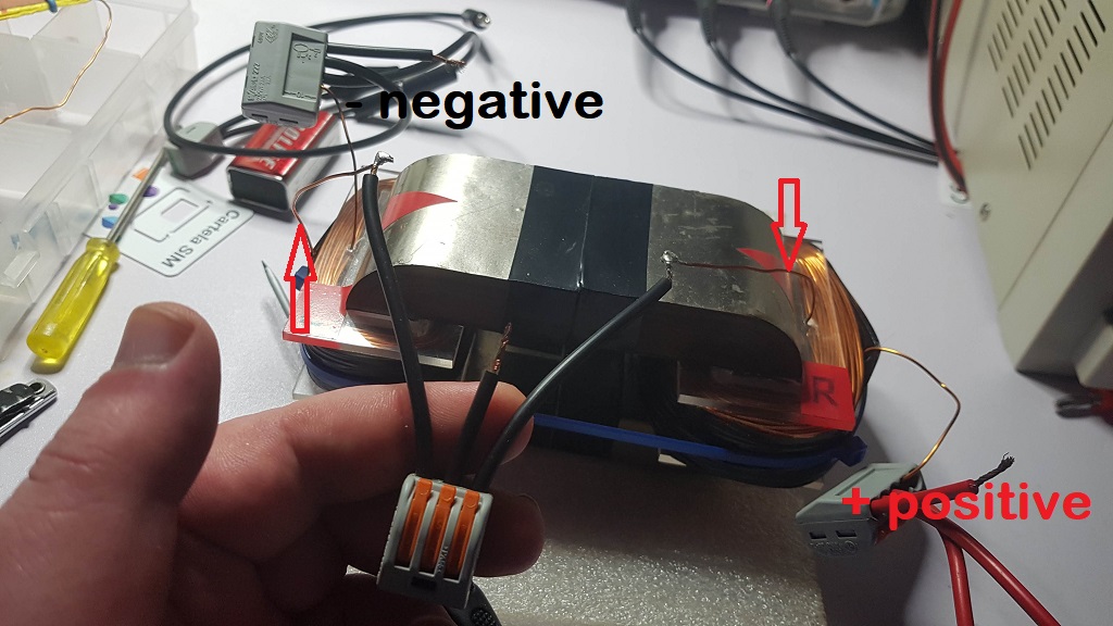
Also notice the beginning of the R (right) coil is connected at the end of the L (left) coil.

So let's check the replica's coils first, maybe there are differences causing the issue.

If they are okay, like in my photos, the second thing I would do is to try to use as close as possible my circuit with the DC power source powered from the grid and the grid having ground connection. Also the MOSFET driver being also powered from the DC source just like in my schema. My signal generator is also powered from the grid but ar this stage I don't think it matters if the signal generator is powered by grid or by a battery. At least I think it doesn't matter.

I mean I would get as close as possible to the schema I shown without things powered by batteries separately and stuff like this.

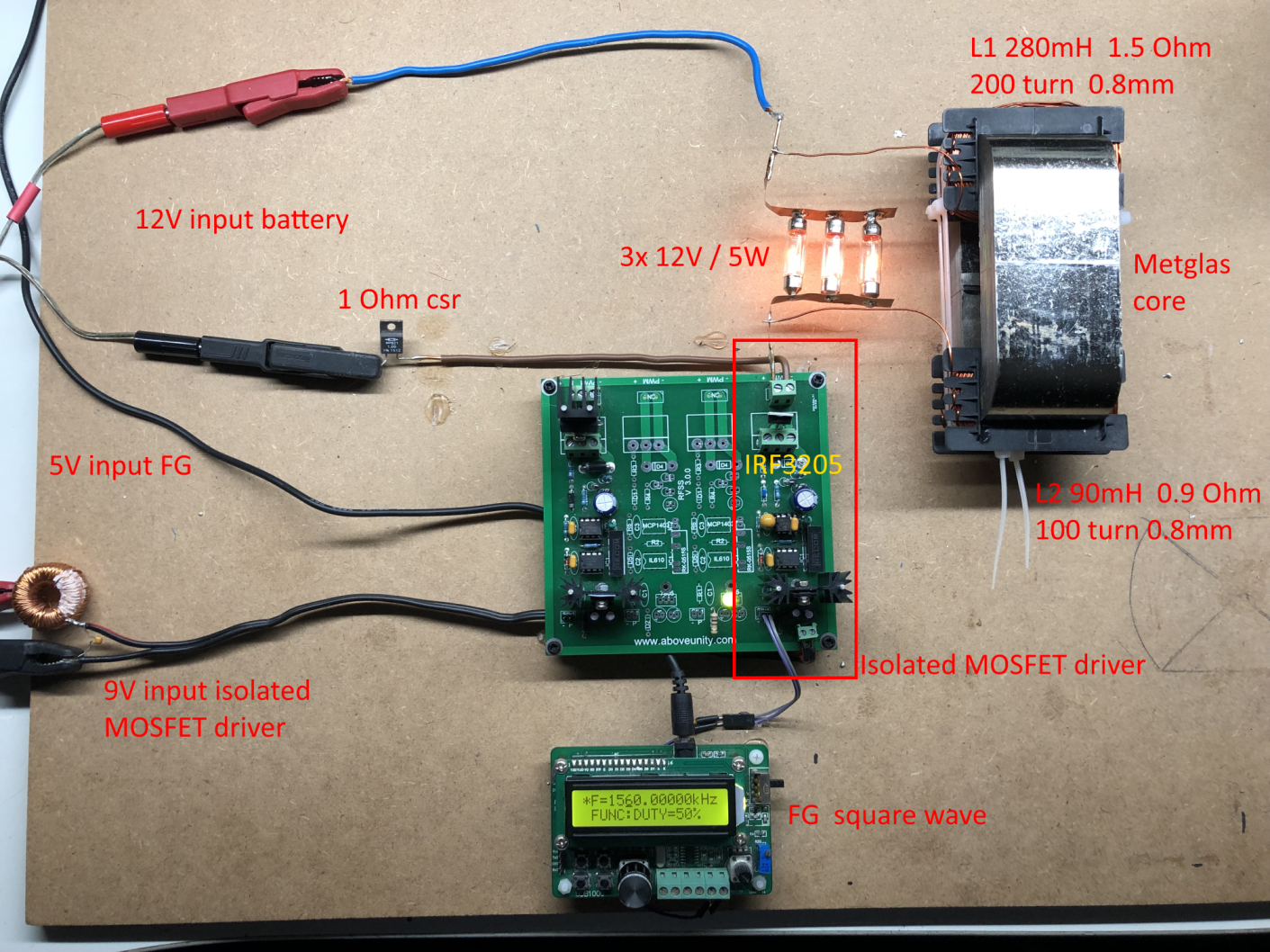
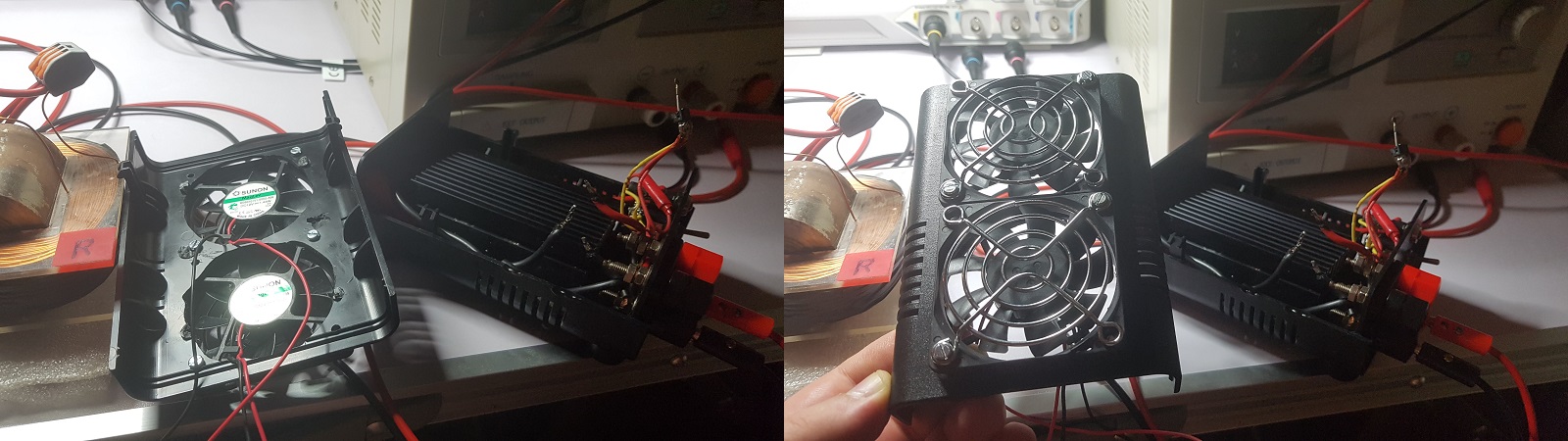
What intrigues me is why your MOSFET is not getting very hot very fast like it happens with my MOSFET (one of the channels of the black box I use with ZPM), in my case I need a big radiator and active cooling (two fans) in the MOSFET driver (the black box):

Regards,

Fighter

"If you want to find the secrets of the universe, think in terms of energy, frequency and vibration."
Nikola Tesla
  • Liked by
  • Shadow_
  • Vidura
Itsu posted this 17 November 2022


Fighter,

i do not doubt that what you see is 100% real, no problem there.

So yes, lets compare the coils first.

It seems there are some differences there.

What is your biggest coil? Coil R or L?   I have my biggest coil directly to the + of the PS

The winding direction seems the same (both pointing to the same direction like you show).

So your R coil inner wire is going to the L coil outer wire (my coils inner wires are connected).

When i swap the L coil inner and outer connection (like you have it), i have different poles south on top at one and north on top at the other which seems not OK.

Are you sure your coils are opposing (could you use that PoleDetector app like i showed in my video?).

Itsu

  • Liked by
  • Fighter
  • Shadow_
Close