Quoting:Itsu
Fighter,
thanks for the help, yes the devil is in the details they say.
No problem.
Yes, unfortunately I found it to be always true especially when I tried to replicate some other devices.
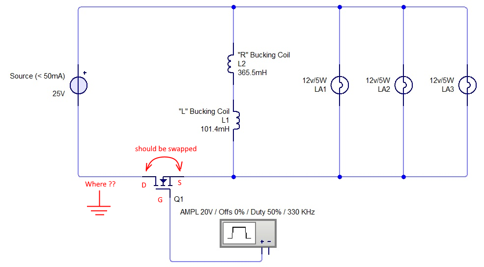
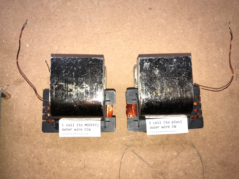
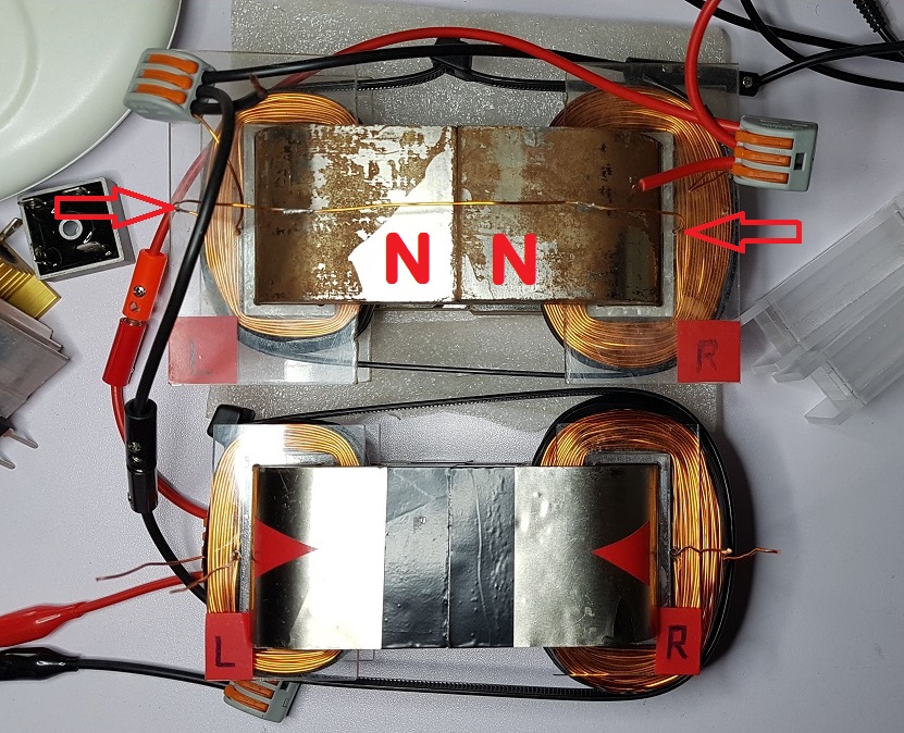
I will see if i can unwind one coil and rewind it the same way as the other then retest.
That's what I would do. Rewinding a coil should be no problem, I did it probably hundreds of times in my experiments...
You keep mentioning Akula or Don Smith's devices as examples, but to my knowledge nobody was able to do a succesfull replication of either devices, so taking them as good examples looks dubious to me at the least IMHO.
My teachers are Don Smith, Bearden, Melnichenko, Akula... all of them. I always try to listen to the details they present and to understand their way of thinking.
Personally I think all of their presentations are proofs their devices are real and working. I have no doubts about that.
Also I learn a lot from our members here who are very advanced in physics and electronics. And from the experiments they're sharing with the team. As a matter of fact just recently I learned something very enlightening from Jagau. There's always something new to learn from them.
Why do you think no one has replicated their devices ? You know very few researchers have the courage to come public and describe/show a replication or a working device. Most of them are afraid and don't want to take any risks as we all know what happened to many of the inventors before like Stan Meyer and many others. Not all of them died but almost all of them had real, real troubles after speaking in public and presenting devices.
So I don't understand, just because you don't know anyone who replicated a device that means that device is fake ? Oficially (excepting the ZPM replication made by Chris ans still kept secret) no one has successfully replicated my ZPM, so should I believe what I presented myself is fake ? 😃 If we would use this principle then we all should stop researching and everything we're doing in this domain and just go home because oficially there is no replication of any of these devices, isn't ?
In my opinion we MUST continue our research, listen carefuly to every word the great inventors (like Nikola Tesla, Tom Bearden, Don Smith, Melnichenko, Kapanadze, Akula, Graham Gunderson, John Bedini, all of them !), to really understand what they are telling us and their way of thinking and to experiment and apply what we understand. If we want to change the situation we had in the last 100 years when the entire humankind was and still is in slavery paying all its income to Big-Oil/Energy parasites who made everything possible to suppress these technologies and the inventors in this domain.
Just took a look in your thread on overunity site, who is F6FLT ? He is very amusing... 🙂
If I understand correctly, the PS and the generator are connected to the mains and therefore share the mains earth.
...
For people used to HF currents, this nonsense is frightening, nothing is mastered in this setup.
...
I suspect that the author of the setup does not understand what he is doing, since he has not provided essential data.
Seems he doesn't know that but in the ZPM threads I provided more data than what he probably provided in all his experiments (if he did any). Doesn't he know how to find the ZPM threads and check the data ?..
I'm not a member there but my advice to him would be to visit any laboratory where research is done, including high and very high frequency research.
He will find out the power supplies, the signal generators, MOSFET drivers, oscilloscopes, everything is connected to the electrical grid and that electrical grid is grounded. These devices are used with grounding just as manufacturers intended whey they buit them and those researchers and their experiments are just fine. ☺️
I understand now why there is no progress for so many years there, because everytime when someone go there to present any thing they always start arguing/attacking the guy with endless discussions about "measurement errors". That's all they do, at least it's what I saw everytime I checked that site (from time to time).
That's fine on my side, good luck to them... ☺️
Regards,
Fighter
| "If you want to find the secrets of the universe, think in terms of
energy, frequency and
vibration." |
|
|
Nikola Tesla |