Fighter's ZPM (Zero Point Module) failed replication by Itsu

  • 8.1K Views
  • Last Post 18 December 2022
Itsu posted this 07 November 2022

Hello all,

i opened this thread to discuss my replication of Fighter's ZPE (Zero Point Module).

I already opened a similar thread on OUR.com (https://www.overunityresearch.com/index.php?topic=4374.msg101654#msg101654 ), but will transfer some data from there to here.

Initially i understood that the below diagram was correct and complete, but it turns out its not.
There is a ground connection somewhere, but i am not sure where it is exactly, hopefully someone can tell me.
The MOSFET is shown wrong as the Drain and Source should be swapped, which was corrected later in Fighter his thread so therefor the mentioning in red.

I have build up a similar circuit and the data is shown here: 
(Be aware that the induction measurement was done at 10kHz, but due to the influence of the metglas core it can be (and is) completly different on other frequencies, see my thread on OUR.com for a VNA scan of the coil/core)


I am using a 12V battery for now as my PS (minus NOT grounded) was acting weird due to all the pulses coming back from the ZPE device.
Up till now no special effects or resonance in a 0 to 5MHz range are seen with this setup, but as said the grounding may be the problem here.

Itsu

Itsu posted this 08 November 2022

Replying To: Vidura

Hi Vidura,

thanks for your insights.

I did not know that Fighter had stated that "the PS seems to be part of the resonance circuit", that makes sense to me.
It certainly looks that way and it seems that that PS is a special one, it not only seem to have its chassis / earth ground connected to the negative lead, but probably has internal filtering and the position of the current detection meter in a special position (outside this filter?).

So the best thing i guess is for Fighter to follow your advice and "try a RCL filter with a cut off frequency ~ 40khz to isolate the PS".
If he still has the oscillations and the decrease of the current towards 0mA presented by the PS current meter while keeping on the lamps at full (we are talking COP = infinite here) then we can almost be sure its not the PS playing tricks on him.
He also could try a different PS if he has one or use batteries like i do to cancel out his PS as the cause.
Of course he could already have done all this, but it was not visible in the threads i am able to see.

I understand he is very busy and not able to do much testing, so we have to find out ourself why no one else has been able to present the effect.

 
Concerning all the parameters to be taken into account, I know from member "verpies" on OUR.com, that there is always a layer beneath the one you are exploring which has even more layers underneath it, so it can be a very frustrating and slow process to dig out what is really happening.

The by Fighter "reported influence of the connections to the lamps, which indicates the presence of a standing wave in the circuit", i have seen and is interesting, but points to UHF frequencies as his connection leads are short i guess like 30cm at the most.

Anyway, enough to test or to invetigate like if there are still some QJ6005E PS available 😀

Regards Itsu

Itsu posted this 08 November 2022

Replying To: Atti

Hi Atti,

thanks for the reply,  i admire your efforts to take part of this forum (any forum) when not speaking the English language. 
I can understand well what you are saying, so google translator is doing a good job, so no problems here, please keep your insights coming.

Nobody will be able to exactly replicate a device on the levels we are communication (all over the world), so each device, each situation will be different.


When you say: :"But I support the effect."  could you be more specific?  What did you notice?  Did you also see your PS current meter go to 0mA when your ZPM lamps are still full on?


Looking at your beautiful filter and the nice home made? PS in the back i doubt your current meter will go to 0mA when the ZPM reaches resonance.

Regards Itsu

Vidura posted this 08 November 2022

Here a link for an online calculator for RLC Filter, makes it easy to find the cut off frequency for your components, and showing simulation of frequency plot and dampening factor. Regarding the PS , I recently repaired mine, and also googled the one which Fighter used in his experiences, they are very similar, based on silicon steel transformer with many taps on the secondary followed by a linear voltage regulation. There is of course a big electrolyte capacitor on the output (in all PS) and very commonly used also a current shunt in form of a thick copper solenoid next to the output plugs. A small air inductor by the way.

Vidura

Fighter posted this 08 November 2022

Yes, unfortunately my time is very limited because of the job and many other things I need to do (and they are not optional), I don't know if this could change very soon.

But still I try to assist and help whenever is possible and I find some time.

About DC source as being somehow a part of the resonant circuit, I've made this assumption at some point but it wasn't possible to validate or invalidate it.

The post Vidura is refering to about the DC source is this one:

https://www.aboveunity.com/thread/romanian-zpm-zero-point-module/?order=all#comment-6c3aae5b-4341-4358-adce-aa8a018977c1

More specific:

Also I tested the scenario with a diode and an capacitor on source's output in order to filter possible high-frequency pulses sent back to source from the MOSFET driver which could impact source's power readings.

I used a fast Schottky diode (SB560) put on positive output of the source and an 10,000uF/50V electrolytic capacitor put in parallel on source's output.

Didn't noticed major changes on source's readings so I think this scenario is invalid.

Here is the video:


During this test I noticed something (you can see it in the video): adding/removing the capacitor is modifying the optimum frequency of the ZPM even if the capacitor (saw from ZPM's perspective) is behind the MOSFET driver and even behind the Schottky diode. The conclusion would be that this capacitor is somehow a part of the device and it's influencing it, not sure yet how this is possible. Also, my assumption is every DC source have a big capacitor on its output (not sure if it's true for all DC sources) so I guess the other capacitor incorporated in the DC source is being a part and affecting too ZPM's behavior and efficiency.

So when I tested with batteries as input there are two things missing: a ground connection (Chris made references about some devices needing ground connection to work better) and also I didn't had an capacitor in parallel on input as it's happening when using the DC source. Could be a key reason why using the batteries didn't worked well, I'll need to investigate more on this direction.

In the video you can see ZPM's behavior with and without some noise filter on DC source's output.

Also about the standing waves present on the output of ZPM, the post is here:

https://www.aboveunity.com/thread/romanian-zpm-zero-point-module/?order=all#comment-9a3ae484-7009-4580-bd66-aaa10133b30b

More specific:

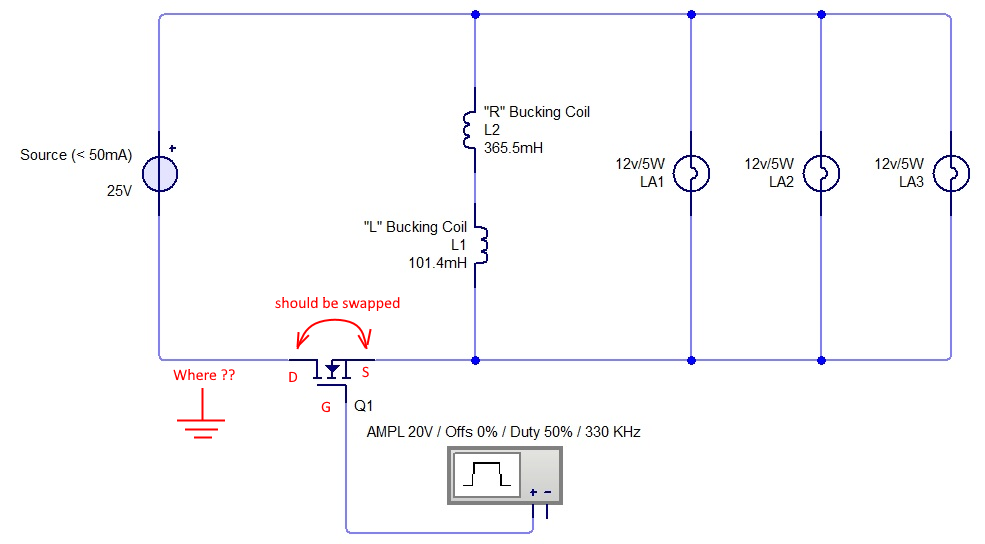
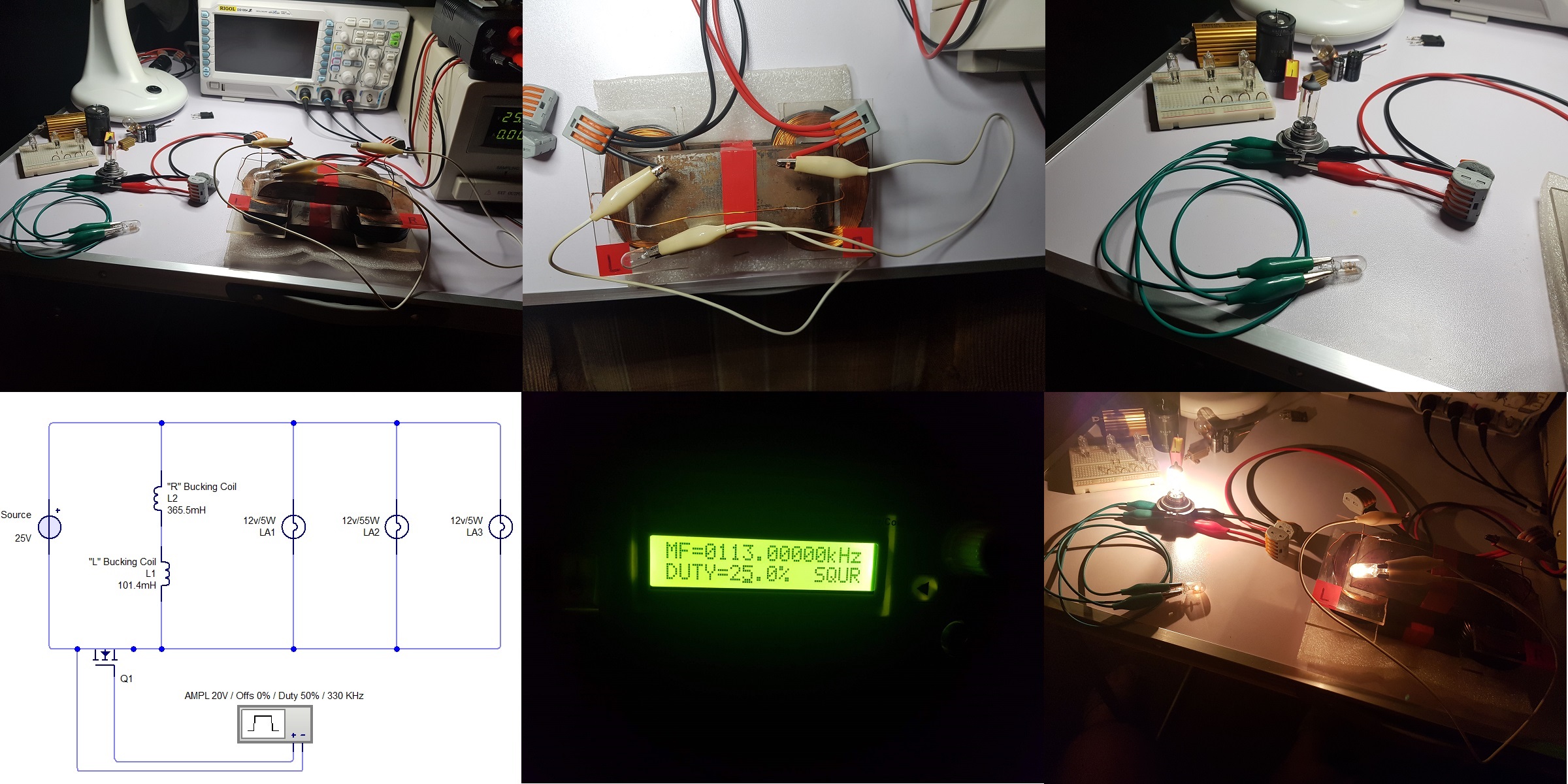
And here is the anomaly I was talking about, basically when placing on the output of the ZPM three light-bulbs (two 12V/5W and one 12V/55W) the device seems to have a preference in how it powers up these light-bulbs.

More specific, the two 12V/5W light-bulbs are connected to the output using identical wires (just different colors - white and green) but their luminosity is different depending on their order. Basically the luminosity of the 12V/5W light-bulb placed after the 12V/55W light-bulb is much lower than the luminosity of a identical light-bulb placed before the 12V/55W light-bulb.

In the following images you can see details. As I said I was looking for a conventional explanation but didn't found one for the device's preference but I find it very intriguing:

And Vidura's confirmation post is here:

https://www.aboveunity.com/thread/romanian-zpm-zero-point-module/?order=all#comment-bee66be5-e5d4-46f5-be19-aaa20010fec2

More specific:

Hey Fighter and all, The effect that the light bulbs on different connected points (or different wire length) have unequal luminosity is a sign for standing waves at high frequencies. Comparable with Tesla's experience when he shorted a transmission line at one point with a thick copper bar and had at another point of the line light bulbs lit.

And I'm sure he's right, according to my (limited) knowledge of the official physics different voltages present in two wires should be present only on very long wires. Which is not the case here as the two wires on ZPM's output are very short and the different voltages seems to be present in some kind of nodes on the output wires.

About finding QJ6005E DC source for replicating ZPM, I checked and I found some on Ebay (first Google search result) but I think that would be an too expensive approach...

https://www.ebay.com/itm/263185946677

What I tried at that time was to find the electronic schema of my DC source but no matter how sofisticated my search queries were I didn't found any. Maybe the things have changed in the meanwhile and could help in avoiding the expensive approach. Knowing the exact circuitry on the DC source maybe could help in having an idea what we're dealing with and if there is anything there working in resonance with ZPM.

I'll try to search again tomorrow for the electronic schema when I have a break from work, maybe now there is one somewhere.

Regards,

Fighter

"If you want to find the secrets of the universe, think in terms of energy, frequency and vibration."
Nikola Tesla
Fighter posted this 08 November 2022

Found some kind of clone of my DC source:

https://www.aktakom.com/products/index.php?SECTION_ID=493&ELEMENT_ID=30290

I wonder if the components and schematics are identical.

If yes then maybe there are schematics for this one ?

I'll try to find more tomorrow.

Regards,

Fighter

"If you want to find the secrets of the universe, think in terms of energy, frequency and vibration."
Nikola Tesla
  • Liked by
  • Inception
  • Atti
Itsu posted this 08 November 2022

Replying To: Vidura

Vidura,

Thanks for the info on the PS, most have the same design, but there are differences as my 3 PS's all behave differently when attached (without the outside filter) to the ZPM.

By the way, i miss the link to the RLC calculator 😀

Itsu


Vidura posted this 08 November 2022

Sorry, I didn't paste the link: http://www.stades.co.uk/RLC%20filters/RLC%20LPF.html

Vidura

  • Liked by
  • Fighter
  • Inception
Itsu posted this 08 November 2022

Replying To: Fighter


Fighter,

don't worry about trying to assist, we know you are wanting to help as much as possible, but don't let it stand in the way of your work and other duties.
There are some knowledgeable guys here who when joined together should be able to determine what is going on.

I also found some data on your PS including that clone, but up till now no schematics found of it.
The ebay offer looks the right model, but including the shipping costs would make it an expensive action to take.

I am experimenting with your setup and will present some measurement data and video's so hopefully we find something interesting.

Thanks for the info,   Itsu

Fighter posted this 08 November 2022

Replying To: Itsu

Thank you.

Yes, I'm also proud of our team here, we have very knowledgeable and experienced members, everytime I have some questions I always ask them and I fully trust their expertise. ☺️

We have here the entire core team of researchers from the old aboveunity site and me and Cd_Sharp are glad to offer all the modern tools and technologies for sharing and exchanging data and experiments in our new site/home.

The site still have some minor issues (mostly user-interface things) which need to be resolved but they are not affecting the functionality in any way and we implemented features, a more intuitive/interactive interface and performance improvements wich makes our site superior to the old site in speed, interface and engine performance.

About the DC source from Ebay, yes, it's too expensive to aquire it just for ZPM replication, there must be other more convenient way.

Regards,

Fighter

"If you want to find the secrets of the universe, think in terms of energy, frequency and vibration."
Nikola Tesla
  • Liked by
  • Atti
  • Inception
Atti posted this 08 November 2022

Hello Itsu!

All right. As I said. I don't have exactly the same part (ACC 200 or power supply with exact parameters)
But to the best of my ability, I tried a few things based on the suggestions.
So I was looking for the effect.
- No. My current did not drop completely to 0 mA.
- The filter (of which I showed a photo) is only an illustration! I'll show you why.
Please take a look from 7:00 am visible.

So even though there is a diode and a buffer capacitor, the disturbing signal is there. At 0:12 you can see that the direction of the current is decreasing. Also visible at 0:54 is a vibration.

This is already captured and buffered by the filter. But the effect is the point. (yes, the filter is home-made. The linear laboratory power supply is also home-made. Unfortunately, there were several cases where a circuit was destroyed due to the returning higher voltage. I did not use a filter circuit then. Such a home-made power supply can be easily repaired, and I already know the components.)


Fighter and Vidura wrote about the length of the wires:

Hey Fighter and all, The effect that the light bulbs on different connected points (or different wire length) have unequal luminosity is a sign for standing waves at high frequencies. Comparable with Tesla's experience when he shorted a transmission line at one point with a thick copper bar and had at another point of the line light bulbs lit.......
And I'm sure he's right, according to my (limited) knowledge of the official physics different voltages present in two wires should be present only on very long wires. Which is not the case here as the two wires on ZPM's output are very short and the different voltages seems to be present in some kind of nodes on the output wires.


In my opinion, we should rather think about the following. It is not certain that what I am saying now will hold its place in the ZPM as well. Because ZPM works at a higher frequency. (or not necessarily, because think about the presented videos)
 But let's consider the following:
- We know the operating principle of photovoltaic network regenerative inverters. Nothing special. The voltage of the inverter is only slightly higher than the mains and the direction of the current is already reversed.
- If an asynchronous motor is increased above the synchronous speed, the direction of the current also changes. The voltage will be in phase and only rise a little.

So it can be seen that "something" plays the role of the generator in ZPM and other arrangements.

The question is:
-What is the "generator" that returns the energy to the voltage of the source?
The material of the iron? The game of the magnetic field? The external influence? The idle energy?

(I apologize to everyone for the examples because it does not belong closely to the ZPM device)

Thank you. Atti.

  • Liked by
  • Fighter
  • Inception
Close