Romanian ZPM (Zero Point Module) - Enhancements Stage

  • 4.1K Views
  • Last Post 28 November 2023
Fighter posted this 13 February 2023

This is the second imported thread (from the old aboveunity site) about my ZPM:


For references I will keep the original posting date for every imported post.

Note: This thread is public, everyone can see it, even the visitors which are not members here.

For the posts made by former aboveunity members which are not members on our site I'll use a member placeholder named UndisclosedMember.

Regards,

Fighter

"If you want to find the secrets of the universe, think in terms of energy, frequency and vibration."
Nikola Tesla
Fighter posted this 18 October 2019

@Vidura I know about their performance, the only issue I had was about those dangerous frequencies after I put these protection diodes, I don't know why it happens but seems ZPM don't like having these diodes on MOSFETs.

For sure I intend to give MOVs a try when I'll have some backup MOSFETs for replacement just in case MOVs create the same behavior.

About the single-wire transmission that was fun to see but still after I saw that phenomenon I wonder how strong and how extended is the electromagnetic field around ZPM and if I should take measures to shield it during experiments. What would be your advice about this, what would you do ?

About the additional LED indicators, I understand they may become active in certain situations so I'll certainly add them to the shunts, even if they don't light up all the time as I kind of expected your idea is neat and very helpful, thanks ! šŸ™‚

@Jagau That's a very nice core ! šŸ™‚ I suppose you will try a ZPM replication ? If so welcome to the club, I'm glad and I'm curious to see how your experiments work, please share them... šŸ™‚

Yes, saturating that core would be kind of difficult, that's one of the special characteristics about Metglas. Being made by Hitachi make me sure your core have exactly the same physical characteristics (related to alloy composition and production process) just like mine because those guys have a strict production and quality control process.

I gathered two quotes from the old ZPM thread which I think could be useful in understanding more about Metglas:

I'm putting links about AMCC-200 technical specs here:

Hitachi - AMCC Cores Technical

Hitachi - AMCC Cores Presentation.

I recommend checking how Metglas cores are produced and read about their special characteristics so you know what you're dealing with; remember Metglas was something produced in 70s for military and space technologies.

Actually this is Metglas - a iron core. Its composition is 85-95% iron, 1-5% boron and 5-10% silicon as specified here. But what's special about this core is it's made of foils created by melting the compositions under high heat then cooling it down so fast (almost instantly) that the Metglas alloy don't have time to form a crystalline atomic structure when it become solid again like any metal does when being melt then being cool down normally. That's why the metals obtained this way are also called amorphous (their atomic structure is not crystalline like the usual metals).

You'll notice the differences about AMCC compared to other cores, enjoy your experiments and can't wait to see it at work ! šŸ™‚

"If you want to find the secrets of the universe, think in terms of energy, frequency and vibration."
Nikola Tesla
Vidura posted this 18 October 2019

Hey Fighter, Note that the SF28 diodes are not TVS devices, and thus can not be considered as protection, if connected in parallel they would only bypass the internal body diode of the MOSFET. But as the internal diode of the cree devices is already very fast, it don't make much sense to place it in that way. I think there was a suggestion to put a diode in SERIES with the MOSFET , to prevent the effect of bus pumping, or current being sent to the supply, which would make more sense. But maybe it is better to test this things with a cheaper MOSFET first, or an IGBT, for a short time would be okay. Regarding the radiation (longitudinal) , there are several reports of being beneficial for health, but this might depend on the frequency also, actually there exists a device based on Tesla oscillators used for cure several diseases, development of a Russian investigator. I have many years worked with Tesla coils and i think i didn't note any negative side effects. But if you like you can anyway use a shielding, or keep some distance for any case. The only thing you should take care is that at the hot end of the coils you might get rf burning if you touch with bare fingers, this effect is stronger with lower frequency, so the core devices can make smoke your fingers in an instant šŸ˜€. Vidura.

Vidura

Fighter posted this 20 October 2019

@Vidura, you mean to put the SF28 between DC source and MOSFET driver on the positive wire ? I remember I tried that with another diode, I admit it was not a super-fast diode. I can try this scenario too, thanks.

About touching the ends of the coils, I was thinking to get some protection gloves for electricity, for safety I'll buy some. Considering there are spikes of 100-200Vpp, at what frequency could that become dangerous ? Right now I don't go below 80 KHz, usually I'm in 100-1770 KHz range.

Posting updates...

I've build a new version of current indicators, this time I added a second LED with inverted polarity so they will show currents going in both directions through the shunts:

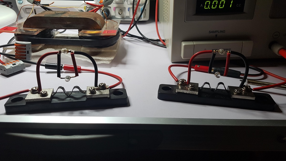
This is a test with normal polarity:

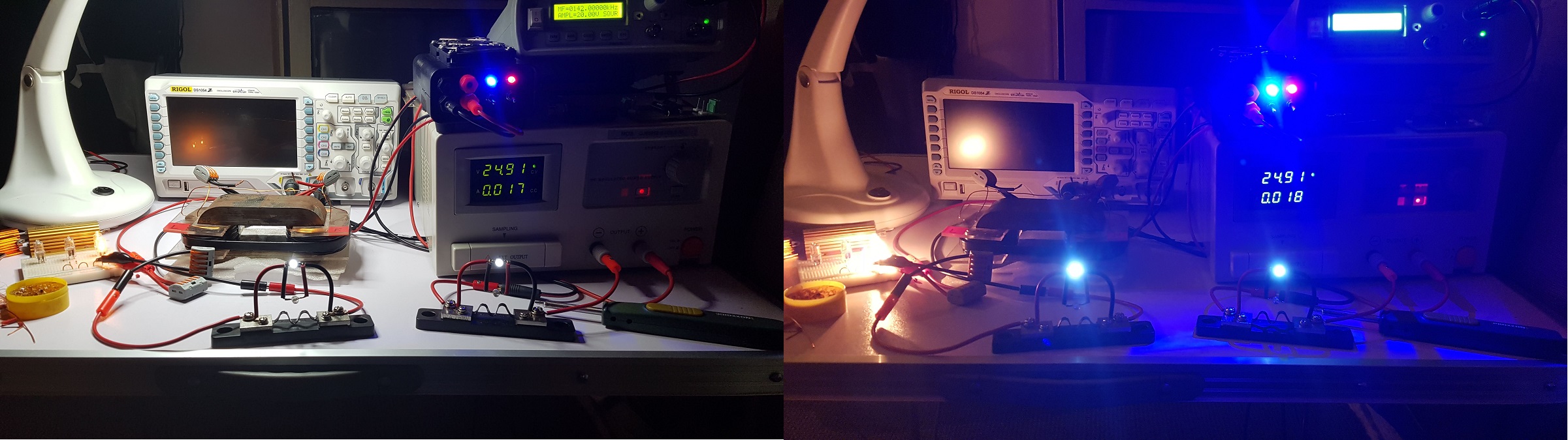
And this is a test with inverted polarity:

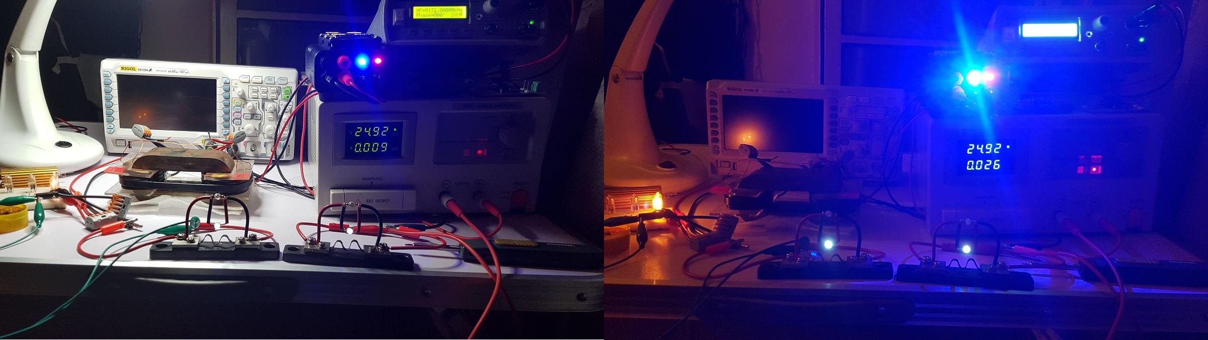
For some reason the LEDs for inverted polarity (positioned lower) don't have the same luminosity even if the current should be the same like with normal polarity. All circuit is made using normal 0.8mm wire (just like the one ZPM's coils are built with) enclosed in plastic. I verified the solderings and found no issue.

But for now it's not that important, I'm interested more in what the upper LEDs are showing.

As a note, the fact that a LED indicator is off doesn't mean there is no current, it means there is not enough current to produce enough voltage to power-up the LED.

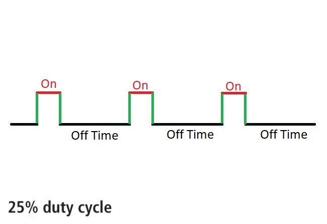
When I find some time again I will try to rectify the pulsed voltage produced by the shunts, meaning this:

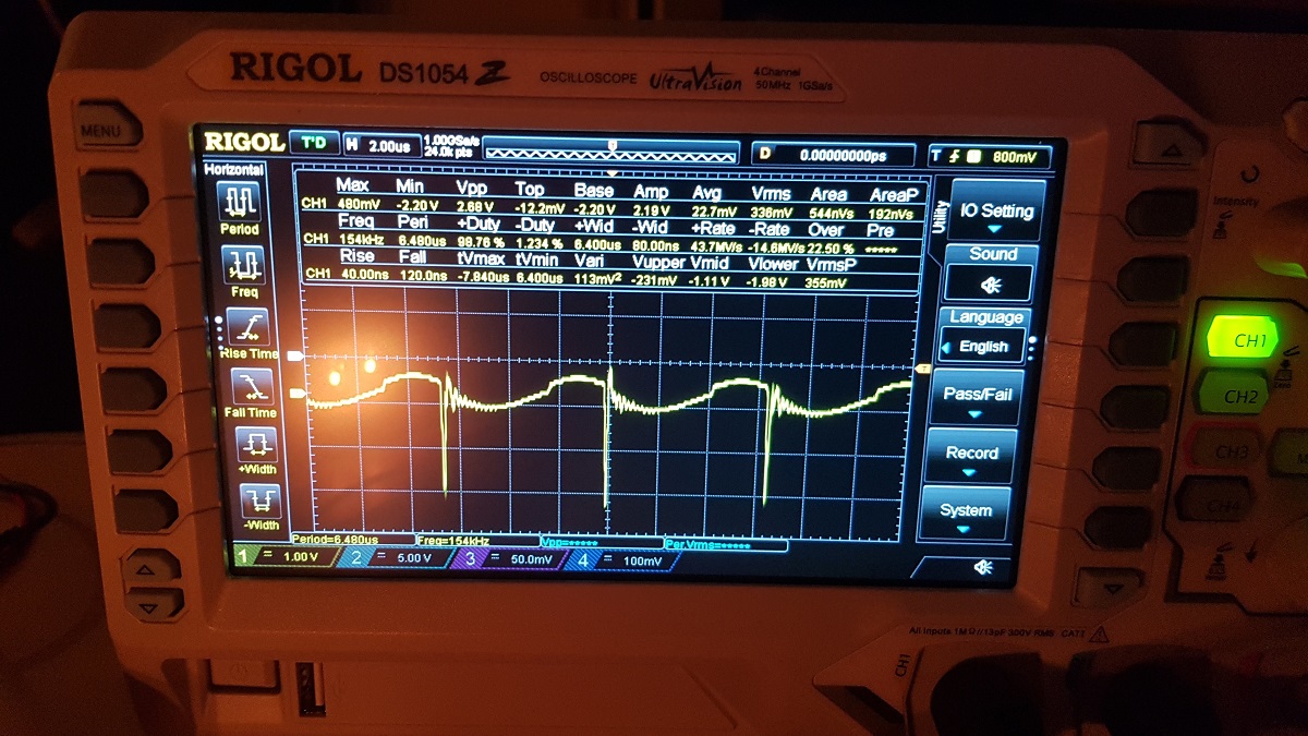
I intend to build a bridge-rectifier using some super-fast SF28 diodes and then some electrolytic capacitor maybe (choosing the right one to smooth that waveform will be difficult, I'll need to do a lot of tests).

If I'll succeed then having pure DC produced by the shunts would mean I can use digital voltmeters to get real-time accurate reads for currents passing through shunts.

"If you want to find the secrets of the universe, think in terms of energy, frequency and vibration."
Nikola Tesla
  • Liked by
  • Wistiti
UndisclosedMember posted this 20 October 2019

About touching the ends of the coils, I was thinking to get some protection gloves for electricity, for safety I'll buy some. Considering there are spikes of 100-200Vpp, at what frequency could that become dangerous ? Right now I don't go below 80 KHz, usually I'm in 100-1770 KHz range.

There is a certain frequency threshold above which your heart muscles cannot respond quickly enough and so alternating currents above that frequency won't stop your heart. Not sure where this frequency is exactly, but I vaguely recall it is between 2k and 4k. Above that frequency you should be fine. Below that, and you are at risk any time you are grounded as your blood vessels may act like conductors and your finger tips would be capacitively connecting you to the circuit. High currents should cause burns at any frequency but these would likely be over your skin at very high frequencies. Not sure what the current threshold is for that.

I worry more about my family when I am doing these experiments. Little ones especially have a way of getting into trouble grabbing things they shouldn't. A family member checking on you after you make a mistake may suffer the same. Precautions are good. Take note if any family member or guest has a pacemaker. Stay safe.

Vidura posted this 20 October 2019

@ Fighter
The Fast diode would be placed between the ZPM and the mosfet better, I am not sure if the current capability of the SF 28 is enough.
About the led indicators of course there is a threshold voltage , it will only lite with considerable current spikes, I have thought about this.
@ Zanzal
regarding the current, generally it is dangerous at low frequency or DC specially, above 30Khz it is considered RF , and the skin effect begins to predominate, so the current will flow on the surface, the RF burning is superficial normally , anyway for safty keep the kids at distance when experimenting with this kind of devices.

VIDURA.

Vidura

Jagau posted this 24 October 2019

Hi fighter
My C core mestglass is progressing well.
I build the insulators in acetate and I prepare to mount the 2 coils.

I have a little technical question to ask you, so with about 150 laps for the primary you have an inductance of 101.4 mh and for the secondary 300 laps with 365 mh on an AMCC200.


What I do not understand if i check inductance factor and with the specifications of the manufacturer (photo below) we have 1.26 uh / N2 for ungap of 0.5 mm.

If I remove the gap we could say that it is about 2 uh / n2
so with 101 mh it would take 200 laps for the primary.
This is the question I am asking.


JL Naudin used an AMCC320 which is like mine and is a little bigger than the 220 and with 24mh he had 100 laps.
Could you tell me if I have the right number of turns?
It does not matter if you do not know I will find.
thank you


Jagau

Fighter posted this 24 October 2019

Hi Jagau,

This is what my LCR meter shown after I built the coils:

It has two bucking coils (marked the with "L" and "R") winded in a way that when they're connected in series and powered on, their magnetic fields are opposing.

L coil has 101.4mH inductance and approx. 150 turns made of 0.8mm standard copper wire for coils. These are the complete characteristics I measured with my LCR meter:

R coil has 365.5mH inductance and approx. 300 turns made of 0.8mm standard copper wire for coils. These are the complete characteristics I measured with my LCR meter:

I ran auto-calibration before making measurements just to make sure. About the number of turns, the counting error is maximum +/- 10 turns (because I've made the coils manually), so yes it's 150/300 turns ratio with maximum +/-10 turns counting error. The gap is displayed in the latest photos, it should be 0mm because I stretched as much as possible that zip tie keeping the pieces together. I would say to follow one of the coil ratios reccomended by YoElMiCrO, ignoring the turns counting error mentioned I consider my ZPM configuration with 150/200 ratio is matching one of them. It's possible that the inductances shown by my LCR meter are because I've made the coils manually and the turns are not ordered as they would be if using a coiling machine, I'm sure the inductance is different between coils made manually and coils made with a machine.

"If you want to find the secrets of the universe, think in terms of energy, frequency and vibration."
Nikola Tesla
Jagau posted this 24 October 2019

Hi fighter
thank you for answering,

I will do my 2 coils and see how they behave

Jagau

UndisclosedMember posted this 24 October 2019

My Friends,

If I may interject here for a minute.

Fighters Coils are: 1 : 2 basically, as YoElMiCrO kindly pointed out:

N2 = sqrt(n) * N1 = sqrt(0.25) * 300 = 150 

Which is Fighters Coil Combination!

We have a situation here, where Fighter is using 25% Duty Cycle on the Input:

What occurs during all that Off Time?

No one is looking at this???

This 25% Duty Cycle is the same as the 0.25, the Quarter Wave. 25% Duty Cycle is a Quarter Wave, they are the same thing! This is important, please, something people need to start thinking about.

cd_sharp posted this 25 October 2019

The sqrt(0.25) is a measure of the time constants ( t ) difference between the coils. 5 time constants is a number which defines the time needed for the current to reach max value which is equivalent to max magnetic field.

If you know how to build such a device and you're not sharing, you're a schmuck! - Graham Gunderson

Close