Hey Cd_Sharp, thanks. No worries about your opinion, the idea is I think it should be a required step in this stage of enhancing ZPM having real-time input and output accurate readings, else I would go in blind during enhancement experiments and I wouldn't know if I'm going in the right direction or in the wrong direction.
Unfortunately after the last testings I'm not sure about the accuracy of this method of measuring input as it doesn't match the measurements made on oscilloscope, I'm adding the previously made oscilloscope measurements here for reference:
Hey Fighter,
You have my Vote!
Purely Resistive Load, no phase angle to worry about! Figures look good!
Input:
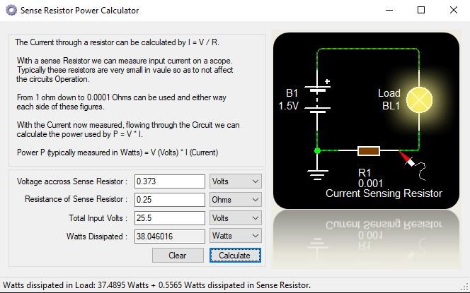
Output:

Well done! Good work Fighter!
You have "Generated" a full: 3.574784 Watts above your Input for a COP: 1.09396
and also because this customized DC source I made seems to modify the behavior of the ZPM.
I'll present the data of the latest experiments.
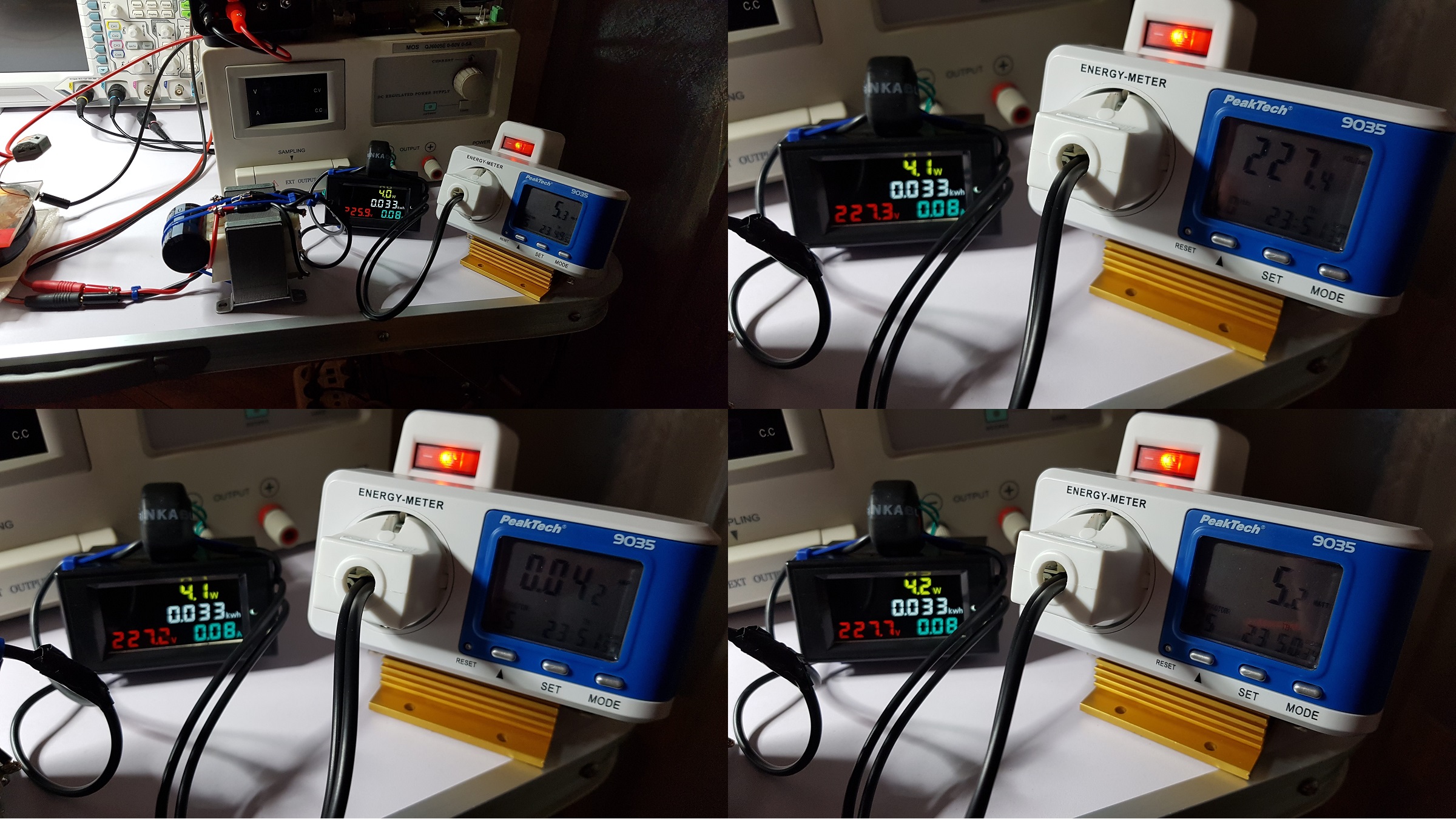
The customized DC source plus the measurements module are consuming about 5.3 watts.
Basically the customized DC source is consuming about 4.1 W and the measurement module about 1.2 W.
Sorry but the PeakTech energy-meter don't have display light but in the next photos is shows 227.4 V, 0.042 A, 5.2 W.
Photos:
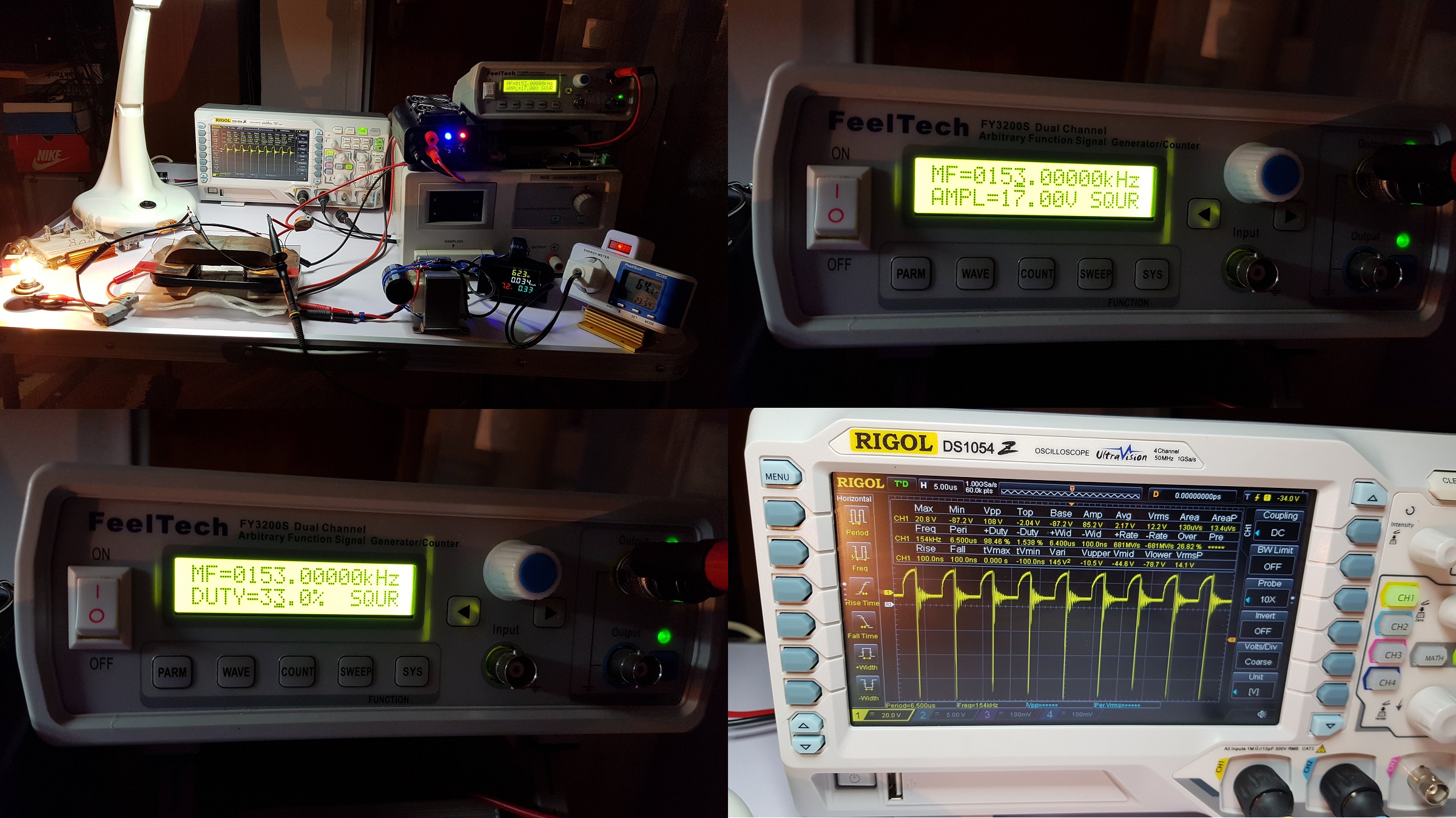
In the next photos I show ZPM powered by the customized DC source where the probe of the oscilloscope is put directly on ZPM's output:
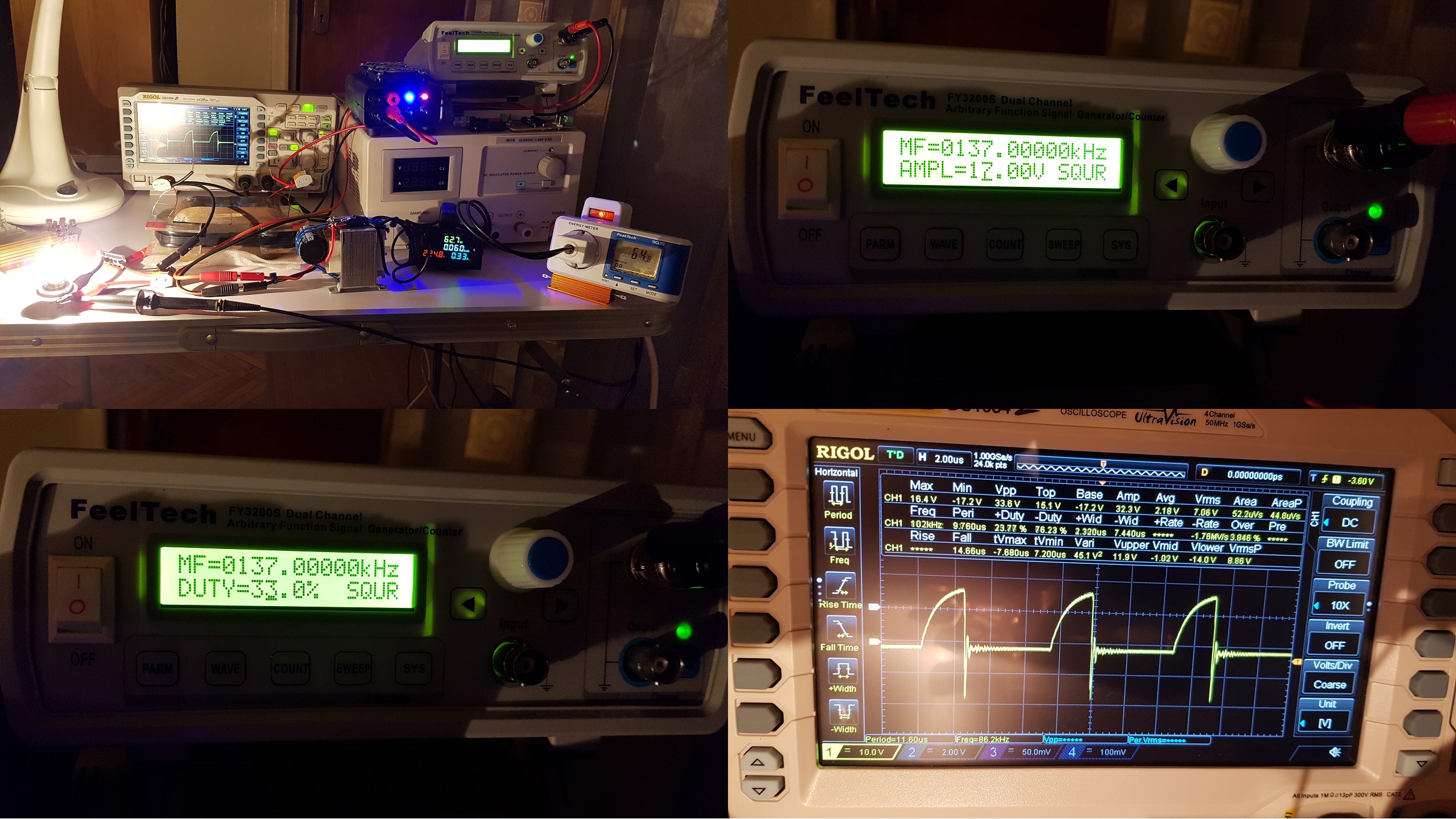
As you can see the measurement module shows 62.7 W, much more than the 38.04 W previously measured using the oscilloscope. Also you may notice the ZPM's specific waveform is not present, I don't recognize this waveform and it means ZPM's behavior is changed.
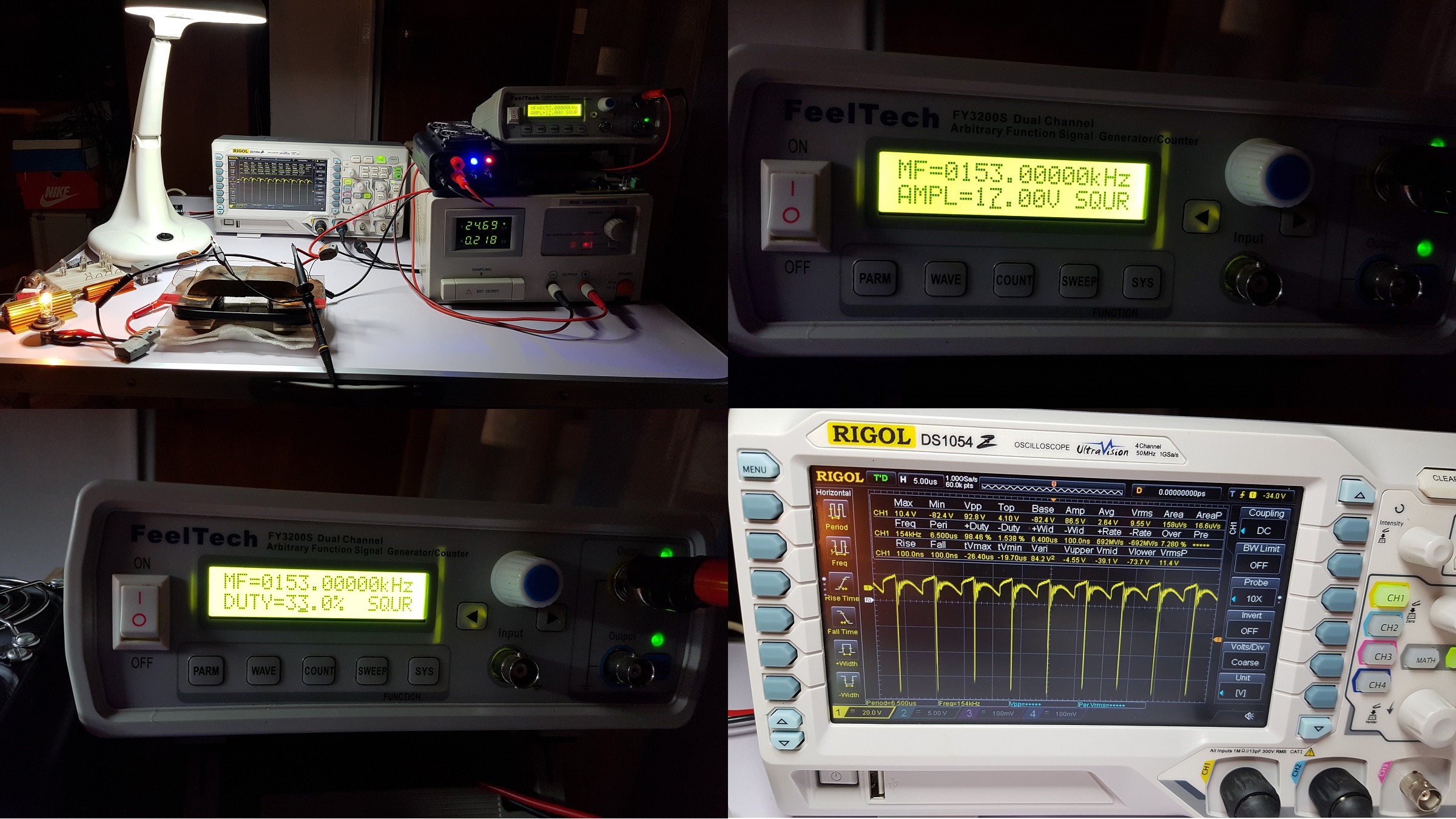
In the next photos I'm using exactly the same parameters I just switched to my usual DC source:
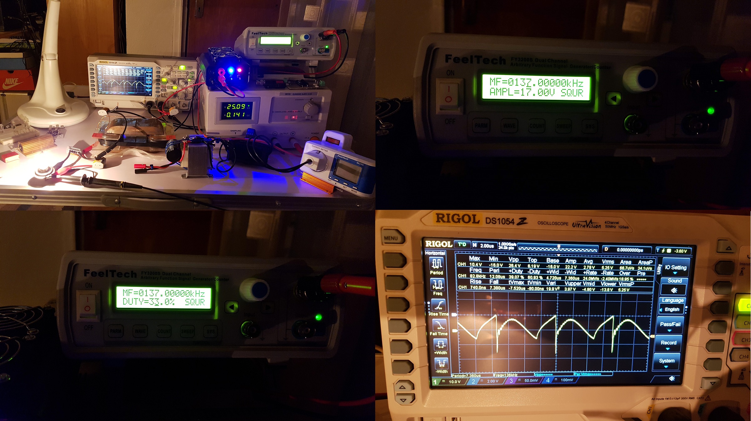
You may see the ZPM specific waveform is present again now.
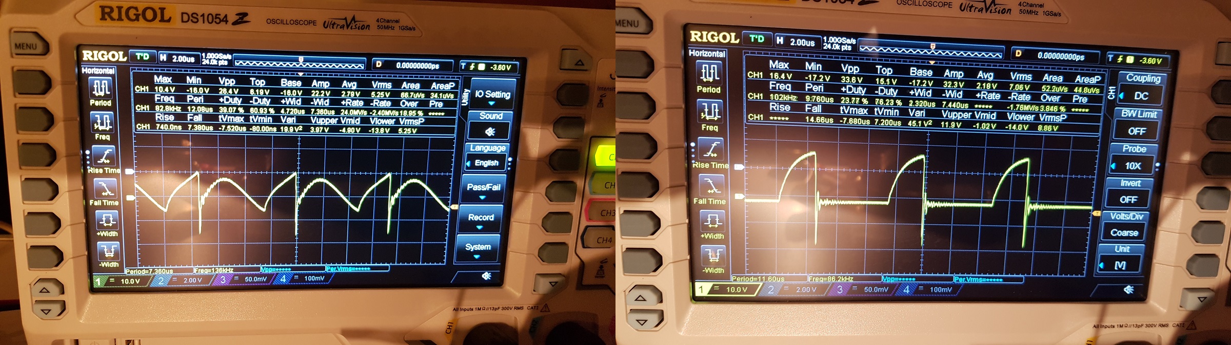
In the next image you may see the different behavior when using both DC sources, on the left is the waveform when using my usual DC source (ZPM pattern is present) and on the right when using the customized DC source:
Then I placed oscilloscope's probe directly on the light bulb pins and searched for another optimum frequency and repeated the tests (with the customized DC source then with the usual DC source).
These are the images made while using the customized DC source:
And these are the images made while using the usual DC source:
As you may see it's the same changed behavior, the ZPM's specific waveform is present when using the usual DC source and it's not present when using the customized DC source.
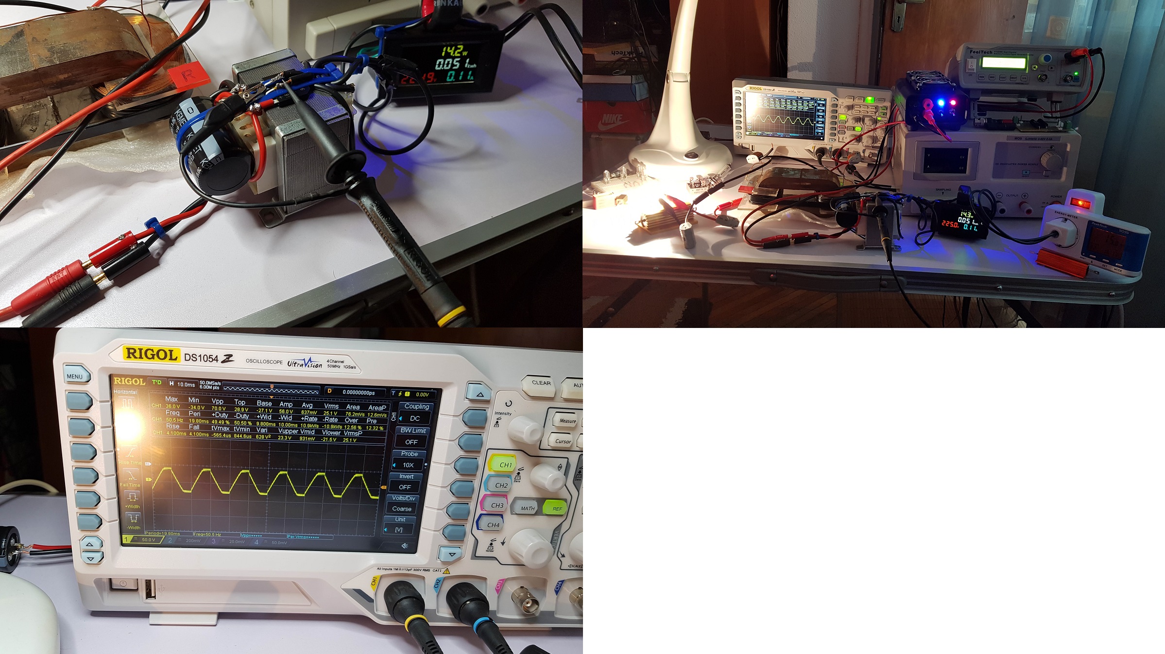
For curiosity I wanted to see what's between the transformer and the bridge rectifier, this is what I see on oscilloscope:
As a conclusion I consider this way of real-time measuring of input a failure as it's far away from what the oscilloscope shown and also the customized DC source is modifying ZPM's behavior. Seems there is something in the usual DC source and that something is missing from my customized DC source.
Also I was thinking of other possible reasons for failure. The bridge rectifier is made for 50Hz and as we know ZPM is sending high-frequency pulsed power back which for sure rectifier's diodes are unable to block/handle. Probably that power is reaching transformer's secondary and creating magnetic field which is fighting the magnetic field of the transformer's primary. That would be a possible explanation for what the extra-watts shown by the meters.
This hypothesis may be confirmed by the fact that the bridge rectifier and transformer's core are getting hot in about 10 minutes which is strange because the transformer is rated for 1.5 A but during the tests the current used is just 0.33 A. At 0.33 A both transformer and bridge rectifier should not get that hot and that fast.
I suppose another approach is needed for real-time measurements and also I wonder what exactly is in the usual DC source and is missing in the customized DC source making ZPM to change behavior when using the customized DC source. Many new questions and hypothesis resulted from these new experiments even if they failed, I'll think about them.
As usually any suggestions are welcome... 🙂
| "If you want to find the secrets of the universe, think in terms of
energy, frequency and
vibration." |
|
|
Nikola Tesla |


