Romanian ZPM (Zero Point Module) - Enhancements Stage

  • 4.1K Views
  • Last Post 28 November 2023
Fighter posted this 13 February 2023

This is the second imported thread (from the old aboveunity site) about my ZPM:


For references I will keep the original posting date for every imported post.

Note: This thread is public, everyone can see it, even the visitors which are not members here.

For the posts made by former aboveunity members which are not members on our site I'll use a member placeholder named UndisclosedMember.

Regards,

Fighter

"If you want to find the secrets of the universe, think in terms of energy, frequency and vibration."
Nikola Tesla
Fighter posted this 22 December 2019

Hi UndisclosedMember, the meters are put before the custom DC source, they are actually measuring 220V/50Hz input. But I agree there is something wrong with the readings, I'm still organizing and adding data to the previous post, I'll explain and add a conclusion.

"If you want to find the secrets of the universe, think in terms of energy, frequency and vibration."
Nikola Tesla
Fighter posted this 22 December 2019

I just saw your latest edits, UndisclosedMember, you're right, there are too many flaws in this approach. Most of the components are made for 50 Hz and can't handle/block high-frequencies. I was hoping that by moving the measurements block before the transformer and measuring 220V/50Hz I will escape from the high-frequency power sent back by ZPM. Seems it's not the case unless I use a bridge rectifier which can handle/block high-frequency power coming against it. Also there seems to be some component in the DC source which is missing in my customized DC source and that missing component is the cause of ZPM's changed behavior. Many things to think about but also some lessons learned... 🙂

Edit: A battery could be a good idea, don't know if there are some ~25V batteries, maybe rechargeable so I avoid significant costs for each experiment. But it's possible that a battery could modify ZPM's behavior too if there is "something" in my usual DC source which is actually actively working with ZPM to behave this way. That "something" needs clarification: does it exist and if yes what component is it ?

"If you want to find the secrets of the universe, think in terms of energy, frequency and vibration."
Nikola Tesla
UndisclosedMember posted this 22 December 2019

My Friend, I agree!

A reason a forum, to share our experiences is so important, a documentation archive that will serve humanity for decades to come!

There is always more to learn! We humans think we know everything, in general, but the truth is, there is more to learn than what we have already learnt!

The humans that can memorise entire physics volumes, is nothing compared to a life time of real world experience.

My friend, this is invaluable knowledge for others!

EDIT:

Edit: A battery could be a good idea, don't know if there are some ~25V batteries, maybe rechargeable so I avoid significant costs for each experiment. But it's possible that a battery could modify ZPM's behavior too if there is "something" in my usual DC source which is actually actively working with ZPM to behave this way. That "something" needs clarification: does it exist and if yes what component is it ?

Yes, agreed. However, a Battery will serve as a better reference point as to the Actions / Reactions that occur with the ZPM than a DC Power supply as it has no Circuitry. High Frequency DC Pulses will be absorbed, Charge the Battery, much better than random Circuitry that exists in a DC Power Source. I was thinking about 2 x 12V 7Ah or similar Rechargeable Batteries as a possibility?

Fighter posted this 22 December 2019

Thank you UndisclosedMember, I'll take into consideration this approach.

"If you want to find the secrets of the universe, think in terms of energy, frequency and vibration."
Nikola Tesla
Vidura posted this 23 December 2019

Hey Friends, Recently I made some tests related to noise , and found that there is some kind of it which is virtually impossible to filter or screen out. That the high frequency current passes thru a steel core transformer and interfere the digital instruments is not surprising at all. Also it is possible that a lot of power is dissipated in the low frequency rectifier. Regarding the change of the wave form of the ZPM when using the simple transformer, could it be a voltage drop the cause? There might be a threshold voltage for the ZPM to perform properly.As the lab PS is voltage stabilized, it is supposed to maintain the selected voltage, no so a standard transformer, there can be major variation depending on the load conditions. I agree that a battery would give valuable comparison. If it is actually some circuitry inside the PS that is interactive , it should be possible to find which components. Some time ago I had an issue with my PS , the current limiting was damaged, so I opened it to check, it is of the analogue type, a multi tapped steel core transformer, and linear voltage regulation, not switch mode type. I was a bit surprised about the few components on the output line, a single electrolytic capacitor , a precision current shunt, and a few more components. The only digital components are the voltage and current meters. I guess the Switch mode type PS has more filter components , to keep the switching noise low. But if Fighters PS is the analogue type, there are only a few possibilities of interacting components. By the way, I got a notice from costumes about a packet, this could be the metglass core, hopefully, now nearly four months ago was shipped from Europe. So maybe soon I can join the testing of the ZPM. Vidura.

Vidura

UndisclosedMember posted this 23 December 2019

Hey Vidura,

Re:

If it is actually some circuitry inside the PS that is interactive , it should be possible to find which components.

I agree! and this could be assistive of course in our furthering the overall understanding of Input Power and the reasons it can sometimes behave differently.

Four months, wow, that's a slow delivery, sounds like Australia Post! Our postal service is very slow also depending on what country the source is coming from!

I think you will find the Metglas Core very useful!

Fighter posted this 23 December 2019

@Vidura

Hey Friends, Recently I made some tests related to noise , and found that there is some kind of it which is virtually impossible to filter or screen out.

So filtering the noise sent back by ZPM is impossible...

Also it is possible that a lot of power is dissipated in the low frequency rectifier.

This seems to be the case, the bridge rectifier and/or the transfomer become hot in about 10 minutes so those extra ~30W consumption shown by energy meters most probably are dissipated in that heat.

Regarding the change of the wave form of the ZPM when using the simple transformer, could it be a voltage drop the cause? There might be a threshold voltage for the ZPM to perform properly.As the lab PS is voltage stabilized, it is supposed to maintain the selected voltage, no so a standard transformer, there can be major variation depending on the load conditions.

This could be the case of voltage drop. I could make a test with the usual DC source by setting the voltage much below 25V and check how the waveform looks like.

I agree that a battery would give valuable comparison.

I will try this way, I will look for some local supliers for rechargable battery/batteries.

If it is actually some circuitry inside the PS that is interactive , it should be possible to find which components. Some time ago I had an issue with my PS , the current limiting was damaged, so I opened it to check, it is of the analogue type, a multi tapped steel core transformer, and linear voltage regulation, not switch mode type. I was a bit surprised about the few components on the output line, a single electrolytic capacitor , a precision current shunt, and a few more components. The only digital components are the voltage and current meters. I guess the Switch mode type PS has more filter components , to keep the switching noise low. But if Fighters PS is the analogue type, there are only a few possibilities of interacting components.

My DC source is switch-type, I remember I chosen it specifically to be this way, that's why is has about 16kg weight. The model is QJ6005E and the manufacturer's page is here:

http://www.nbjiuyuan.cn/Single-output/products_21_en.html

Unfortunately there are no schematics anywhere on internet but I found a image from inside:

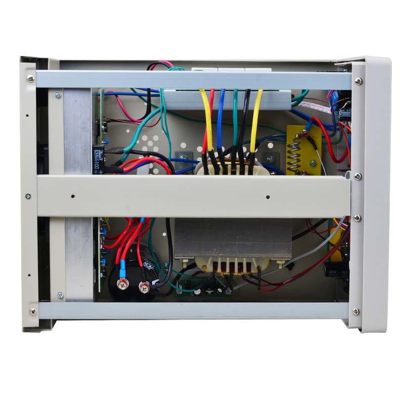
I see that big current-sensing shunt and also I see there are a lot of electronics, some of them could possibly actively working with ZPM but I have no idea which one.

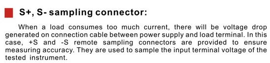
On the manufacturer's site I see this option but it's for measurements when voltage drop occurs, I don't think it will help with high frequency noise:

By the way, I got a notice from costumes about a packet, this could be the metglass core, hopefully, now nearly four months ago was shipped from Europe. So maybe soon I can join the testing of the ZPM.

I would be glad if you could join the ZPM research, having another ZPM in experiments with different power source and measuring instruments will be very helpful in clarifying some aspects and ZPM's behavior !

@Atti

This is just an opinion, not to be accepted but to consider.
In my opinion, the load on the transformer of a single DC source is probably too close to the maximum load. (36 VA)
Therefore, the peak current draws too much down the buffer capacitor voltage. Whirring tension.
Therefore, the input waveform on the secondary side of the individual transformer.
If you could replace it with a larger transformer (maybe 200VA)
waviness would decrease.

Another solution could be to use L-C filters before the ZPM input.

I agree, the voltage drop could be the reason for ZPM's behavior change, I'm taking this into consideration. I could try a test with the usual DC source but setting the voltage much lower than 25V and see how the waveform looks like. About filtering out the high-frequency noise sent back by ZPM, seems it's not a possible solution according to Vidura, seems this is a particular situation where filters don't work. I remember I tried with a choke coil on input and ZPM don't like that, I had extensive damage: DC source entered in auto-protection mode, the light bulbs on output burned and also the MOSFET was destroyed.

If you are using a factory lab power supply, then its wiring diagram would be good to know.

Unfortunately I could not find any schematics on internet for my DC source. You may find more details in my previous replies to Vidura.

"If you want to find the secrets of the universe, think in terms of energy, frequency and vibration."
Nikola Tesla
Vidura posted this 23 December 2019

Hey Fighter and all following, I don't know if it's really impossible to filter that interference, but I can assure that it's not an easy task, I have tried with common mode choke, differential mode choke, different types of R C L filters, but the interference in the digital instruments continued, specially with the parametric oscillator circuit and HVTesla coils. The analogue meters seems to remain unaffected. And yes it can be very tricky to make accurate measurements with this kind of devices, but anyway we don't need so much accuracy, If we have a reference to work with it will be helpful to make improvements and monitoring the situation, no need for ten digits below the comma. The PS you have is very similar to mine, this is the transformer type with linear voltage regulation. It is not a Switch mode supply, this refers to high frequency converters with small ferrite cores. The components immediately on the output are the rectifier, electrolytic capacitors and the current shunt (a spiral of copper wire) , and the connectors for the sensing electronics. I had an experience when a interference affected the sensing electronics and the voltage regulation failed, the supply delivered 50V instead of the rated maximum of 30v. Regarding the Battery I would suggest the lead acid batteries, they are tougher for withstand transients, high frequency components and so. The lion batteries might fail in this condition.

Hopefully this helps some. Vidura

Vidura

UndisclosedMember posted this 24 December 2019

My Friends,

I see a lot more confusion entering at the moment than is necessary! There is no need for any complexity!

I am not going to fill Fighters thread with partially off topic content, instead, I am posting a response here.

Realistically you do not want to use any High pass or Low pass Filters when doing measurements! not unless your'e looking for anything specifically! So this talk of filtering and so on is distracting and confusing. 

Like I said:

P.S: Sorry, I see your edits, I edited also. You have a good point, we should start looking at the Input Power Circuitry also. A Battery might be a good choice for a Source as it contains no Circuitry as such?

I think it is only logical to keep this as simple as possible, no point introducing complications when none exist!

Fighter posted this 08 January 2020

Hi UndisclosedMember, I just want to say I saw again the Non-Inductive Coil Experiment videos and a lot of things became much clearer now.

The fact that before I watched them in the evenings after finishing work didn't helped in really understanding them.

Now using this short vacation I watched them again one after one with fresh mind without being tired from work and everything makes sense and I understood a lot. For example I understand now why the input coil must have fewer turns and the wire must be thick, I understand why the duty cycle must be as lower as possible while the secondary (bucking) coils are still interacting correctly, I also have a fresh perspective on ZPM's behavior, actually (as Cd_Sharp told me in a conversation) the "R" coil of ZPM is composed from two virtual coils even if physically is just one coil: a virtual coil is perfectly equal with the "L" coil and it's opposing perfectly to "L" coil while a second virtual coil is actually the input coil and has 150 turns (too many). But unlike your device my (virtual) input coil is connected to one of the secondary coils. That's the reason why the behavior of ZPM is different from the behavior of your device even if they're actually using the same principle of the bucking coils.

So I recommend to all the members to find time when they have fresh mind, few hours available and when they're not tired (from work) and watch all the videos one by one carefully and they'll understand a lot about the interactions between bucking coils, why they behave like that and how to improve the interactions and where to look at during the improvements.

I intend to join the replication of your device as it can help me in understanding better ZPM and help with the improvements for ZPM. As I don't intend to dismantle ZPM (it's the only prototype, as far as I know there are no replicas yet) I think I will buy another AMCC-200 and start working on a replication of your device. Will take some time to receive the core and to design and order different coil supports to a CNC company but I think it's worth the effort. Who knows, maybe during the research we can make a better device, a hybrid getting the best things from your device and from my device.

EDIT: I definitely need to see the videos again as I'm sure there are still details which I missed. I downloaded the videos with the original resolution and I'm adding them to my archive so just in case if you ever need them just let me know, you have also a backup of the videos here.

"If you want to find the secrets of the universe, think in terms of energy, frequency and vibration."
Nikola Tesla
Close