Romanian ZPM (Zero Point Module) - Enhancements Stage

  • 4.1K Views
  • Last Post 28 November 2023
Fighter posted this 13 February 2023

This is the second imported thread (from the old aboveunity site) about my ZPM:


For references I will keep the original posting date for every imported post.

Note: This thread is public, everyone can see it, even the visitors which are not members here.

For the posts made by former aboveunity members which are not members on our site I'll use a member placeholder named UndisclosedMember.

Regards,

Fighter

"If you want to find the secrets of the universe, think in terms of energy, frequency and vibration."
Nikola Tesla
UndisclosedMember posted this 25 October 2019

Hey CD,

The Coils reach maximum Current ( I ) when five time constants have passed.

The equation is: T = L / R

  • T is five Time Constants and is measured in seconds
  • L is the Inductance and is measured in Henrys
  • R is the total circuit Resistance and is measured in Ohms.
     

So no, not really correct, as the coils become resonant, yes we do get maximum Amplitude, but this cant always be assumed this is maximum Current ( I ) for the applied Voltage ( V ).

Resonance, especially this type of Resonance, is quite different. Magnetic Resonance.

cd_sharp posted this 25 October 2019

Hey, man

During the off-time, assuming both coils are charged, they will decay. L2 will try to decay twice faster than L1. That is a changing magnetic field ahead of the changing magnetic field of L1. This results in delayed EM induction in L1, as we named it counter-reaction and it's adding up to the decaying field of L1.

Please correct me if I'm wrong.

If you know how to build such a device and you're not sharing, you're a schmuck! - Graham Gunderson

UndisclosedMember posted this 25 October 2019

Hey CD,

Ah ha, yes you're right!

The Interactions between the Coils.

In Fighters ZPM we see a very interesting Spike:

Marked in Red is the process I describe above in the video. The Coils are like a spring, and Act and React together in Magnetic Resonance. This is an Electromagnetic Induction dance, or disco. Electrons are getting some moves on and the Disco is going off...

This is excess Electromagnetic Induction after the fact! After the Input has excited the Coils into this Resonance.

cd_sharp posted this 25 October 2019

I wish to go further with my imagination. While L1 is discharging slowly, the voltage over L1 is not what it's supposed to be if L1 was discharging alone. The voltage induced by the L2 collapsing adds up to the voltage over the ends of L1 and it causes a much faster discharge (almost instant) than normally. We have increased V, we obtained increased I.

This almost instant collapsing of L1 causes EM induction in L2 and so they start to dance as you said. This device uses the Reduced Impedance Effect so visibly. I look forward to playing, I'm waiting for some hardware..

If you know how to build such a device and you're not sharing, you're a schmuck! - Graham Gunderson

Fighter posted this 25 October 2019

Talking about hardware, some updates on my side, I just received the shipment with 6x12V/55W light-bulbs:

... and I have a shipment with 6 x Cree MOSFETs which is still on the way. This time I bought the MOSFETs from TME, they are more expensive comparing to Digi-Key but as TME is in EU I'll avoid the tax for shipments coming from outside of EU which is signifiant.

So my backup stock will be restored soon and I'll have replacements available again for experimenting.

"If you want to find the secrets of the universe, think in terms of energy, frequency and vibration."
Nikola Tesla
Jagau posted this 31 October 2019

hey fighter

slowly but surely
My acrylic supports are made
and I found (maybe a way to make coils more symmetrical)
I tried to make this coil winder


Jagau

Fighter posted this 01 November 2019

Hi guys, unfortunately I need to take a break from researching because I need to relocate. I will find another place to rent (the owner of this one wants to sell it), pack all my stuff and transport it there. As you can imagine this will take a while and during this process I will not be able to do experiments. I will resume the research as soon as it's possible. Sorry about this but this is how life is sometimes.

Please continue your research, I'll still be here but I will not be able to present anything new until I resolve this problem.

"If you want to find the secrets of the universe, think in terms of energy, frequency and vibration."
Nikola Tesla
UndisclosedMember posted this 01 November 2019

@Fighter

Good luck with your move, I hope it all goes smoothly!

Fighter posted this 20 December 2019

Hi guys, sorry, moving to the new place and setting things up took much longer than I expected.

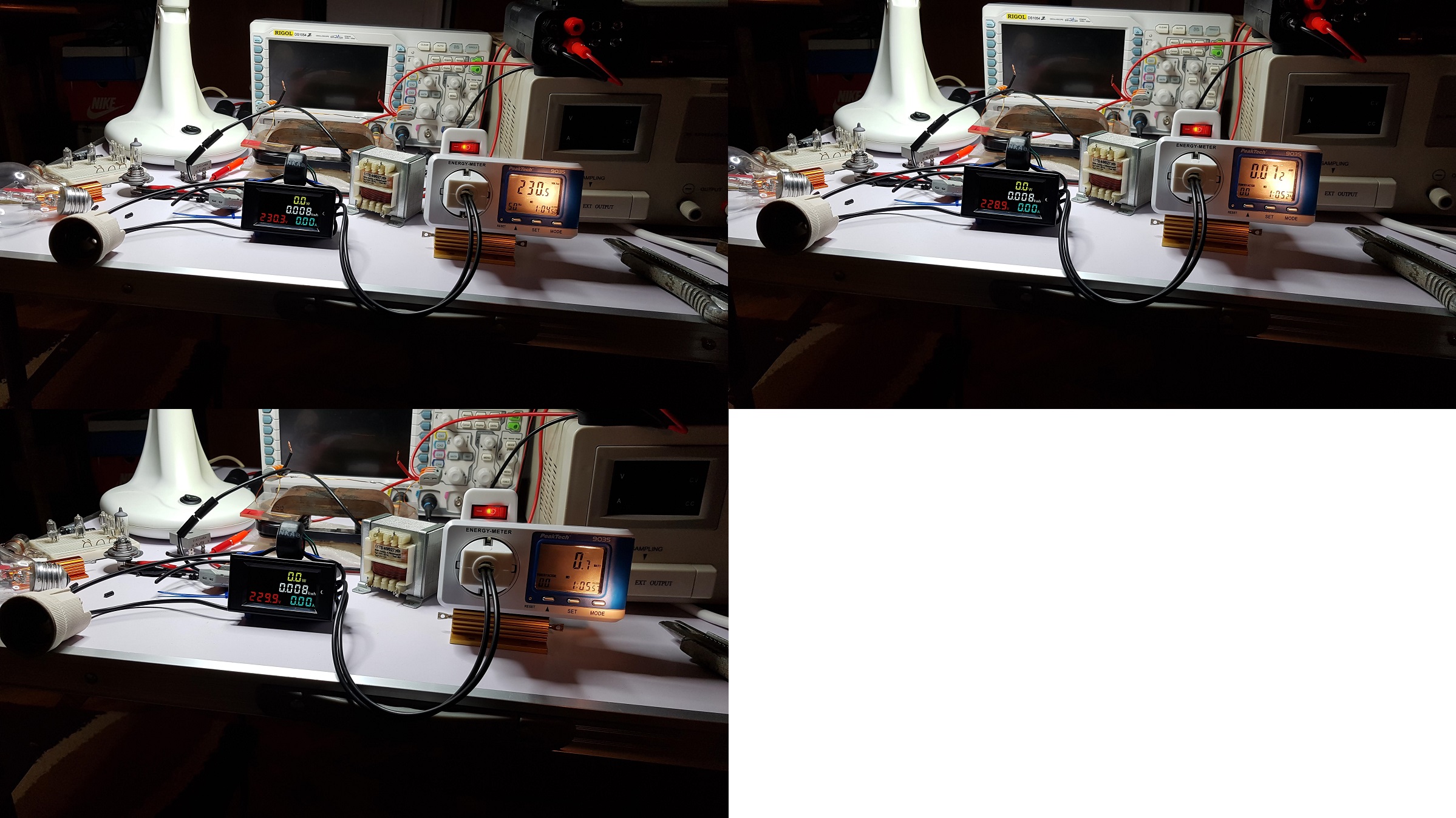
I just received a shipment from China and I'm currently working on a custom DC source where I can have real-time and (hopefully) accurate readings of input. The real-time measurement module is this one. For calibration I'm using a PeakTech 9035 energy meter which is using power factor for very precise readings and calculation. The measurement module seems pretty accurate and it's consuming about 0.6 - 0.7 watts. A few images without load:

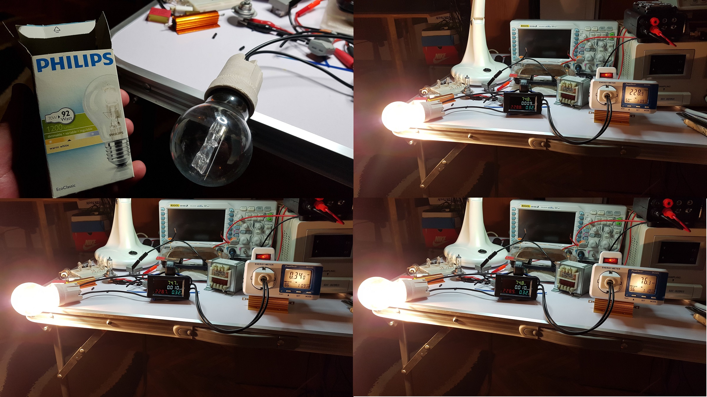
And few images with a light bulb as load:

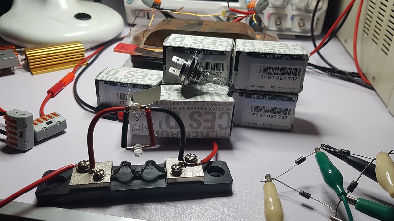
As a custom DC source I'm gonna use a 24V/1.5A transformer, a bridge rectifier and a 10000uF/50V electrolytic capacitor:

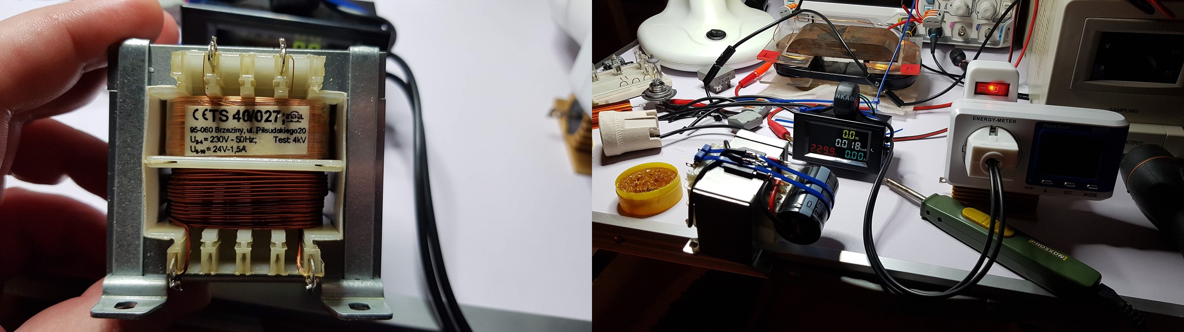
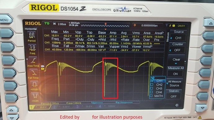
What I hope is by using the new measurement module I will get accurate real-time readings when powering up the ZPM as I actually measure the power before going into the transformer so the readings will not be affected by the signal sent back by ZPM.

By using this simple customized DC source I avoid having in readings the power consumed by the more complex DC source I used until now.

I'll see if this plan works.

The only concern I have is how to protect the transformer, its maximum current is 1.5A and while sweeping ZPM frequencies it's possible to find ranges where the current drawn by ZPM to go to 1.5A or higher. Also having that big electrolytic capacitor it's possible to have 1.5A or higher inrush current when powering up this custom DC source. I'm looking for a 1.5A current limiter so I avoid burning up the transformer, is there a simple solution for protecting it ?

"If you want to find the secrets of the universe, think in terms of energy, frequency and vibration."
Nikola Tesla
Vidura posted this 20 December 2019

Hey Fighter, Good to have you back on the bench. Really a good approach your new supply module. For the transformer you don't have to worry , it is not likely to damage it, unless it would be short-circuit for a considerable time. It will not output much more than the rated current. You can put a 2.5 or 3A fuse slow type, that's all needed to protect it. The current peaks will be drawn from the capacitor. Good luck with the experiments. Vidura.

Vidura

Close