Romanian ZPM (Zero Point Module) - Enhancements Stage

  • 4.1K Views
  • Last Post 28 November 2023
Fighter posted this 13 February 2023

This is the second imported thread (from the old aboveunity site) about my ZPM:


For references I will keep the original posting date for every imported post.

Note: This thread is public, everyone can see it, even the visitors which are not members here.

For the posts made by former aboveunity members which are not members on our site I'll use a member placeholder named UndisclosedMember.

Regards,

Fighter

"If you want to find the secrets of the universe, think in terms of energy, frequency and vibration."
Nikola Tesla
UndisclosedMember posted this 11 October 2019

lols yes, although it must be said. i dont see any nay-sayers.  more like kids in a candy store

Fighter posted this 14 October 2019

I've build the customized DC source for the PowerSource from Vidura, I tried to make it as compact as possible:

I put the bridge rectifier directly on the transformer's core so the core can be used as a radiator if the bridge rectifier becomes warm.

But there are two problems with it:

  • the 4700uF/100V electrolytic capacitor seems it's not doing its job very well, I have a 620mV Vpp, the capacitor is brand-new;
  • the output is not 12V as I expected, it's about 16V.

The transformer is 230V/12V and also brand-new:

@Vidura, I suppose this is not acceptable for powering up the PowerSource, isn't ?..

About voltage I suppose I could put a resistor on output for lowering those 16V to 12-15V but I'm not sure what electrolytic capacitor I should use in order to have a linear DC.

I need to check on the scope the output of the 12V secondary, maybe the factory put more turns on it and it's actually 16V there...

"If you want to find the secrets of the universe, think in terms of energy, frequency and vibration."
Nikola Tesla
Vidura posted this 14 October 2019

Hi Fighter, This voltage is normal when it is rectified and a capacitor connected. The rated transformer voltage is RMS , and so the output rectified and filtered will unloaded output the peak voltage. Anyway 16 volt should be ok, the driver IC is rated up to 18v if the resistors of the snubber circuit becomes hot you can lower the duty cycle on the preset of the module. Regards Vidura.

Vidura

  • Liked by
  • AlteredUnity
Vidura posted this 14 October 2019

I suppose that the scope trace is the ripple, 620mv is no problem at all , it is filtered again in the module , and the final stage, the power switch modules have a filtered voltage regulator, there will be pure DC always.

Vidura

Fighter posted this 14 October 2019

So this output is acceptable for PowerSource. Then next when I find some time I will start tests with ZPM.

Thanks for clarifications Vidura, I really appreciate your help...

"If you want to find the secrets of the universe, think in terms of energy, frequency and vibration."
Nikola Tesla
  • Liked by
  • AlteredUnity
UndisclosedMember posted this 14 October 2019

Hello Fighter. im liking your work. very much similar too mine, although your desk is in much nicer state ;=). 

i wonder how your machine will respond,  if you try too add a bridge rectifier across the output in addition too the light globe,  and put a second light globe at the bridge output,   ....

i am also curious if you were too use ONLY an output bridge , with a series globe on the bridge input, - and perhaps an additional globe on the output again,  i dont remember this being mentioned by our members as yet.

Fighter posted this 14 October 2019

Hi Patrick, thanks but you don't want to see the mess on my desk when I'm soldering something or repairing or building something new 🙂

About bridge rectifier on output, I had an attempt at the beginning, with a bridge-rectifier I've made with two channels and Schottky diodes (you can see images of it here: https://imgur.com/a/bn9gj).

It didn't worked, ZPM destroyed one of those electrolytic capacitors, the capacitor became that hot that I wasn't able to touch it for few minutes after I stopped the experiment. I suppose normal electrolytic capacitors are not made to withstand thousands of KHz frequency and considering these spikes of 100-200V I see on scope on output sometimes that poor capacitor had no chance because it was 10000uF at just 50V. Right now I don't intend to try that but I may try again in the future if I find electrolytic capacitors capable to work at ZPM's frequency. That was a failed attempt and I will need to find the cause of the failure before trying again.

"If you want to find the secrets of the universe, think in terms of energy, frequency and vibration."
Nikola Tesla
Fighter posted this 14 October 2019

Today I found about one free hour so I've experimented with ZPM and Vidura's PowerTool.

I recorded this video:


Sorry I'm not that good at presenting, while i was talking I tried to not miss anything relevant therefore the pauses/delays - while talking I was always thinking what to talk about next.

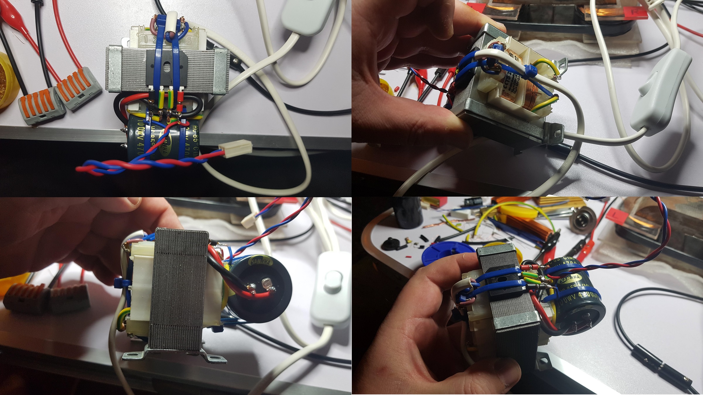
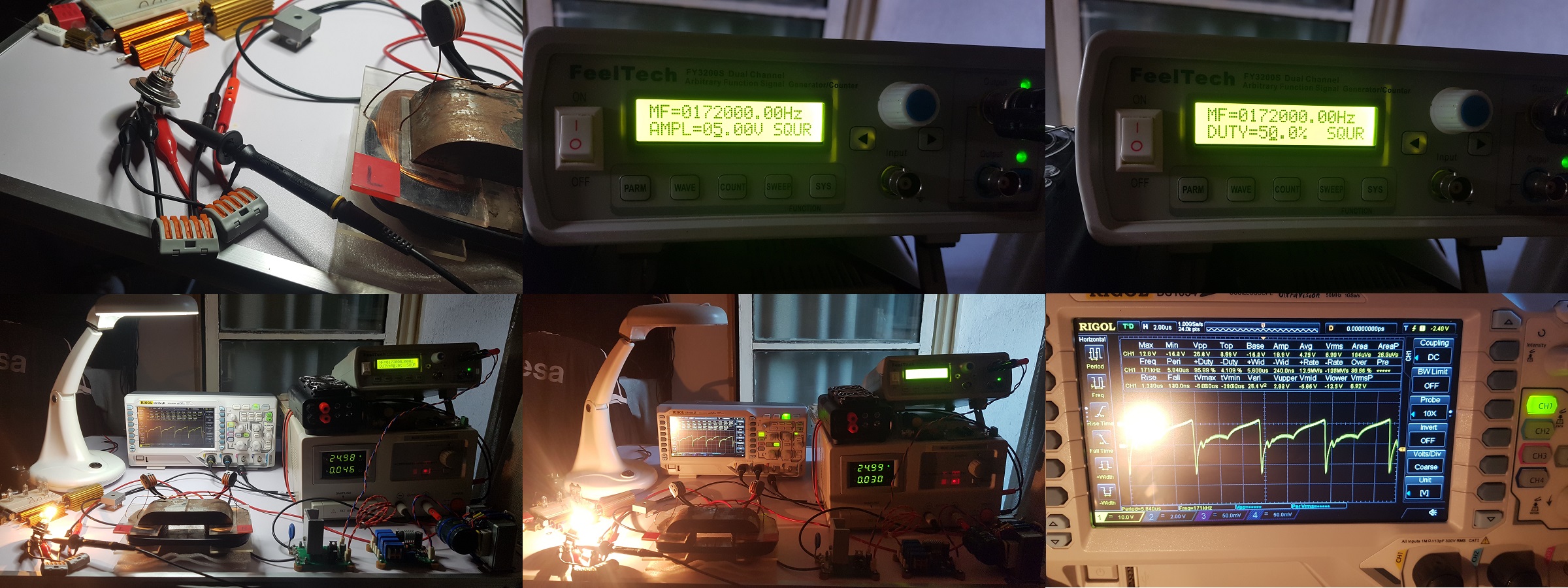
Here are some images taken with this configuration.

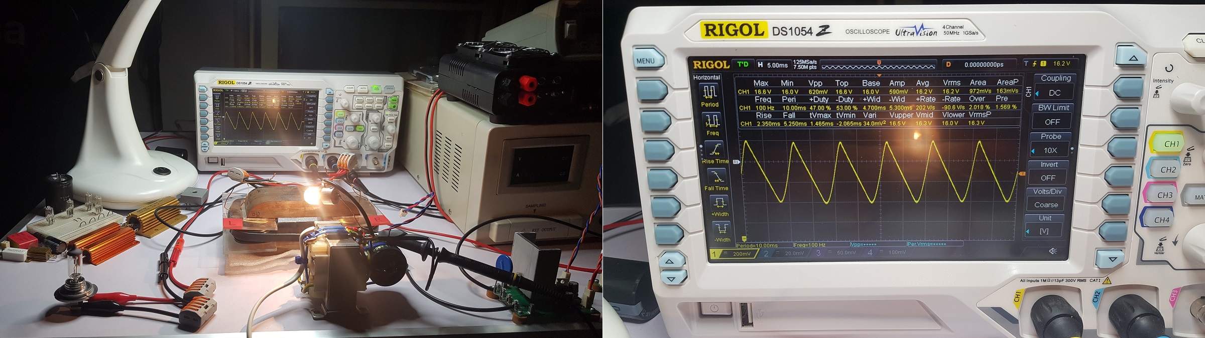
In these images I have the oscilloscope's probe connected directly on ZPM's output:

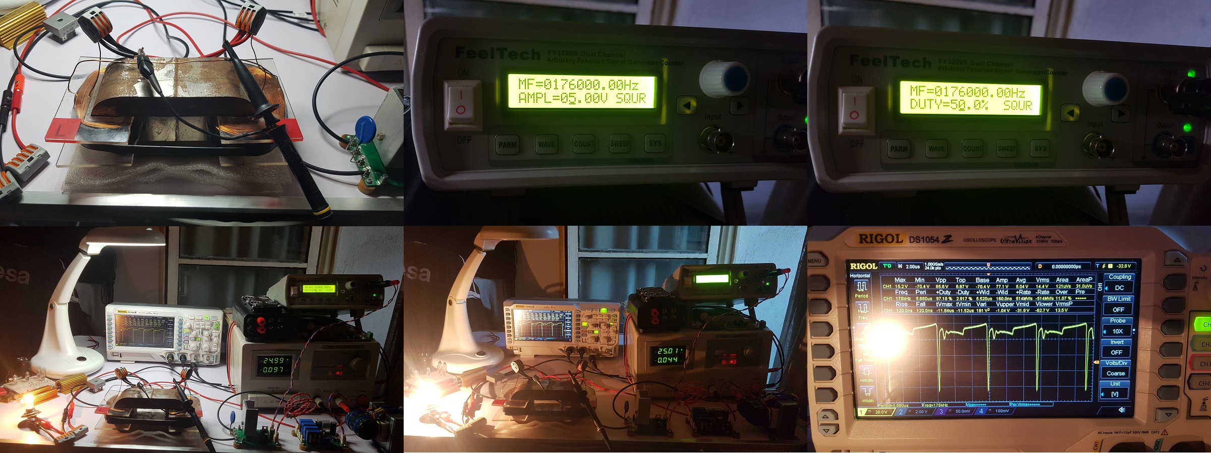
And in these images I have the oscilloscope's probe connected on the light-bulb's pins:

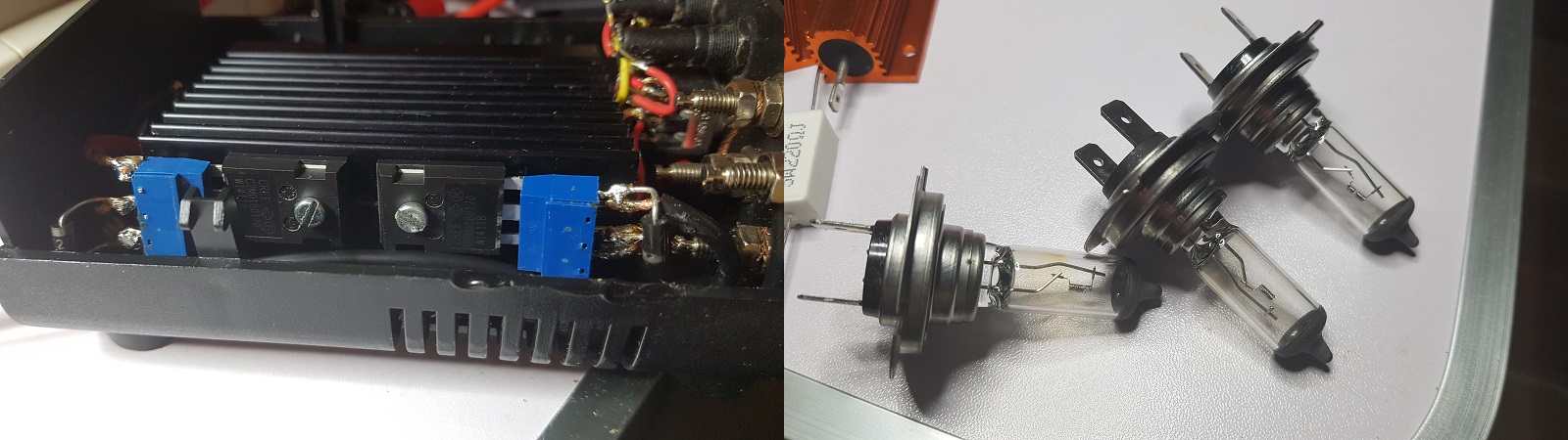
MOSFET driver but the cause could be that my driver is using one of those Cree MOSFETs, I intend to use one of those on the PowerSwitch in the near future.

A difference I noticed is the light emitted by the light-bulb on output seems to be pulsing at high frequency but it's noticeable, this is not something bad it's just something different.

As it happened with my MOSFET driver too, the MOSFET's radiator on the PowerSwitch is becoming very hot in 20-30 seconds so in order to be able to have longer experiments I'll need to build a active cooling system for the PowerSwitch like I did for my MOSFET driver.

"If you want to find the secrets of the universe, think in terms of energy, frequency and vibration."
Nikola Tesla
  • Liked by
  • AlteredUnity
Fighter posted this 14 October 2019

Another thing I did was to put high-voltage super-fast SF28G diodes on the MOSFETs but I had some problems with this, when exploring with different frequencies few times I had sudden surges of the power drained from the DC source, the source entered in auto-protection and the 12V/55W light-bulbs from ZPM's output became extremely bright and were destroyed. So far I lost 3 light-bulbs of that type, I have only one left which is still functioning:

For some reason seems ZPM doesn't like those protection diodes and at certain frequencies it suddenly starts draining full power from the DC source and smoking the 12V/55W light-bulbs.

For now I have set optimum frequency and the 12V/55W light-bulb seems to work fine but probably as soon as I will encounter one of those frequencies the same thing will happen again. If it happens probably I'll remove these protection diodes, I don't like this behavior and it's provoking damages, I don't know what's the reason but it's a fact.

And another (short) update: I definitely need to remove these diodes because while setting back my MOSFET driver and finding optimal frequency I encountered again one of those frequencies, this time the light-bulb survived, the DC source entered in auto-protection mode but one of the Cree MOSFETs from the driver (from the channel which was in use) is dead. Definitely ZPM don't like those diodes there and they are provoking too much damage, I will remove them as soon as I find some time to take care of this...

"If you want to find the secrets of the universe, think in terms of energy, frequency and vibration."
Nikola Tesla
  • Liked by
  • AlteredUnity
UndisclosedMember posted this 15 October 2019

Thiis strange flashing effect, is also present on my ZPM build. - however i think its due too the output on the signal generator. - which i do not believe is damaged.  it only happens as specific frequencies, - that i have noticed. - around 100-200khz. but critially it seems tied too the output voltage of the signal generator. -  

i am using IRFP N250's ,  which taper off between about 100khz and 800khz., and they seem too appreciate about 8-11v from my identical signal generator.  - and will not operate directly from the signal generator without at least 5volts. -    but i seem too recall when you were using the identical transistors, you had your signal generator voltage turned right up.  - which is also what i have been doing....  - this prevents the flashing phenomenon so far as i can tell .yet.

Close