Romanian ZPM (Zero Point Module) - Enhancements Stage

  • 4.1K Views
  • Last Post 28 November 2023
Fighter posted this 13 February 2023

This is the second imported thread (from the old aboveunity site) about my ZPM:


For references I will keep the original posting date for every imported post.

Note: This thread is public, everyone can see it, even the visitors which are not members here.

For the posts made by former aboveunity members which are not members on our site I'll use a member placeholder named UndisclosedMember.

Regards,

Fighter

"If you want to find the secrets of the universe, think in terms of energy, frequency and vibration."
Nikola Tesla
Fighter posted this 15 October 2019

Yes that is correct, I'm using minimum AMP (5V),I'll try to go up with the AMP value of my signal generator. I don't know how much I should go, I don't want to damage the PowerSwitch but this could be the cause.

Also recently I removed that red tape keeping together both pieces of the Metglas and I'm using a zip tie now, that could be a cause too, maybe that zip tie is not keeping the Metglas pieces together tight enough and there is a small gap in the center of the Metglas.

I'll investigate, thanks Patrick.

"If you want to find the secrets of the universe, think in terms of energy, frequency and vibration."
Nikola Tesla
Fighter posted this 15 October 2019

I also had some private messages exchange with Vidura so it seems for avoiding that light-bulb flickering I should go up with the AMP on my signal generator while monitoring the voltage on PowerSwitch's MOSFET gate. I will take care of that when I find some time, sorry about this but I still have things to learn and to accommodate myself with Vidura's PowerTool.

Edit: One of Vidura's PowerTool tutorials is about this calibration step for the signal generator, I saw this video but I didn't do this step:


I'll need to do this one-time calibration step for AMP on signal generator in order to have it working well with PowerTool and avoid that light-bulb flickering.

"If you want to find the secrets of the universe, think in terms of energy, frequency and vibration."
Nikola Tesla
Fighter posted this 17 October 2019

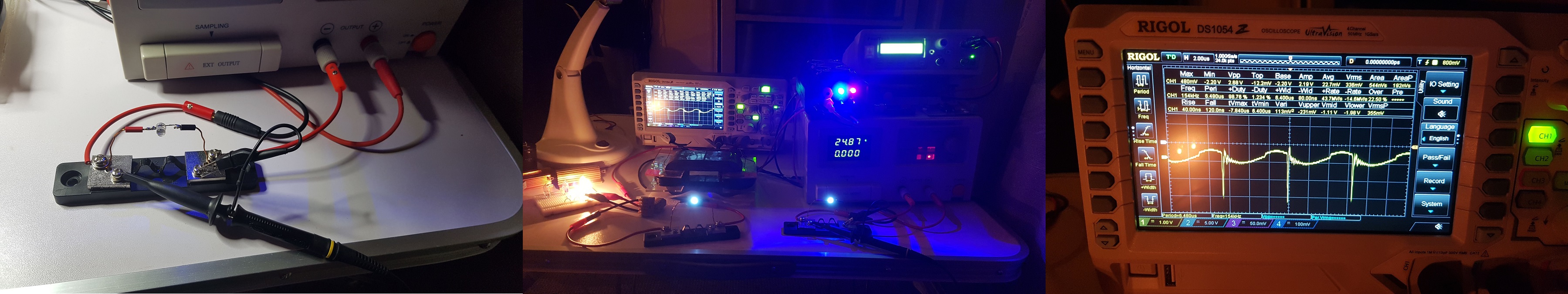
I replaced the dead Cree MOSFET from my MOSFET driver and removed the diodes which caused problems and provoked damages:

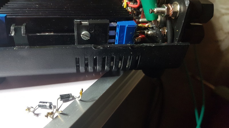
Unfortunately this new MOSFET had a short life, I had an experiment where I tried to use a choke-coil to smooth the voltage produced by a 10A/75mV (0.0075 Ohm) current-sensing shunt on the input.

I learned a lesson, choke-coils provoke damages if they are placed anywhere in the circuit. The choke-coil made the DC source enter in auto-protection, burned the new Cree MOSFET and also destroyed the last 12V/55W light-bulb I had:

I remember I had similar damages before when i tried to use choke-coil put on DC source's output trying to smooth the noise/spikes coming back from ZPM.

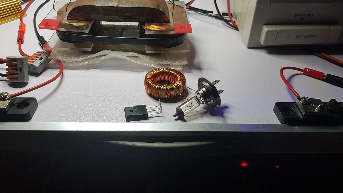
So right now I'll need to order some new 12V/55W light-bulbs and as the last Cree MOSFET is already placed in the MOSFET driver probably I should order some new Cree MOSFETs too.

Until then I still have some halogen light-bulbs, I'm gonna use 2 x 12V/35W on output.

The goal of the choke-coil experiment was a first step in the process of building a real-time current and voltage sensor on input and output without oscilloscope, using just some 10A/75mV current-sensing shunts.

As this one experiment failed I changed the approach: what about using (for the beginning) some LEDs as visual indicators of the current passing through the shunts ? Of course that's not a precise measurement but the LEDs could provide at least a clue of what's going on with the current on input and output in real-time while experimenting with different parameters on the signal generator. A next step would be, if I succeed in rectifying the voltage provided by those shunts, to place digital voltmeters measuring in real-time the voltage provided by the shunts so actually providing in real-time the accurate current measurements on input and output.

So for this first step (LEDs as visual indicators for current) I took two identical LEDs from two identical Chinese lighters where those LEDs are powered by 3 x SR626SW (1.55V) batteries:

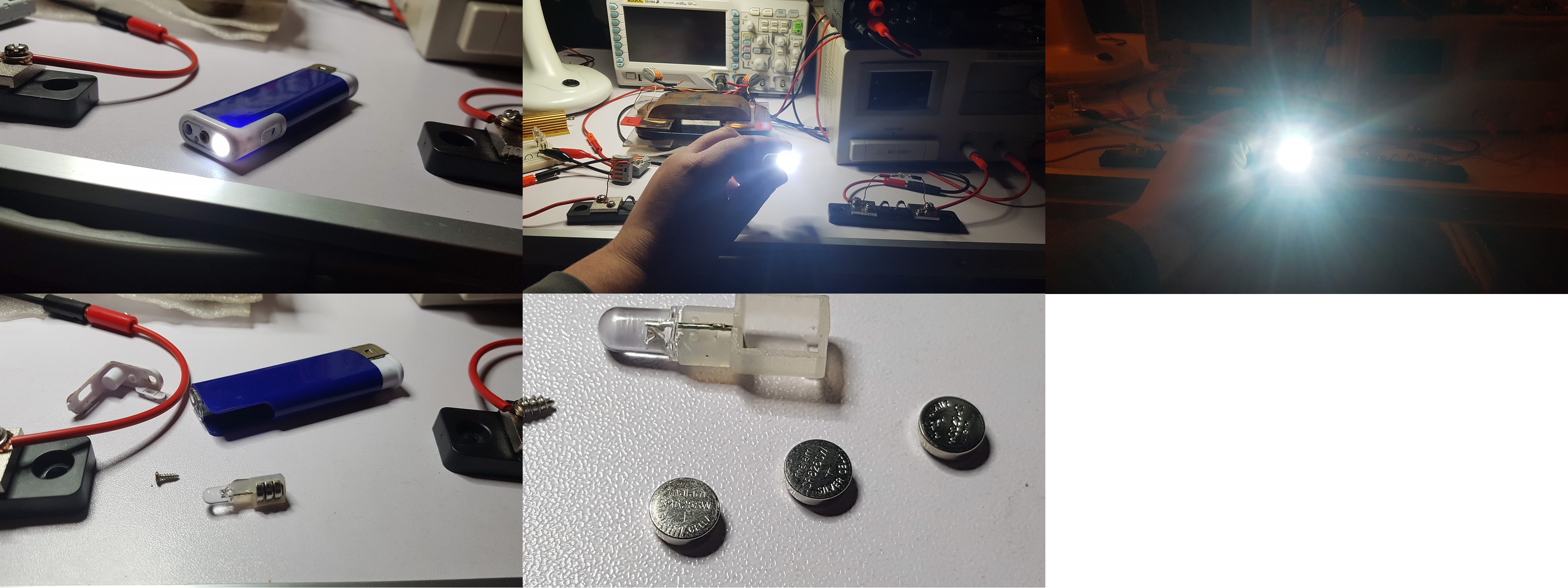
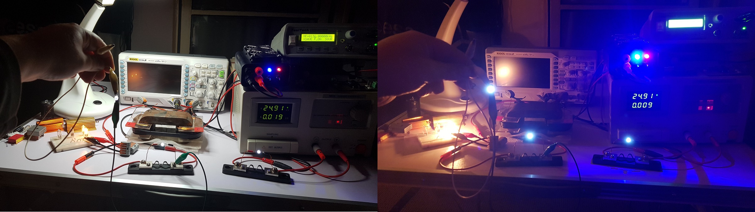
So this is the result:

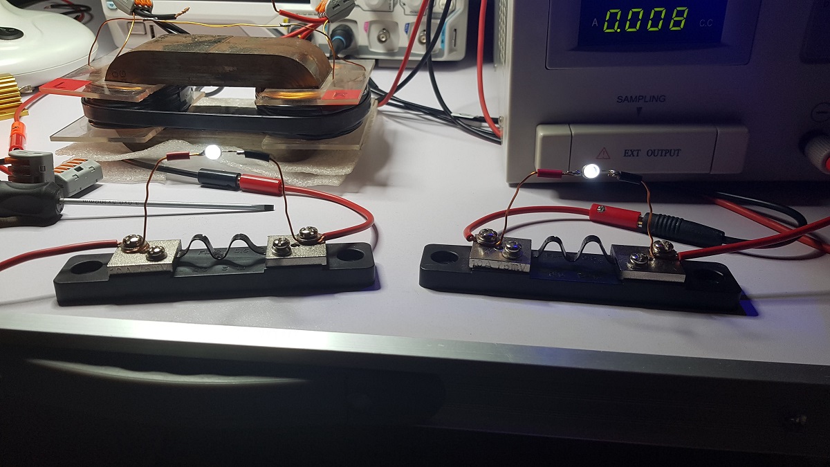
So for now I have some real-time visual indications on current values on input and output.

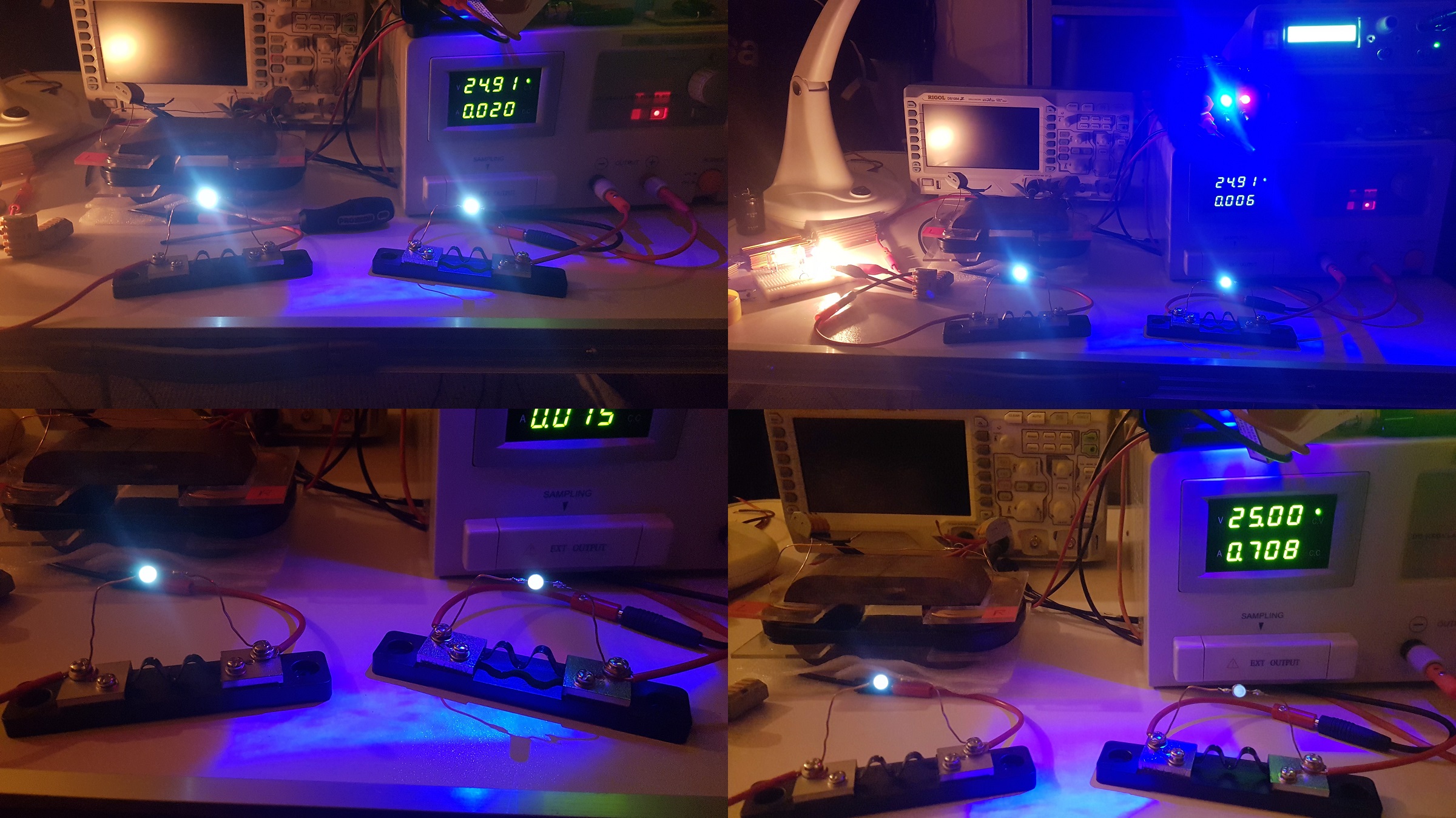
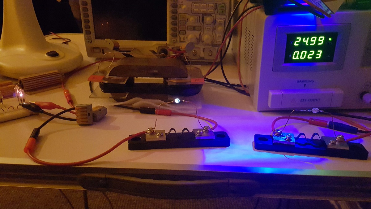
From now on I can experiment not only with frequency but also with AMP and duty-cycle on my signal generator and see what's going on with the current on input and output. In the following photos I tried changing these parameters. In reality the luminosity difference between the two LEDs is easy to observe but seems my phone is amplifying low luminosity sources and dime high luminosity sources when taking photos in dark. But still you can see these differences:

Just as a note: the current-sensing shunts are identical and the LEDs are identical in luminosity, I verified that by switching the shunts and LEDs between input and output and having the same results (in terms of LEDs luminosity). So I checked that both shunts and LEDs have the same characteristics.

And I took one photo which I think is very significant, I played with parameters in order to see if I can have the LED on input off while still having the LED on output on. In this photo you can see the current on input is clearly not enough to light that LED while on output you see the LED still on and also on the left 2 x 12V/35W halogen light-bulbs still on:

I am aware about the voltage differences between input and output but considering on input we have 25V and on output we have spikes between 100V and 200V in my opinion this image gives an additional clue about ZPM's over-unity.

The next goal in building this real-time measurement system is finding a way to smooth the voltage provided by the shunts so that voltage becomes DC:

If I can have clean DC voltage provided by the shunts then I can use it it with some digital voltmeters I just bought so I can have accurate real-time digital display of currents on input and output.

So for now the problem is how I find a way to get DC from this but without choking-coils:

I'm thinking of building bridge-rectifiers using these SF28G super-fast diodes then maybe some capacitor(s) for smoothing the voltage. I'll see how it works.

I'll post updates as I find time to continue the experiments...

"If you want to find the secrets of the universe, think in terms of energy, frequency and vibration."
Nikola Tesla
Vidura posted this 17 October 2019

Hey Fighter,
Sorry about the losses of the Mosfets, they are kind expensive. If I may make a couple suggestions to avoid this damages on your custom made switch:
use MOV as surge protectors on the drain - source terminals, the max. value K420 which clamps around 1100V maybe better a K400 for more safety margin. Do not attach other components as the Mosfet on the heat dissipator, although you use insulation pads, the high frequency currents will pass thru. Be careful when placing a grounded scope probe on the center tap of the coils, as this will shift the hot end (longitudinal high potencial) to the other terminals, where the switch and Power supply are placed , and may cause interferences and failure.

I wanted to say that I love the idea with the LEDs on the current shunts, this visual indicators really make our work easier, maybe you could add a second led with oposite polarity to the shunt, which will give indication on the direction of the currents also. keep up your good work, VIDURA.

Vidura

  • Liked by
  • AlteredUnity
Fighter posted this 17 October 2019

Hi Vidura,

Yes they are really expensive and unfortunately they die so fast on every failed experiment. What can I say, I expected them to be more resilient but this is the cost of researching this kind of devices we're working with...

Right now I don't know what exactly changed in device's behavior when I placed those SF28G diodes between drain and source but after that I saw appearing these dangerous frequencies which killed MOSFETs and light-bulbs, that's why I removed the diodes. They were supposed to do exactly this - protect the MOSFETs, but it was exactly the opposite.

Right now I kind of hesitate to try with MOVs between source and drain of the MOSFET as this is the last Cree MOSFET I have until I can order another batch, I'll try when I'll have some backup MOSFETs.

About attaching other components on the radiator inside the MOSFET driver, I will not, I had that voltage regulator attached before but I found a solution to power that LED on the front panel without the voltage regulator. So right now I have only one MOSFET attached to the radiator, for the other channel of the MOSFET driver the MOSFET is missing, didn't mounted one there anymore.

About the center tap of the coil, I've made measurements there with oscilloscope probes some time ago, didn't had any problems or failures, are you saying that could destroy my equipment ?..

Thanks, necessity force us to build the tools we need for this kind of devices... šŸ™‚ These LED indicators are just the beginning, I will try to get pure DC voltage from those pulses you see on the scope in my previous post, if I succeed then I'll be able to use that DC voltage with digital (and maybe analog) voltmeters which will actually show accurate real-time current measurements on input and output, I hope I'll find a way to accomplish that.

Yes, having a second LED with opposite polarity is also a nice idea and very useful, that way we can "see" the currents going in both directions through the shunts, I will try that, let's see how it works šŸ™‚

"If you want to find the secrets of the universe, think in terms of energy, frequency and vibration."
Nikola Tesla
  • Liked by
  • AlteredUnity
Fighter posted this 17 October 2019

idura, I tried putting a LED with inverse polarity on both shunts (from input and output), the LED doesn't light up at all.

But I found something on output, when connecting LED's positive (green connector) to the negative of the other LED while the negative of the LED (white connector) is in air we have some kind of one-wire transmission, the LED light up just as powerful as the one from the shunt šŸ™‚

This makes me think of something, should I be concerned about the electromagnetic radiation around this thing ?...

Maybe I should make a box covered with aluminum foil like a full Faraday cage to cover ZPM while it's active ? I was thinking about this sometimes before but I didn't noticed any negative effects while or after making experiments. Maybe I should reconsider this.

"If you want to find the secrets of the universe, think in terms of energy, frequency and vibration."
Nikola Tesla
  • Liked by
  • AlteredUnity
UndisclosedMember posted this 17 October 2019

When searching for a mosfet - I recommend this approach - Sort by rdson - look for as low as possible - find mosfet with appropriate voltage rating and lowest gate charge (Qg), pref around 50 nC or less. Check the price per unit and if it is reasonable then it may be worth using. You may need to compromise a bit, for this reason you may find that adapting your circuit to a lower voltage mosfet may offer an advantage.

A quick explanation of my perspective:

Thermal failure is a universal failure so low rdson is typically the most important characteristic, especially if the power is greater than a couple watts.

Voltage rating at first glance may seem important, but I've found that some circuits can easily exceed the voltage rating for a mosfet and the mosfet may clamp voltage at its avalanche voltage. So a mosfet rated at 60V may not fail immediately but could just avalanche (causing losses and extra heating). You can try to design a snubber circuit to clamp the voltage spikes to avoid needing to use a high voltage mosfet. So while operating voltage is an important consideration, there might be better ways to handle spikes than just using a HV mosfet. You can experiment with adding snubbing circuits and see if it negatively impacts AU device performance. I can't tell you if this is appropriate for your device.

Frequency range will determine if the gate charge along with the on/off and rise/fall characteristics are deal killers. For low frequencies, these details may be relatively unimportant, but once you start to go above a couple kHz these things may begin to make huge differences. Keep in mind, high rdson compounds any problems you will have here as the mosfet may spend less time fully on or fully off and rdson only tells you the lowest nominal resistance in the fully on state.

Anyway, these are just opinions from a non-expert. I am curious to know if you find mosfets that work well for your application. When you do, please share the part number.

  • Liked by
  • AlteredUnity
Fighter posted this 17 October 2019

Hi Zanzal, I'm also a non-expert but I find it's a lot to learn from your post.

C2M0160120D made by Cree/WolfSpeed seems to be the fastest HV MOSFETs on the market for now and, even if they are expensive, during my research (after Vidura told me about them) I didn't found information/opinions about more performant ones.

But using your criteria of selecting who knows, maybe I'll find others better in terms of matching ZPM's circuit, I'll keep these criteria in mind and I'll search.

Of course, if I'm gonna change the MOSFETs model I'll post updates here.

Thanks.

"If you want to find the secrets of the universe, think in terms of energy, frequency and vibration."
Nikola Tesla
  • Liked by
  • AlteredUnity
Vidura posted this 17 October 2019

Hey Fighter, I am using the Cree MOSFET s in all my latest experiences, and have not lost one till the moment, the performance is really excellent and the RDS on the lowest in that voltage range. But I always use MOV , it's a must, also the zener diodes for gate protection are strongly recommended, and I didn't note any negative side effects for using this protections. Regarding the effect of single wire transfer it is obvious, you have high frequency longitudinal oscillations, this is why the current not always behave like expected, and the reversal LEDs on the shunts might be off most of the time, but they will indicate when a reversal current flows, which might occur only with very specific parameters. I hope this helps and explain some things. Vidura

Vidura

  • Liked by
  • AlteredUnity
Jagau posted this 18 October 2019

es Vidura 

 zener diodes for gate protection are strongly recommended and a totem pole activation for the gate is also a must to preserve the shape waveform that activates the gate.

Hi fighter
I just received my metglass and I notice they have a very high saturation chest 1.56 Tesla compared a ferrite it is well better.
Nice experiment to do.

It is a hitachi amcc320

Jagau

  • Liked by
  • AlteredUnity
Close