Romanian ZPM (Zero Point Module)

  • Topic Is Locked
  • 3.5K Views
  • Last Post 12 February 2023
  • Topic Is Solved
Fighter posted this 07 February 2023

This is the imported thread (from the old aboveunity site) about my ZPM:

For references I will keep the original posting date for every imported post.

Note: This thread is public, everyone can see it, even the visitors which are not members here.

For the posts made by former aboveunity members which are not members on our site I'll use a member placeholder named UndisclosedMember.

Regards,

Fighter

"If you want to find the secrets of the universe, think in terms of energy, frequency and vibration."
Nikola Tesla
  • Liked by
  • Jagau
  • Inception
UndisclosedMember posted this 23 August 2019

 Some more info (let me know if this is a distraction and I'll clear it off)

Links to some Power Supply Output Impedance information:

The video at the end of this link's page is pretty good.
https://www.powerelectronicsnews.com/technology/output-impedance-as-an-important-design-parameter-for-power-supplies

Also;

DC power supply output impedance characteristics
https://community.keysight.com/community/keysight-blogs/general-electronics-measurement/blog/2016/11/08/dc-power-supply-output-impedance-characteristics

How can I measure output impedance of a DC power supply?
https://community.keysight.com/community/keysight-blogs/general-electronics-measurement/blog/2016/10/12/how-can-i-measure-output-impedance-of-a-dc-power-supply

It can get quite involved very quickly, but in general, to quote the Keysight (former HP) fellow [Steven Lee]:

"The impedance of a typical DC power supply’s output stage (like the conceptual one illustrated in the above referenced posting) is usually on the order of an ohm to a couple of ohms. This is the open-loop output impedance; i.e. the output impedance before any feedback is applied around the output. If no feedback were applied we would not have anywhere near the load regulation we actually get. However, when the control amplifier provides negative feedback to correct for changes in output when a load is applied, the performance is transformed by the ratio of 1 + T, where T is loop gain of the feedback system. As an example, the output impedance of the DC power supply operating in constant voltage becomes:

Zout (closed loop) = Zout (open loop) / (1+T)

The loop gain T is approximately the gain of the operational amplifier times the attenuation of the voltage divider network. In practical feedback control systems the gain of the amplifier is quite large at and near DC, possibly as high as 90 dB of gain.

This reduces the power supply’s DC and low frequency output to just milliohms or less, providing near ideal load regulation performance.

Another factor in practical feedback control systems is the loop gain is rolled off in a controlled manner with increasing frequency in order to maintain stability. Thus at higher frequency the output impedance of a DC power supply operating as a voltage source increases towards its open loop impedance value as the loop gain decreases. ..."

Again;

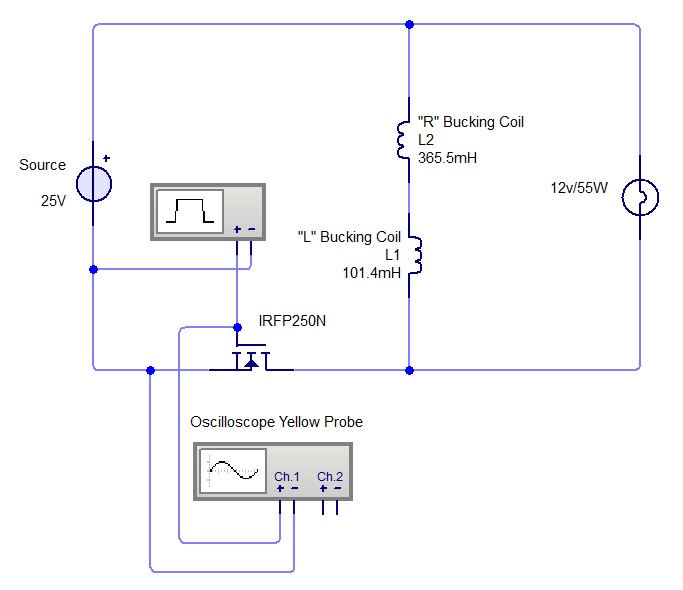
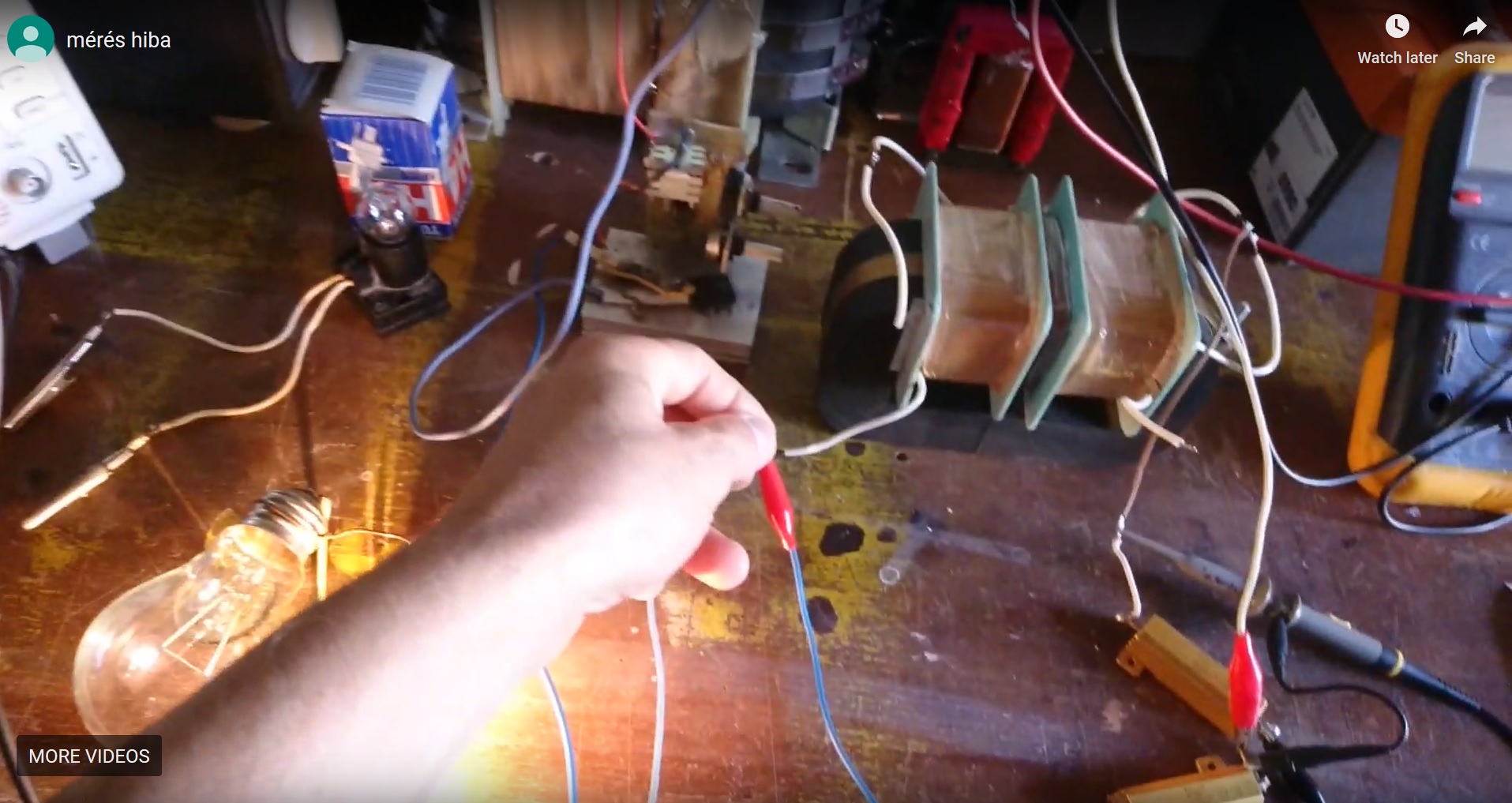
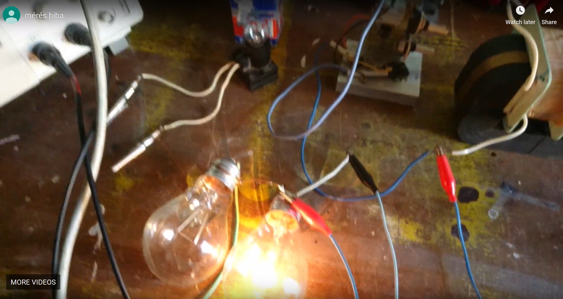
IMHO - your supply likely has less to do with things than the Coil/Transformer characteristics (self, mutual inductance, inter-winding and other capacitance, core B-H Curve, bulb impedance (it's a coil), cold bulb thermal resistance/impedance change as it heats up, MOSFET operating performance (many characteristics to consider), waveform (harmonics - FFT), etc...

All in all - your experiments present some really good, thought provoking, things, in my opinion. Thanks!

SL

  • Liked by
  • Inception
Fighter posted this 23 August 2019

@solarlab no worries, I don't consider it a distraction at all, your posts are welcome in this thread, feel free to post anytime you want.

I'm gonna read a few times your post ( like a beginner in electronics as I am šŸ™‚ ) in order to understand and I'll check the links and videos.

So you also think there are intriguing things about this device, isn't ? šŸ™‚

Thanks !

"If you want to find the secrets of the universe, think in terms of energy, frequency and vibration."
Nikola Tesla
UndisclosedMember posted this 24 August 2019

Thanks guys !

You have "Generated" a full: ā€­3.574784ā€¬ Watts above your Input for a COP: ā€­1.09396ā€¬

(before going to vacation) the ZPM didn't worked at all, the DC source entered in auto-protection mode, the voltage stabilizer which powers that LED in the MOSFET driver was burning and smoking and I had the impression the MOSFETS themselves didn't felt very well, they were heating up quickly so I did shutdown the experiment. The voltage stabilizer (powering that LED) is destroyed again šŸ™‚

Hi Fighter !!.  I am with you on the aggressive defense of our planet. -  but its no good without democracy. - at least i keep telling myself that   .... so i refuse too drink the cool aid, - we must be smart, and good, and god is on our side. technology can save man.

Also i am so sorry too hear about your equipment issues, - but i think i know why, - its same problem i am having with my newman motor. - i suspect that your transistor junctions are not closing properly. -  and il cut right too it, - i purchased the identical signal generator too you from ali express. - because it is the cheapest sweep generator i could find. .. HOwever. the bloody thing has one unexpected design flaw. - the duty cycle -    i think this may be the problem,  - when it is run @ 25% etc etc. - the negative offsets, dont drop too 25% also, like my other signal generator, - the offsets go up too 75%. thus are pulling your base's down, and allowing current too backflow through the emitter. - and this can cause damage and overheating.///   i figured you know about this already, since im were working on the same stuff here. - but incase you didnt pickup on that. i also suggest building a resistor box with 40 values or so, and finding the best gate > emitter pull down resistor for a given voltage.

also, i have only made about 20 coils so far, - but i have noticed generally speaking, the frequency drops, with more resistance. - but there have been about 20% exceptions too this rule,  which is a huge margin of wtf.  - any ideas on that ?


Hi SOLARLAB; you are very much barking up a tree their my dear friend. - i would love too know the absolute values of my bench equipment, - but the truth is, its all dynamic. - my advise is too put a capacitor on the output and ignore it, or 2 if you have too..  -  although if you have any suggestions , they sound alot of fun !

  • Liked by
  • Inception
Fighter posted this 24 August 2019

@patrick1 sorry, I don't follow, my signal generator is doing what ? I'm not aware of any design flaw.

This is from an old post, if there would be that flaw I think it would show on the oscilloscope, it would alter the signal badly:

So I connected the yellow probe to the MOSFET: probe's ground to the source and the probe itself to the gate:

This measurement's schema is the following:

The MOSFET driver's switch is off so ZPM is not powered but the signal generator is on and is already sending signal to the MOSFET which is shown by the oscilloscope:

Then after turning MOSFET driver's switch on the ZPM is powered on and the readings from the MOSFET are in the next image:

Could you show me how you found that flaw and how can I check if my signal generator has that flaw ? In my case that voltage regulator (which is regulating voltage from 0V-30V to 12V for that LED you saw on my MOSFET driver) was blown up only when I put a choke-coil on the positive wire of my DC source's output. I suppose that the voltage coming to that voltage regulator was above its 30V limit and it couldn't handle it properly and started to emit smoke. But that's no issue, the MOSFET driver is functioning properly just right now I don't have a visual indication when its switch is on or off because that LED is not functioning anymore.

About optimal frequency in my case I found no exception from the rule, as the load increases (and so resistance on output) I always need to lower the frequency in order to find another one. For example if I have on output a 12V/55W light-bulb and I add another one 12V/55 light-bulb the new optimal frequency go down with 100 maybe 200KHz. As I continue to add more light-bulbs on output the optimal frequency go down until it goes below 100KHz where ZPM starts to draw more and more power from the DC source and it's behavior changes and becomes very inefficient. This is what I observed from my experiments. I found no exception where adding another light-bulb on the output the new optimal frequency to be higher than the old optimal frequency.

"If you want to find the secrets of the universe, think in terms of energy, frequency and vibration."
Nikola Tesla
  • Liked by
  • Inception
UndisclosedMember posted this 24 August 2019

Hi Fighter. - thankyou, im glad that we have observed the same results. in relation too frequency and loading... i think the anomaly i registered was due too a particular experiment with 32 gauge wire. - it is so thin that a 10ohm coil, equates too about 60-70turns, and weights about 1gram, - what i am talking about is very nieche`, and critically very low power., allowing other insignificant factors too play a larger roll, -

but more importantly, regarding your signal generator, - when you are in 25%duty cycle., the transistor is on, - and when you go "off".  for 75%, it is not really off ( this is my estimation , unless you have solved it with a diode on base ).  because when you pull a NPN transistor's base too negative, - it can and will cause a reverse flow situation too occur, at a much lower voltage, than it normally would. - and in the interests of future development, you are not going too be able too replicate this factor in future designs, - so its best too elliminate it now, - and control the current flow, i would suggest adding a diode in series with the base.,- and if permissable, also a 10k~ pull down resistor from the base too emmiter..... and if you dont already, ))) . a diode from your IRFP250N, too negative rail.

i suggest do all of these, as they may improve your experiement, - but also, because it will allow you too control the current flow, and remove the possibility of "unexpected and unknown" behaviour...   creating a more solid learning foundation    . please forgive my bluntness.  but i recommend because i believe this will help and happy.

  • Liked by
  • Inception
  • AlteredUnity
UndisclosedMember posted this 24 August 2019

Hey Fellows,

Not uncommon for me to be a bit lost so let me ask:

With this circuit (opposing wound series coils, pulsed on and off at a certain duty cycle, and a light bulb in parallel with the series coils) what is the primary objective; or what, briefly, do you anticipate will be the result?

And, why do you think this result might come about?  What might actually cause this result?

Just curious as always, thanks in advance!

SL

  • Liked by
  • Inception
Atti posted this 25 August 2019

Hi SL and everyone.


or what, briefly, do you anticipate will be the result?

And, why do you think this result might come about? What might actually cause this result?

That's a good question! I agree with the approach.
Expand: How can we use it with other larger machines?
Of course, only if the higher performance is fully proven and there is no measurement error.

  • Liked by
  • Inception
Fighter posted this 25 August 2019

@Atti

Of course, only if the higher performance is fully proven and there is no measurement error.

I'm sorry ? That sounds like a demand. Without time invested and research no device gonna be "fully proven" by itself. Excuse me for being so blunt this time but what about joining the research and doing experiments with ZPM, not just passively waiting for someone to do all the research and even demanding things ? You have all the information you need here. What about this approach ?...

About the measurement error, I think we passed that stage, there are oscilloscope results with screenshots and all the details. Thank you.

"If you want to find the secrets of the universe, think in terms of energy, frequency and vibration."
Nikola Tesla
  • Liked by
  • Inception
Fighter posted this 25 August 2019

@patrick1 I think I understand what you mean. So you're saying that flaw is actually used by ZPM to send power back to the DC source ? It's a possibility because for sure I detected power coming back to the DC source but didn't understood what's the mechanism used by ZPM to send power through MOSFET driver.

If that flaw is real that means at some point I need to "blind" the ZPM and make it stop "seeing" the DC source as load and use that power to do real work like powering up additional load on output.

But the project is not at that stage yet and can't do this right now, let me explain why: from my experiments seems that large capacitor from inside the DC source is actually playing a certain role and is being a part of ZPM actually. ZPM is actually using it as its own component and may be one of the reasons why the experiment when I tried to replace the DC source with batteries failed.

I agree that at some point I'll need to replace the DC source with batteries but for the reason I explained before I'm not at that stage yet. But I'll keep in mind the possibility of that flaw.

Thanks.

"If you want to find the secrets of the universe, think in terms of energy, frequency and vibration."
Nikola Tesla
  • Liked by
  • Inception
Fighter posted this 25 August 2019

@Atti My measurements are made through oscilloscope now and I posted them so where the measurement errors would be ? So your opinion about "measurement errors" is based on what exactly ?

I also have years of investments in time, work and money BUT I'm sharing my data here making it possible to others to replicate my results, do their own research and share what they find here.  So far didn't saw anyone joining and more than that, even if I provide details with oscilloscope screenshots and all the stuff, I still see doubts. I agree digital voltmeters and ampere-meters could have measurement errors (like you show in your video) with this kind of devices but how an oscilloscope have measurement errors ?

If you still have doubts there is a way: replicate ZPM, make your own research and measurements (using oscilloscope) and (if you find them) show me where the measurement errors would be. I would be curious to see how it works on your side, I provided all the required details for replication here, nothing is missing. Come here and say "hey, I replicated ZPM, made measurements but the results are not like your results. here is my research and data". Then you would have real arguments and data to justify your doubts. Without that anyone can have "doubts" about anything and talk in general about "measurement errors" regarding any kind of device.

I will stop my replies here with a single conclusion: Prove to me that I'm wrong. Show me your test results. Thank you.

Edit: I see in your video you're already working with a ZPM replication (just the coils are on top of the Metglas core, not on lateral sides) and even powering a 220V light-bulb. And you still have "doubts" and talk about "measurement errors" ? I don't see any measurement data on your oscilloscope, did you measured with oscilloscope and still found measurement errors ? Why not sharing your ZPM replication project and your progress ?

Interesting, talking about sharing...

"If you want to find the secrets of the universe, think in terms of energy, frequency and vibration."
Nikola Tesla
  • Liked by
  • Inception
Close