Romanian ZPM (Zero Point Module)

  • Topic Is Locked
  • 3.5K Views
  • Last Post 12 February 2023
  • Topic Is Solved
Fighter posted this 07 February 2023

This is the imported thread (from the old aboveunity site) about my ZPM:

For references I will keep the original posting date for every imported post.

Note: This thread is public, everyone can see it, even the visitors which are not members here.

For the posts made by former aboveunity members which are not members on our site I'll use a member placeholder named UndisclosedMember.

Regards,

Fighter

"If you want to find the secrets of the universe, think in terms of energy, frequency and vibration."
Nikola Tesla
  • Liked by
  • Jagau
  • Inception
cd_sharp posted this 06 September 2019

Hey, Atti, nice work.

Careful, Metglas is electrically conductive and the edges are very sharp, they would easily destroy any enamel isolation on the copper wire. I quit using Metglas without good spools, I've had some arcs between the coil and the core and the core heated.

Hope this helps.

If you know how to build such a device and you're not sharing, you're a schmuck! - Graham Gunderson

  • Liked by
  • Inception
Atti posted this 07 September 2019

Hello everyone.
@Fighter


- The core size is different. It is smaller. If it were exactly the same, then an accurate comparison could be made. Optimal inductance should also be found.
- I have tried both magnetic directions but the directions shown are opposite. You can see this from the measured inductance.

I've tried every frequency at every frequency. But the pwm generator needs to be converted.
-COP measurement. At the end of the video, you can see the number of spikes on the resistance wire (0.1 ohm) used to measure current. With and without load. This makes accurate measurement impossible. For the time being.

@Vidurra
-I don't usually withhold information. Since I was given the opportunity to do the experiment, I think it's fair to show all the data to someone else. It doesn't matter what the results are. You can learn a lot from a bad result.
The fet (IRF 540) is powered by a 555 timer.
-I have currently considered this the best for measuring current, but it is not shorter. That's why it is folded for inductance.

@cd_sharp
Thanks for the idea.

@ Patrick1
In my opinion, the diode or the zener diode alone is of little use. Exercise can come in handy.

I'll keep going

  • Liked by
  • Inception
Fighter posted this 07 September 2019

- The core size is different. It is smaller. If it were exactly the same, then an accurate comparison could be made. Optimal inductance should also be found.
- I have tried both magnetic directions but the directions shown are opposite. You can see this from the measured inductance.

Yes, the core size is different, I know. I meant the magnetic properties and the hysteresis of your core should be the same. Including the same ratio between iron, nickel, molybden, boron and cobalt in the alloy composition of the core. The production process of Hitachi is well controlled and very precise. You use the same turns ratio (150/300) as in my ZPM so your core should behave the same way as mine, the difference of size doesn't really matter. About magnetic fields, yes, from your inductance measurements it seems the fields are opposing indeed. When I built my ZPM I double-checked by powering each coil and checking its upper side is producing North magnetic polarity and it's lower side is producing South magnetic polarity like this:

I've tried every frequency at every frequency. But the pwm generator needs to be converted.

I agree, finding manually the optimum frequency in a range of 0KHz - 1MHz is impractical. The process should be driven by a signal generator having frequency sweep feature.

- COP measurement. At the end of the video, you can see the number of spikes on the resistance wire (0.1 ohm) used to measure current. With and without load. This makes accurate measurement impossible. For the time being.

I'll keep going

About COP calculation you could use Vrms and Vavg shown on your oscilloscope as we did in previous posts for my ZPM. I agree - experimenting with ZPM and adapting equipment to its behaviour requires some time...

"If you want to find the secrets of the universe, think in terms of energy, frequency and vibration."
Nikola Tesla
  • Liked by
  • Inception
Fighter posted this 07 September 2019

Hi guys,

UndisclosedMember asked me to consider adding a Paypal donation button at the top of this thread.

So you can find it at the beginning of the ZPM thread here:

https://www.beyondunity.org/thread/romanian-zpm-zero-point-module/

or in this post here:

If you find ZPM intriguing and the experiments and data I share here with you useful for your own projects and research, you may help the further research by donating:


Your support will be very much appreciated and it will be used ONLY for equipment and building customized electronics for further research and experiments.

If you're working with a ZPM replication please share your findings here like I do so we can enhance this device.

Thank you,
Fighter

"If you want to find the secrets of the universe, think in terms of energy, frequency and vibration."
Nikola Tesla
  • Liked by
  • Inception
Atti posted this 07 September 2019

Hey Vidurra. There's the drawing.

  • Liked by
  • Inception
cd_sharp posted this 08 September 2019

Hey everyone,

I've just experienced some problems at 20Khz with these current sensing resistors:

In this picture I should see a 0.000A linear on the light blue trace

which is the voltage over a resistor while no current flows through it. The problem grows with the frequency. So, any ringing in previous measurements should be ignored, they are not there for real. I could verify these shunts do a very good job below 1KHz.

I'm planning to move on to another model.

If you know how to build such a device and you're not sharing, you're a schmuck! - Graham Gunderson

  • Liked by
  • Inception
UndisclosedMember posted this 08 September 2019

Hey CD,

What is the circuit to test the Current Resistors?

With any high frequency circuit, the general rules are keep the leads short as possible, try to make a general effort to minimise Inductance throughout.

Lets have a good look and see what we can find on these Resistors, we did look before and they did come up ok: Here

  • Liked by
  • Inception
Fighter posted this 08 September 2019

@Cd_Sharp: I don't think there is something wrong with the resistors. The ringing is present on DC source's output even without the resistors present in the circuit, they just send to the scope's probe what they "see" in the circuit. In many of the previous posts I presented what the scope shows when one of its probes is put in parallel on DC source's output. Your device has a Metglas core identical with mine and it's using bucking coils just like ZPM. In my opinion (based on previous scope images I posted here of DC source's output without resistors present in the circuit) the ringings are real, they mean that your device is sending power back to the DC source just like it happens with ZPM.

In the shipment I received recently from China I have 3 x 10A/75mV current-sensing shunts, two of them will be the base of a real-time COP measurement system, they will be placed on input and output. And one of them I don't intend to use it in this system, I ordered one additionally just in case I need to make other measurement except input and output. They're part of the same lot and should be identical in their characteristics so I'll have a common criteria of measurement on input and output. If you want I can give to you the spare shunt as long as you need it so you can give it a try and experiment with it. Just let me know and we can meet. With this occasion I will return the shunt I borrowed from you, I kind of kept it for a long time, sorry about this...

Below is a photo of one of the shunts and also a photo with two of the shunts on input and output:

"If you want to find the secrets of the universe, think in terms of energy, frequency and vibration."
Nikola Tesla
  • Liked by
  • Inception
Fighter posted this 09 September 2019

And as an update, seems today was not a good day for science... šŸ™‚

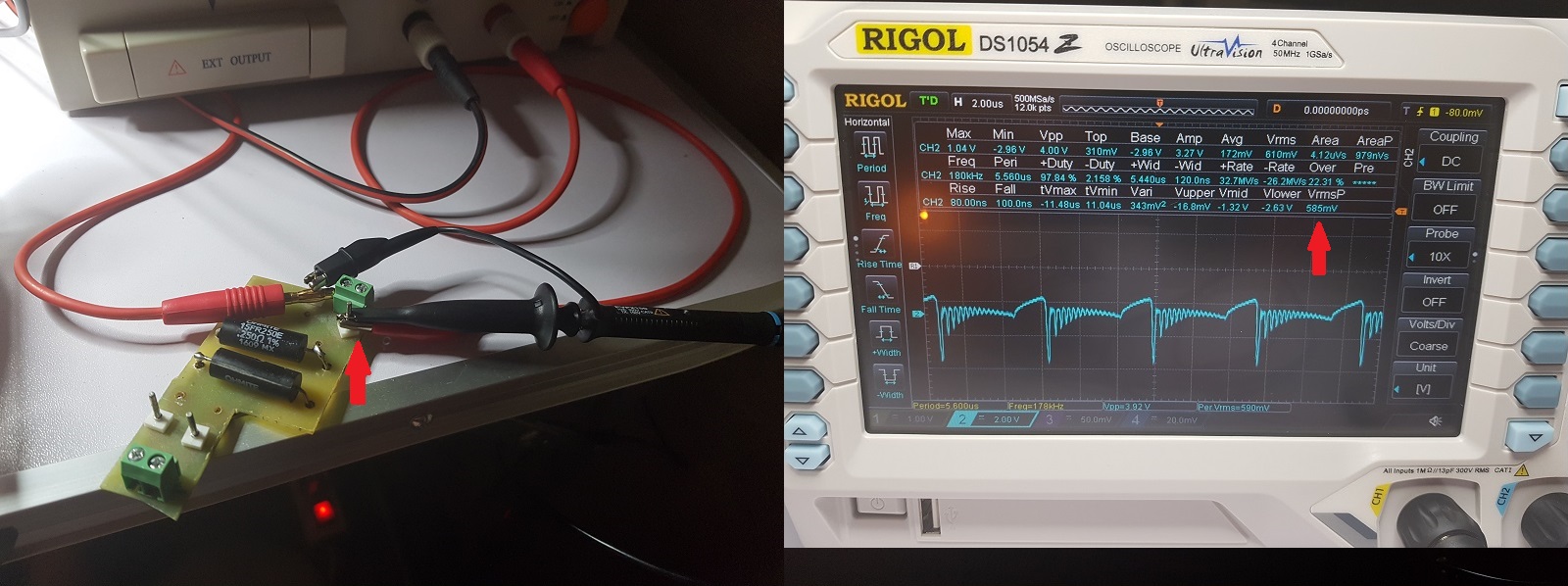
I started some tests and forgot to limit the testing time to 4-5 minutes as usually, analyzing the scope I forgot about the limit and the MOSFET and its radiator in the MOSFET driver got excessively hot. So the last IRFP250N I had in the driver is gone:

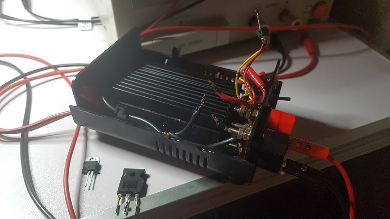
As no electronics store was open today (Sunday) and I didn't had another spare MOSFET I couldn't do anything about this.

So I decided it's time to start working on upgrading the MOSFET driver's cooling system, to make it active using the two coolers I bought some months ago but I always postponed to make this upgrade.

This upgrade is work in progress, this is how it will look like:

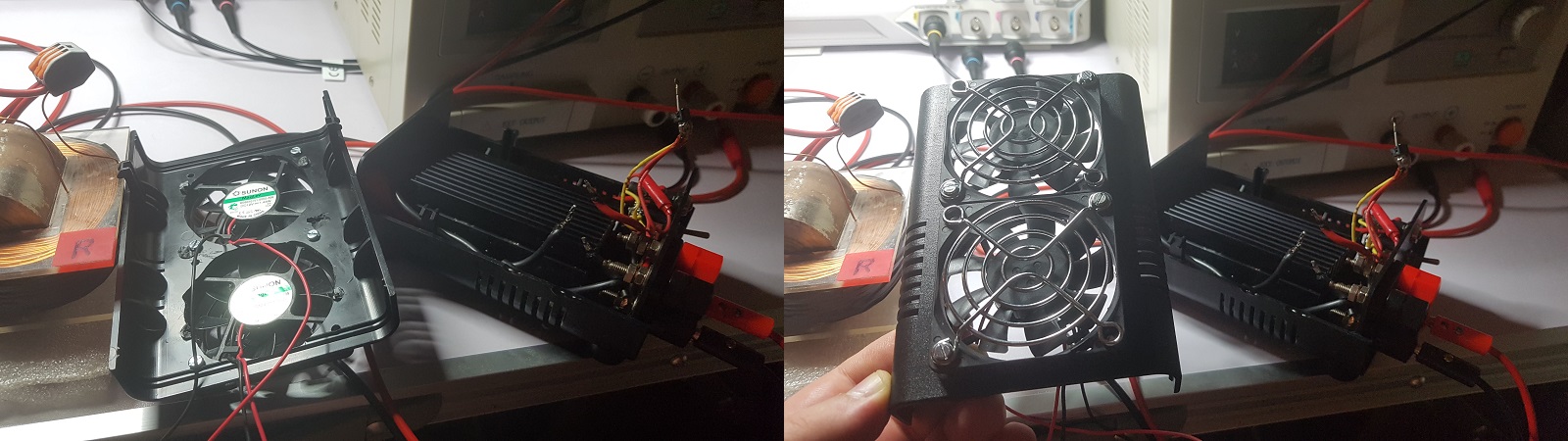
They will be powered separately (to avoid any interference with the circuit, I don't want ZPM to try also to send power back to the coolers too) using a small 12V/1.2A transformer and then I'll convert to DC using a GBU406 bridge-rectifier.

Something like this:

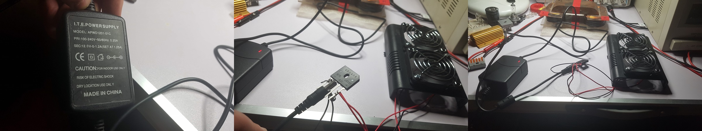
Probably I'll add also a electrolytic capacitor even if coolers seems to work fine without it...

So until I find some time to go buy some IRFP250N MOSFETs, install them in the driver and finish this upgrade I'm not able to continue the experiments, I'll try to do all these if I find some free time during this week.

But even if i wasn't able to do experiments today there is a good thing about what happened, with this upgrade to active cooling system, if it will be efficient enough, hopefully I'll be able to do experiments without needing to stop every 4-5 minutes to let the MOSFET driver to cool down before running another experiment.

"If you want to find the secrets of the universe, think in terms of energy, frequency and vibration."
Nikola Tesla
  • Liked by
  • Inception
Vidura posted this 09 September 2019

Hey Fighter, Sorry about that lost MOSFET. As you can see on some of the scope shots you have voltage spikes reaching nearly the maximum rated voltage of the irfz250, which is 200v. It can possibly avalanche and overheating due to this condition. Although that it is possible that the behaviour of the ZPM could change , I would give it a try with a higher voltage rated MOSFET. Possibly the heating issue can be avoided, and a more reliable operation achieved. Regards Vidura.

Vidura

  • Liked by
  • Inception
Close