Romanian ZPM (Zero Point Module)

  • Topic Is Locked
  • 3.5K Views
  • Last Post 12 February 2023
  • Topic Is Solved
Fighter posted this 07 February 2023

This is the imported thread (from the old aboveunity site) about my ZPM:

For references I will keep the original posting date for every imported post.

Note: This thread is public, everyone can see it, even the visitors which are not members here.

For the posts made by former aboveunity members which are not members on our site I'll use a member placeholder named UndisclosedMember.

Regards,

Fighter

"If you want to find the secrets of the universe, think in terms of energy, frequency and vibration."
Nikola Tesla
  • Liked by
  • Jagau
  • Inception
Vidura posted this 25 August 2019

Hey Friends, You are doing great work all, thank you for sharing your experience, please take in account that sometimes the Google translation are not at all accurate, specially in certain languages. In the English text I couldn't find any offence or demand in the posts. Regarding the measurements, I personally have had some experience with results slightly above cop1 , which have proofed wrong after alternative testing. It is not an easy task with such an unconventional device, and with high frequency currents. We should be a bit carefully to take the accuracy of any measurement techniques as granted, at least when the difference between in and output is not to very much. I have managed that my Amcc cores will be resent to Argentina, so hopefully soon I will be able to join with some experiments with the setup. Regards Vidura

Vidura

  • Liked by
  • Inception
Fighter posted this 25 August 2019

Hi Vidura.

It's not like that, as you can see in the previous screenshots not everyone is sharing, see the ZPM replication powering a 220V light-bulb ? But he still have "doubts" and talk about "measurement errors" ? Right...

Some just take and don't give anything back. And we wonder why we are in this mess on our planet.

He didn't came with any data to support his doubts, didn't saw any oscilloscope screenshots with measurements or anything else showing different results. What can I say, I also can go to anywhere in the forum and start talking about "measurement errors" and talking about doubts.

Sorry about this, I'll just stop my replies to him here and move on because I think I owe an answer to @solarlab

P.S.: I'm glad you could "recover" your Metglas cores and also I'd be happy if you can join the ZPM research, if you need any clarifications about the experiments I presented here I would gladly provide them, feel free to ask 🙂

"If you want to find the secrets of the universe, think in terms of energy, frequency and vibration."
Nikola Tesla
  • Liked by
  • Inception
Fighter posted this 25 August 2019

@solarlab no worries about being a bit lost, we're working with kind of exotic devices here...  

From my point of view ZPM passed the first stage that I call "overunity stage" even if the COP is just 1.1, not as big as I estimated initially based on DC source's readings.

At the end of this stage I think it's appropriate to make a summary and this summary I think would be an answer to your questions.

First, just some background information.

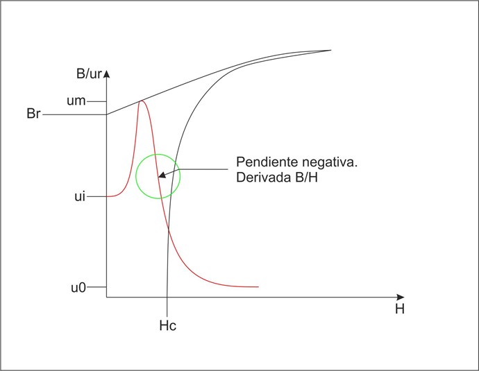
The basic experiment which can provide some information about the phenomenon involved in ZPM is The MrPreva Experiment.

Let's think for a moment about ZPM. Out current physics say this device shouldn't behave like it does. Two asymmetric coils producing opposing magnetic fields which partially annihilate each-other, isn't ? When a pulse is coming on input the smaller coil annihilate half of the magnetic field of the bigger coil (turns ratio is 1:2), isn't ? What's remaining is just half of the magnetic field produced by the bigger coil. Nothing else. According to current physics all what this device should do is to take all the power from the DC source and consume it without any use and the result should be just a small pulsing magnetic field which I doubt would be able to power 2 x 12V/55W light-bulbs like it actually does.

What we actually found is kind of not matching what our current physics says.

While ZPM is able to power (not fully but the light is still very strong) 2 x 12V/55W light-bulbs:

And the test below is with 2 x 12V/35W halogen light bulbs, as a temporary solution to avoid burning the table I put them on a testboard so they don't stay on the table but for now I can't test with them more than 2-3 minutes because for sure the plastic from the testboard will start to melt; the last image shows the luminozity of these two halogen lights when the lights in the room are turned off:

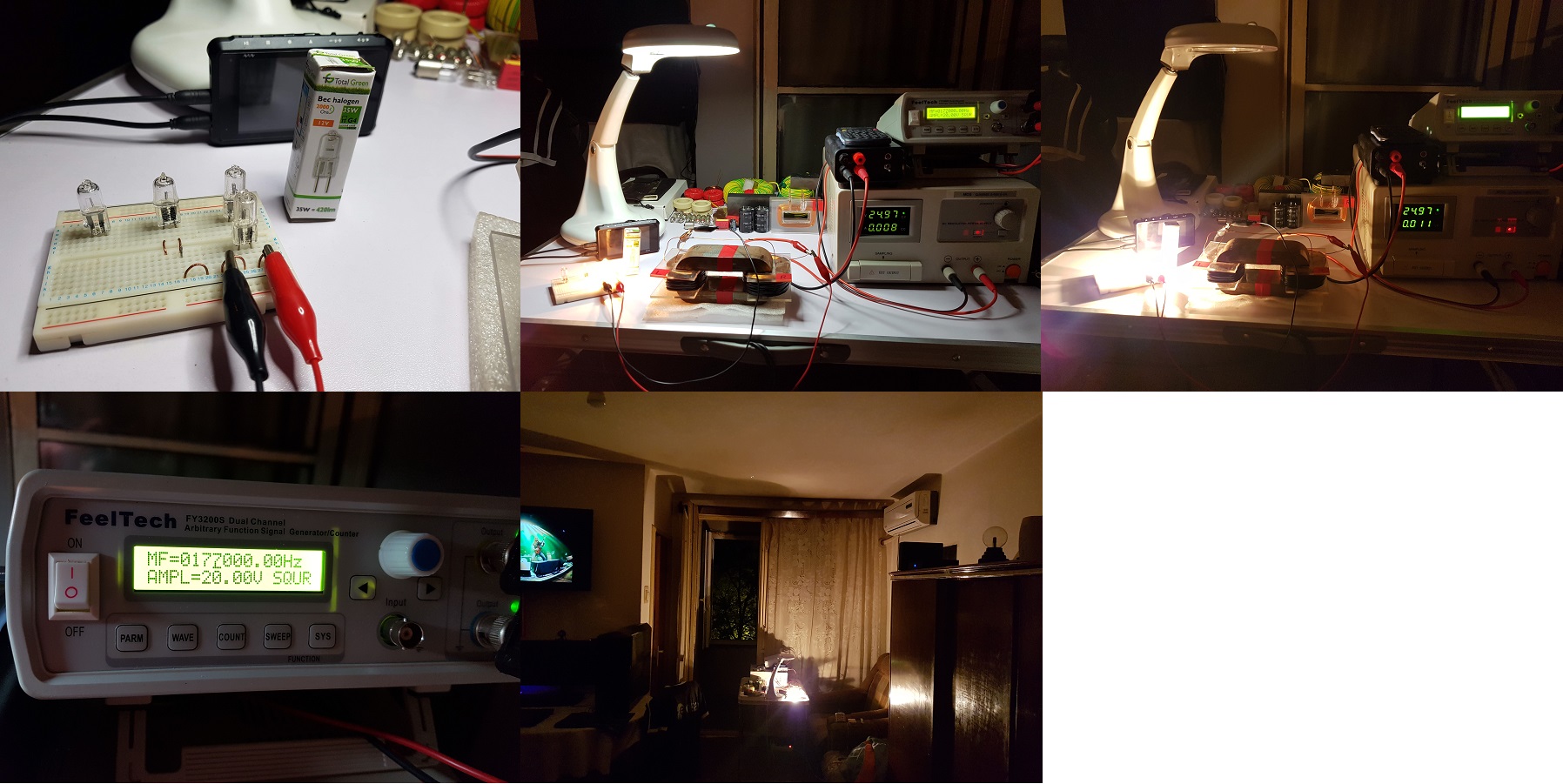
in the same time it "sees" the DC source as another load and is sending power back to it which (in my opinion) may be another explanation of DC source's "confusion" and its readings since a DC source is manufactured just to provide power not to receive power back:

My Friends,

In the below image, we see two numbers with a red line above them:

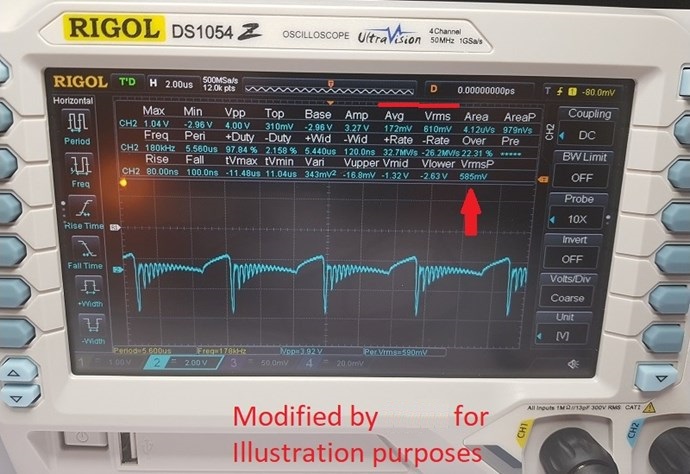
Both numbers are very different! Average or Mean: 172mV and Vrms or Voltage Root Mean Square: 610mV.

Importantly, we have a DC Power Supply! Direct Current meaning one way only! At lease if one is running a Linear Load like a Light Globe!

All Current below the faint turquoise line I have drawn in here:

is Negative Current, its below the Zero Graticule Line of the Probe measuring it.

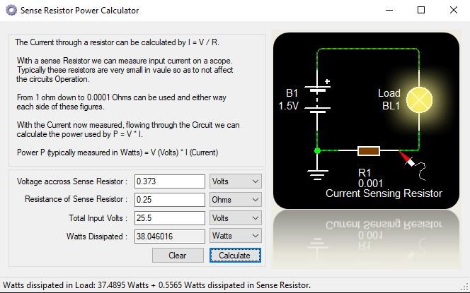
The Root Mean Square is 610mV across a 0.25 Ohm Resistor, this is approximately: 59.512 Watts input to the ZPM.

At the same time the Scope is saying we have 172mV across a 0.25 Ohm Resistor, this is approximately: 17.082 Watts input the ZPM.

Both figures cant be right! So in this case which one do we trust?

We know Power is coming back at us, the ZPM sees the Source as a Load! The ZPM is trying to Power its load, being the Power Supply.

So what do we have? What are the facts?

  1. 172mV across a 0.25 Ohm Resistor, 0.688 Amps, approximately: 17.082 Watts input the ZPM.
  2. 610mV across a 0.25 Ohm Resistor, 2.44 Amps, approximately: 59.512 Watts input to the ZPM.


NOTE: RMS is always positive, it does not give an indication of the direction of power.

Now, I ask others to correct me if I am wrong!

You should use Mean, which is an integration ( Addition ) of the instantaneous power readings ( each sampling point on your screen ) over as many Cycles you have on your screen, which is time, which yields total Energy for this time interval.

This is because your DUT is Non-Linear, and your Source is DC, the DUT sending Power back to Power the DC Source!

With a Linear Load, and an AC Source, you should use RMS most of the time.

What else did we found ?

Well, seems the wave we read on ZPM's output is very similar to what we see on Graham Gunderson's device output (thank you Cd_Sharp for noticing it) which may indicate that his device was using (partially or entirely) a similar concept:

And here it's something which Cd_Sharp noticed, when using the 12W/55W light-bulb the waveform is looking very similar to Graham Gunderson's device waveform:

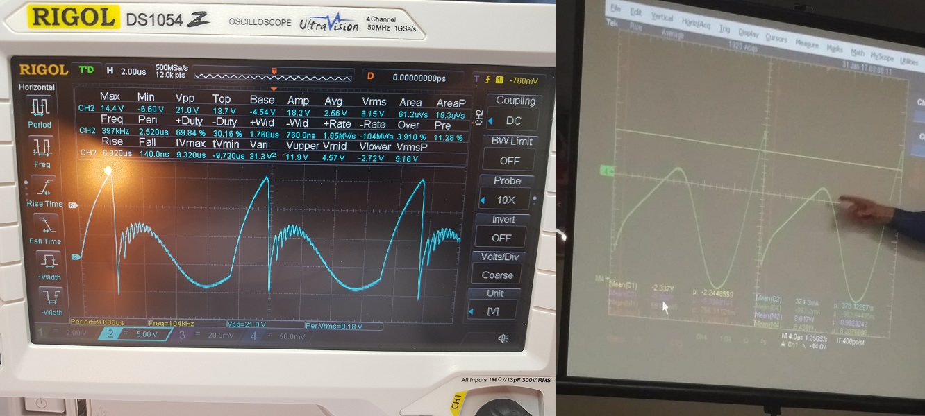
Another thing we found is that on ZPM's output seems to be present some kind of high-frequency standing wave which have some strange effect - there is a 36Vpp voltage difference in the same output wire measured at the point where it's connected to ZPM coil and at another point where (the same wire) is connected to the light-bulb's pin:

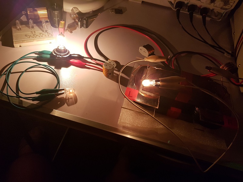
Also you remember that before going to vacation I posted here a photo about a anomaly where the device seems to power preferentially the light-bulbs put on its output ? Like in this image where a 12V/5W light-bulb placed directly on device's coils is illuminating stronger than another 12V/5W light-bulb connected after a 12V/55W light-bulb ? This photo:

I wanted to see what's going on on the output so I connected one channel from the oscilloscope directly on device's coils and another channel on light-bulb's pins as following:

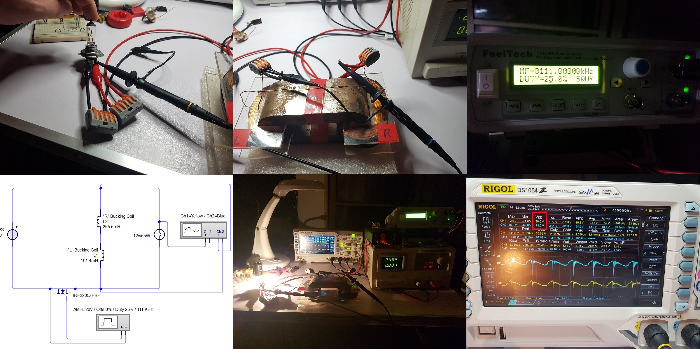
Blue channel is connected directly on ZPM's coils while the yellow channel is connected on the light-bulb's pins.

So I didn't measured the current but I measured the voltage only. As you can see (marked with red rectangle on the image of the oscilloscope's screen) on the same wire there is a Vpp difference of 36 volts between its beginning and its end. I didn't knew it's possible to have voltage difference in the same wire when its length is just 30-40 centimeters.

The only explanation I can find about this anomaly is related to those mysterious standing waves as Vidura noticed:

Hey Fighter and all, The effect that the light bulbs on different connected points (or different wire length) have unequal luminosity is a sign for standing waves at high frequencies. Comparable with Tesla's experience when he shorted a transmission line at one point with a thick copper bar and had at another point of the line light bulbs lit.

Well, maybe I missed something from this (summarized as short as possible) ZPM presentation but I think it provides a general idea of what we're dealing with.

I don't know about you but while experimenting with ZPM I found these anomalies and its behavior strange enough to pursue studying it.

Now the fact that is (even slightly) over-unity (COP 1.1) in my opinion demonstrate that it's worth working on improving it further:

Hey Fighter,

You have my Vote!

Purely Resistive Load, no phase angle to worry about! Figures look good!


Input:


Output:


Well done! Good work Fighter!

You have "Generated" a full: ‭3.574784‬ Watts above your Input for a COP: ‭1.09396‬

Sorry, I exceeded the 10000 characters limit for a post, I'll create a new post and continue there... 🙂

"If you want to find the secrets of the universe, think in terms of energy, frequency and vibration."
Nikola Tesla
  • Liked by
  • Inception
Fighter posted this 25 August 2019

About the physics involved here it's not my specialty (I'm a software developer) but as it contradicts some of the rules of our current standard physics I think the explanations are actually related to quantum physics which also contradicts our standard physics (see particle entanglement phenomenon). I'm just guessing here but I think opposing magnetic fields at high-frequency create "holes" in the zero-point / quantum/ aether field, however we choose to call it, a field which is present anywhere in the universe. And just like when we create a hole in the water, that field is equilibrating those "holes" and that movement create extra-energy which is collected by all the over-unity devices. Of course, opposing magnetic fields is just a way to accomplish that, there are other kind of devices doing this in other ways but even there magnetic fields are involved, they're using electromagnets or permanent magnets. But as I said physics is not my field of expertise and I don't intend to pursue the direction of explaining theoretically what's happening in these devices, that's physicists work when they will decide to wake up and get their heads out of sand. My project and my goal are for building a device having COP higher than 3 so it can power itself and in the same time power a let's say 100W load.

Now what about the next stage, where it will go from here ?

I call this new stage "enhancements stage". Measuring COP should become more precise and should be done in real-time so I can work on fine-tuning. Measuring let's say the output using light-bulbs luminosity is not a option anymore like it was in the previous stage 🙂

Right now I'm working on a filter which hopefully would be a solution for my "confused" DC source and its readings. The assumption is DC source's readings are messed up because of high-frequency noise coming back to it from the MOSFET driver and /or ZPM. If that's the case maybe this filter suggested by Vidura will solve the problem:

A suggestion for a simple and good filter for keeping out interference from our measuring devices. The values of the components are not at all critical, but may need some adaptation for the expected frequencies. Ceramic decoupling  and tantalium caps for the smaller values perform better. The meters could be replaced by a scope as well.

Regards Vidura.

But if (as I suspect) the DC source's "confusion" is created by the fact that ZPM is sending power back there would be another approach: I need to figure out if ZPM is really using that big capacitor from the DC source as its own component and find a way to stop it doing that because I want that power to be put to use on the real output therefore this would increase the COP. Would be nice if by doing that I would get COP closer to 2. Also by doing that I would prepare a later stage where ZPM should be separated from the DC source and made to work on batteries. But doing this will require a lot of time and experiments.

Another step is to make a real-time reliable power measurement system for both input and output using current-sensing resistors and connected on that system two channels of the oscilloscope, maybe additionally some digital and also analog measurement instruments. That would require a lot of work to build and especially to calibrate to make sure the readings are correct all the time.

Having this real-time measurement system would allow me to fine-tune ZPM while having real-time COP shown because right now I'm finding the optimal frequency by increasing-decreasing it by 1KHz steps but for fine-tuning I should go to 1Hz steps. This hopefully would allow to have some significant increase of the COP but I estimate it will take a lot of time to ensure the system's readings are reliable in any conditions and considering I don't have too much free time it will take a while.

Another step would be to explore other coils configurations. That could significantly increase the COP as I'm sure I didn't matched from the beginning the optimal coils configuration of this device, I just used 1:2 ratio but there could be other ratios which could have great impact on COP as you can see from these posts:

Hello everyone.

I think I know how it is possible to extract energy from the vacuum.
It turns out that the magnetic permeability behavior
It has a region in which it is negative!
As if it were a tunnel diode, it also has it.
Only in this, we draw the current from the source and its
behavior as an amplifier is real.
Because the negative region in ferromagnetic materials
It is expressed by permeability, it interacts with the vacuum.
Here the graph of their behavior.

This image is just a sample of how permeability changes
depending on the current through the inductor that makes up the system,
It is merely illustrative.
That is why there are two operating points, one is static and depends on the
load, and other dynamic and depends on the frequency.
I continue with the experiments that prove that the OU is possible, it is still a
Hypothesis not a theory.
It would not violate any thermodynamic law because it extracts the energy of an entity
We still don't understand.

@Fighter.
I still do tests to understand your experiment, but everything has to do
with magnetic permeability and standing waves.
The turns ratios must be quadratic because the inductance is.
This means that the turns ratios will be the root of 0.75, 0.5 or 0.25 of lambda for
one of your inductors N2 = SQR (n) N1, where n is one of the previous numbers.

Thank you all in advance.
YoElMiCrO.

@YoElMiCrO: In my current setup "L" coil has approx. 150 turns and "R" coil approx. 300 turns.

N2 = 150 turns, N1 = 300 turns.

So N2 = 0.5 * N1 = SQR(0.25) * N1, it matches the case where n = 0.25.

Other configurations would be:

1. N2 = SQR(0.5) * N1 = 0.70 * 300 = 210 turns for coil L where n = 0.5; Lturns / Rturns = 210/300;

2. N2 = SQR(0.75) * N1 = 0.86 * 300 = 258 turns for coil L where n = 0.75; Lturns / Rturns = 258/300.

Of course N1 can be increased or decreased too, I just calculated for N1 = 300 turns where I want to keep "R" coil as it is now and just modify "L1" coil.

Interesting, very interesting... If your hypothesis is confirmed we may have a formula to design any configuration for this device. I wonder which case is better in terms of efficiency.

So this would be a draft of this new "enhancements stage". At least how I see it right now, I'm sure as I progress other steps could be added or some steps could be removed, it's not something which could be planned precise from the beginning, it's research and experiments and could lead anywhere. Sorry it was a long post, it took me 2 hours but I hope it answered your questions and with this occasion I've made a summary of the current status of the ZPM and I drafted a plan to what I intend to do in the near future. Depending on the free time I will have it may take a while to do this.

"If you want to find the secrets of the universe, think in terms of energy, frequency and vibration."
Nikola Tesla
  • Liked by
  • Inception
UndisclosedMember posted this 25 August 2019

Hi Fighter,

EXCELLENT dissertation, thank you very much for taking the time to clearly explain!

Will have to review it some more in detail, especially the Standing Wave hypothesis.

Gorchilin's site has a bit on fractional wavelength standing waves that he has observed - which somehow, in the back of my mind, seems to correlate ??? Interesting... Page is hard to find so it's linked below:

Slow Magnetic Waves (4 pages) - Gorchilin [ http://gorchilin.com/articles/coil/magnetic_wave?lang=en ]

Quite interesting indeed!

SL

  • Liked by
  • Inception
Fighter posted this 25 August 2019

Thank you sir 🙂 I hope this review is offering some clarifications but keep in mind I couldn't include all the details in it, the other details can be found in the previous posts from this thread.

"If you want to find the secrets of the universe, think in terms of energy, frequency and vibration."
Nikola Tesla
  • Liked by
  • Inception
Atti posted this 25 August 2019

Fighter !

I think you are mad at me.


-I'm sorry, but this is a hypersilicon iron core. Not Metglas!
-I think iron of the same size and material would be important for accurate replication. Perhaps I have the opportunity.Also, if the exact size were available, it would be associated with the exact thread speed. But that doesn't mean anything, because I can ruin anything! The real conclusion is that as many people as possible would have to do the same experiments.
- My coil layout is not perfect. In the next I will try.
- The bulb is 24V 40W, but this is irrelevant in this case!
-If I'm done with your assignment, I'll come here and tell you the measurement should be any result!
-I think those who share their opinions here with others are happy to do so. They don't demand anything, they don't ask for anything.


I think sometimes I do better if I stay silent.

  • Liked by
  • Inception
UndisclosedMember posted this 25 August 2019

Hey Guys,

I think it is really a case of "Think Simple" on this as complicating it in any way will make for unnecessary confusion!

Think: Accelerate Charge, the rest will follow.

@Atti: If I may recommend, perhaps a replication, another side by side supporting thread, of Fighters work? Prove to yourself simple things work best!

  • Liked by
  • Inception
Fighter posted this 25 August 2019

Hi Fighter,

EXCELLENT dissertation, thank you very much for taking the time to clearly explain!

Will have to review it some more in detail, especially the Standing Wave hypothesis.

Gorchilin's site has a bit on fractional wavelength standing waves that he has observed - which somehow, in the back of my mind, seems to correlate ??? Interesting... Page is hard to find so it's linked below:

Slow Magnetic Waves (4 pages) - Gorchilin [ http://gorchilin.com/articles/coil/magnetic_wave?lang=en ]

Quite interesting indeed!

SL

This is actually very interesting !

I will need to find some free time so I can read it carefully and understand the details presented there but even taking a quick look now I find some things quite intriguing there !


"If you want to find the secrets of the universe, think in terms of energy, frequency and vibration."
Nikola Tesla
  • Liked by
  • Inception
Fighter posted this 25 August 2019

I just found a detector of standing waves on that site. How cool is that ?

I'm putting the link here for later references, I will need this at some point:

http://gorchilin.com/articles/coil/indicator?lang=en

Also a visual simulator of standing waves:

http://gorchilin.com/calculator/longline?lang=en

"If you want to find the secrets of the universe, think in terms of energy, frequency and vibration."
Nikola Tesla
  • Liked by
  • Inception
Close