Romanian ZPM (Zero Point Module)

  • Topic Is Locked
  • 3.5K Views
  • Last Post 12 February 2023
  • Topic Is Solved
Fighter posted this 07 February 2023

This is the imported thread (from the old aboveunity site) about my ZPM:

For references I will keep the original posting date for every imported post.

Note: This thread is public, everyone can see it, even the visitors which are not members here.

For the posts made by former aboveunity members which are not members on our site I'll use a member placeholder named UndisclosedMember.

Regards,

Fighter

"If you want to find the secrets of the universe, think in terms of energy, frequency and vibration."
Nikola Tesla
  • Liked by
  • Jagau
  • Inception
Fighter posted this 13 September 2019

@Wistiti: No worries about asking. No, I didn't explored that configuration but in the future I intend to try ZPMs with different coil ratios including 1:1.

For what we know for now coils asymmetry is the key for over-unity devices but honestly I would be curious about testing a 1:1 configuration of ZPM, nobody knows until it's built and tested.

Another step would be to explore other coils configurations. That could significantly increase the COP as I'm sure I didn't matched from the beginning the optimal coils configuration of this device, I just used 1:2 ratio but there could be other ratios which could have great impact on COP as you can see from these posts:

Hello everyone.

I think I know how it is possible to extract energy from the vacuum.
It turns out that the magnetic permeability behavior
It has a region in which it is negative!
As if it were a tunnel diode, it also has it.
Only in this, we draw the current from the source and its
behavior as an amplifier is real.
Because the negative region in ferromagnetic materials
It is expressed by permeability, it interacts with the vacuum.
Here the graph of their behavior.

This image is just a sample of how permeability changes
depending on the current through the inductor that makes up the system,
It is merely illustrative.
That is why there are two operating points, one is static and depends on the
load, and other dynamic and depends on the frequency.
I continue with the experiments that prove that the OU is possible, it is still a
Hypothesis not a theory.
It would not violate any thermodynamic law because it extracts the energy of an entity
We still don't understand.

@Fighter.
I still do tests to understand your experiment, but everything has to do
with magnetic permeability and standing waves.
The turns ratios must be quadratic because the inductance is.
This means that the turns ratios will be the root of 0.75, 0.5 or 0.25 of lambda for
one of your inductors N2 = SQR (n) N1, where n is one of the previous numbers.

Thank you all in advance.
YoElMiCrO.

@YoElMiCrO: In my current setup "L" coil has approx. 150 turns and "R" coil approx. 300 turns.

N2 = 150 turns, N1 = 300 turns.

So N2 = 0.5 * N1 = SQR(0.25) * N1, it matches the case where n = 0.25.

Other configurations would be:

1. N2 = SQR(0.5) * N1 = 0.70 * 300 = 210 turns for coil L where n = 0.5; Lturns / Rturns = 210/300;

2. N2 = SQR(0.75) * N1 = 0.86 * 300 = 258 turns for coil L where n = 0.75; Lturns / Rturns = 258/300.

Of course N1 can be increased or decreased too, I just calculated for N1 = 300 turns where I want to keep "R" coil as it is now and just modify "L1" coil.

Interesting, very interesting... If your hypothesis is confirmed we may have a formula to design any configuration for this device. I wonder which case is better in terms of efficiency.

"If you want to find the secrets of the universe, think in terms of energy, frequency and vibration."
Nikola Tesla
  • Liked by
  • Inception
  • AlteredUnity
Fighter posted this 14 September 2019

This is not directly related to ZPM but today when adding some new files to my free-energy archive I did read again some documents containing Bearden's correspondence.

There is a paragraph saying:

Now we strongly call attention to something else in conventional electrical engineering. If one merely places a charged capacitor on top of a permanent magnet, so that the E-field of the capacitor is at right angles to the H-field of the magnet, that silly thing will sit there and pour out EM energy indefinitely, perfectly freely, by the conventional Poynting equation S = E X H which has been optimized.

That's how "difficult" it is to get extra energy flow from the vacuum. It's a piece of cake, and can be done for a dollar - anywhere, anytime in the entire universe. One can easily extract as much EM energy flow as one wishes.
That silly little capacitor and magnet already invalidates everything we were told in university about how difficult it will be to ever extract usable EM energy from the vacuum. There is also a form of the Poynting equation for a single dipole, as just the charged capacitor or the permanent magnet. It's already known and accepted.
Yet engineers believe that they have to input all the EM energy to a circuit that one can get in the circuit to use. That's not only wrong, it's a bald-faced lie after more than 100 years of that dogma (the Poynting theory dates back to the 1880s).

Did anyone tried this simple experiment ?

Could it be so simple ?...

"If you want to find the secrets of the universe, think in terms of energy, frequency and vibration."
Nikola Tesla
  • Liked by
  • Inception
UndisclosedMember posted this 14 September 2019

Hey Fighter,

We may be better to start a new thread on this subject?

Ref: Tom Bearden

I have done a little work here, have a little to share, but its not as good as your current path!

What you have is way better in my humble opinion. šŸ˜‰

  • Liked by
  • Inception
Fighter posted this 15 September 2019

Hi UndisclosedMember,

Oh, I don't intend to stop ZPM research but that paragraph was so intriguing that I was thinking about it all day (while working on my MOSFET driver repair and upgrade, I will add another post about this later).

What were the results of your experiment ? Did it shown any anomalies ?

Of course I don't expect this to power too much load but if it can power at least one LED (or more) I think this would would be better (at least as a self-sustaining demonstrator device) than Akula's lantern.

If you don't mind when you have some time I think sharing your experiment could pave the way for another category of devices and projects. Even if it failed in the beginning maybe it can be continued.

A new thread about this would be great ! Every idea and experiment counts.

It's intriguing enough that I feel this could be a secondary research project I could work on.

Thanks,

Fighter

"If you want to find the secrets of the universe, think in terms of energy, frequency and vibration."
Nikola Tesla
  • Liked by
  • Inception
Fighter posted this 16 September 2019

So yesterday and today I worked on replacing the MOSFETs in my driver and also upgrading the cooling system (making it active with coolers).

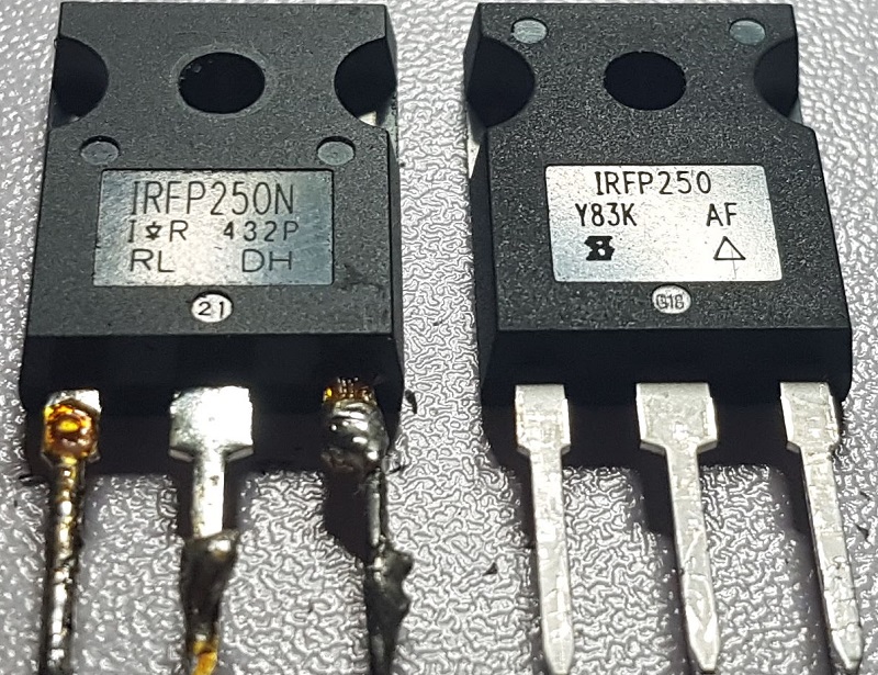
Unfortunately the electronics store I'm buying from don't have IRFP250N anymore, so I bought few pieces of IRFP250:

The active cooling system seems to be its job well, before I needed to make pauses after 5 minutes while doing experiments to give time to the MOSFET driver to cool down, now I let it run about 30 minutes and when checking the radiator from inside of the driver it was just warm, not extremely hot like it happened before after just 5 minutes.

Below are few images made during the MOSFETs replacement and cooling system upgrade:

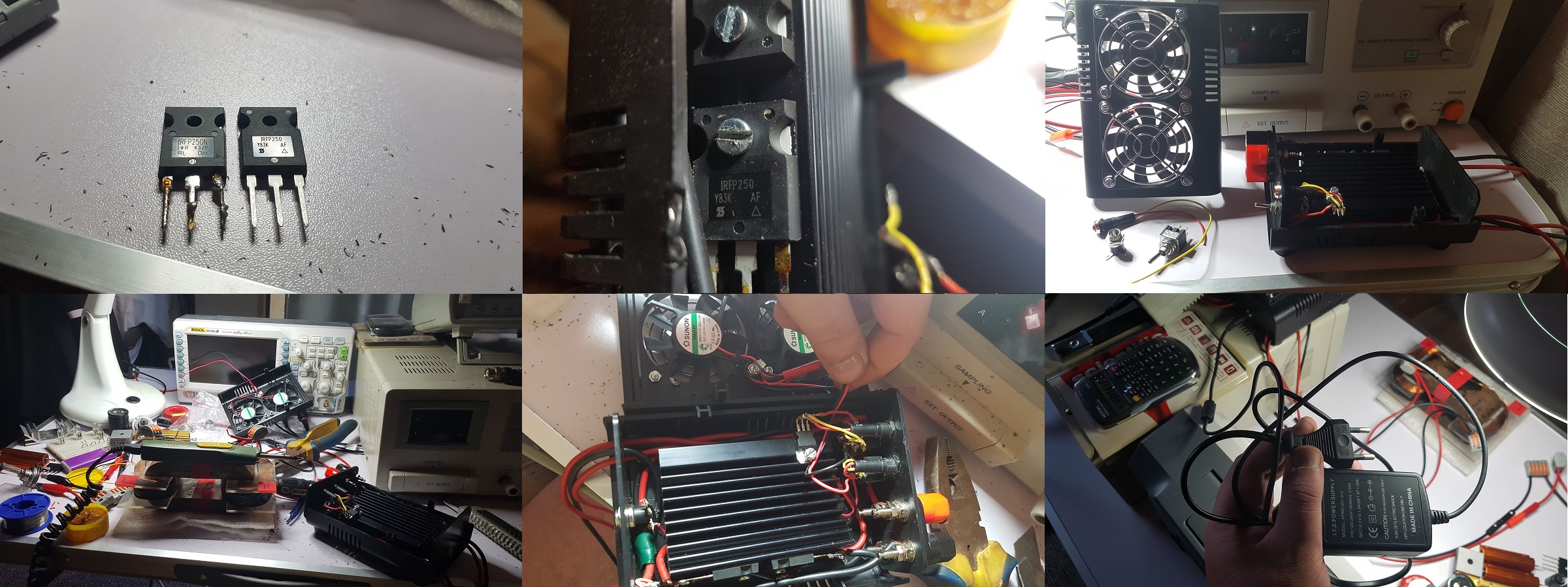
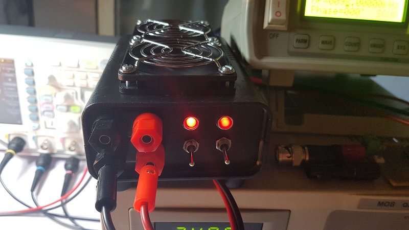
The coolers are powered separately from a 220V/12V DC power adapter so they don't interfere in any way with the experiments. Basically (as you can see in the previous images) the 12V DC power is coming to the backside of the MOSFET driver and through a jack the power is going to the front panel to a second switch which allows me to turn on or off the coolers. When that switch is turned on it's powering a second red LED (visual indicator showing me when the coolers are running) and also the two coolers.

So this is how it looks now:

to analyze the data and the behavior of ZPM with different parameters.

About the new MOSFETs, considering the switching timing differences between MOSFETs even between those from the same series I was afraid that changing them could affect ZPM's behavior and even would be possible to not be able obtain on output its specific waveform.

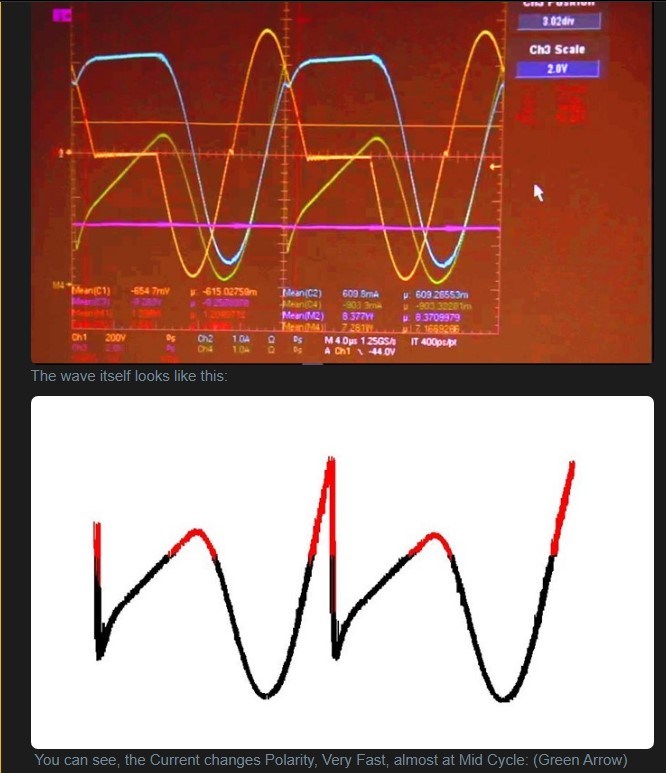
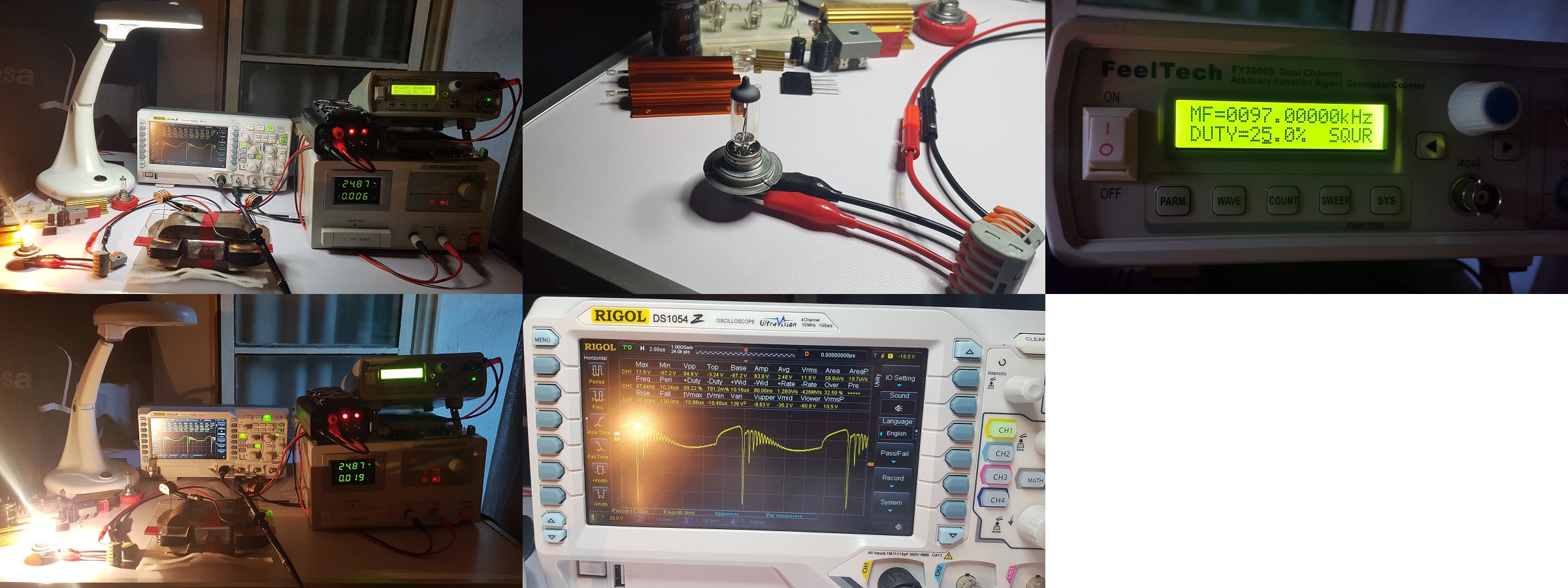
Fortunately the waveform is still there, this is a test with a 12V/55W light-bulb:

and this is a test with 2 x 12V/55W light-bulbs:

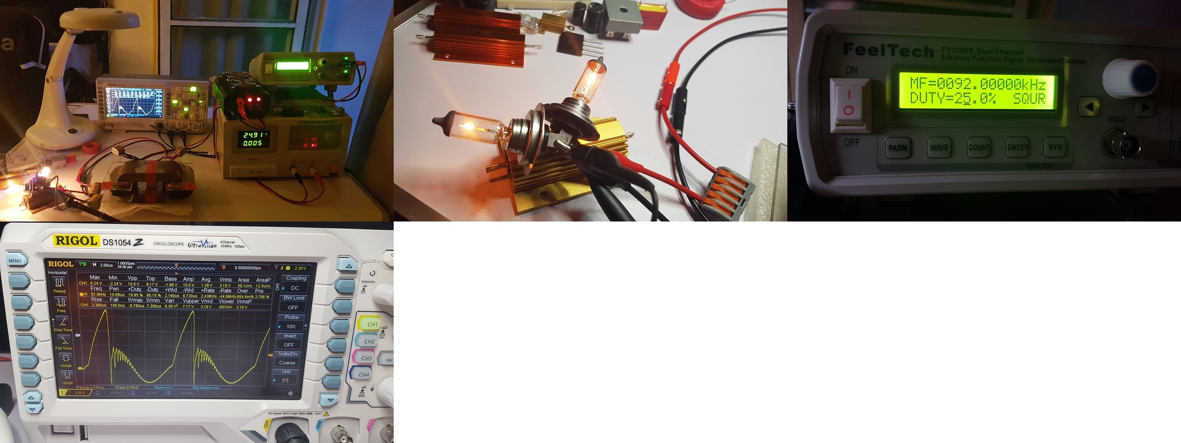
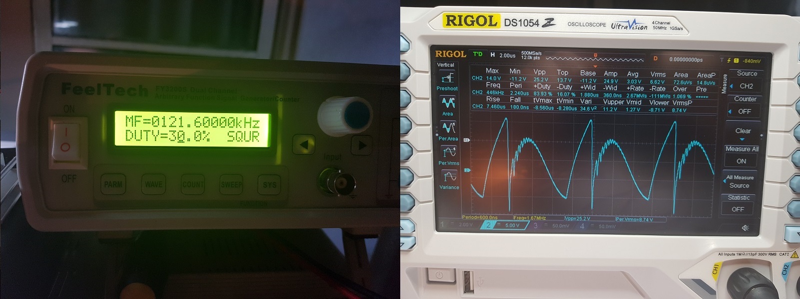
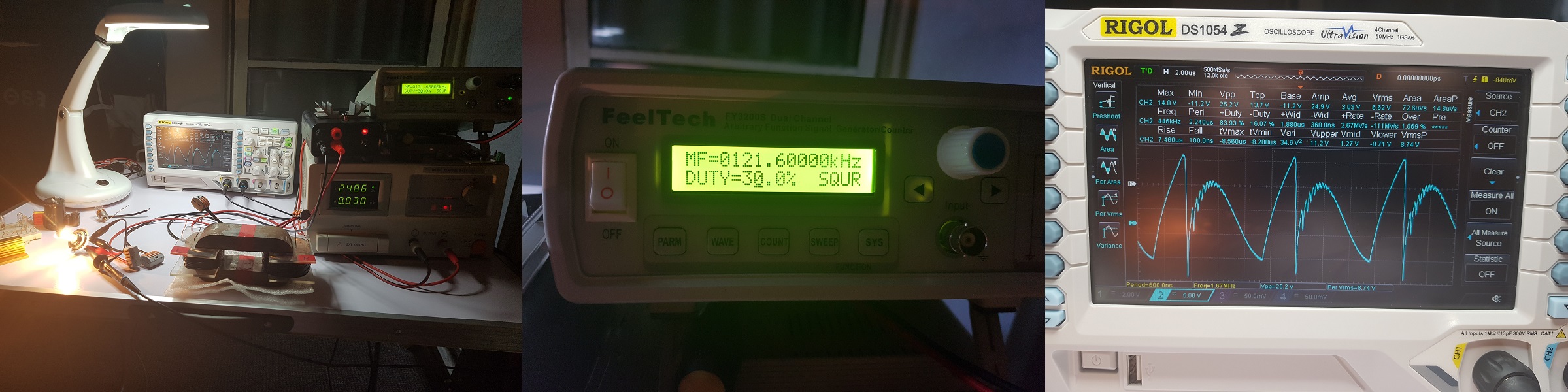
But there is a downside of this, the switching performance of the new IRFP250 MOSFETs seems to be lower, they moved the optimum frequency down with about 24 KHZ, now the optimum frequency for a 12V/55W light-bulb on output is going down to just 97 KHz (check in previous images) while before with IRFP250N the optimum frequency was 121 KHz (below is an older image):

Also you can notice the output waveform for 12V/55W light-bulb is different now, not like it was before with the older MOSFETs.

I don't like this as I know ZPM like to run at frequencies over 100 KHz, probably I will replace the current MOSFETs with the ones from Cree/WolfSpeed when they will arrive and I'll have some free time.

Except this, the next thing I will work on when I'll have some free time is to start using Vidura's PowerSwitches commanded by my signal generator, on this I'm still reading the tutorial and the details posted by Vidura.

I'm thinking to put some of those Cree/WolfSpeed MOSFETs on Vidura's PowerSwitches too, but first I'll learn to use them as they are now commanded by my signal generator.

"If you want to find the secrets of the universe, think in terms of energy, frequency and vibration."
Nikola Tesla
  • Liked by
  • Inception
Jagau posted this 17 September 2019

Hey fighter
excellent work
the scopeview are very close of Gunderson


Jagau

  • Liked by
  • Inception
  • AlteredUnity
cd_sharp posted this 18 September 2019

Guys, I double checked, the current sensing resistors Fighter is using are not the cause of the problems I've seen. They are reliable. My mistake.

If you know how to build such a device and you're not sharing, you're a schmuck! - Graham Gunderson

  • Liked by
  • Inception
Fighter posted this 18 September 2019

@Jagau: Thanks. Yes, it seems the waveform we read on ZPM's output is very similar to what we see on Graham Gunderson's device output (thank you Cd_Sharp for noticing it) which may indicate that his device was using (partially or entirely) a similar concept - the bucking coils. Recently in a conversation with Cd_Sharp I found out a detail I missed, seems Gunderson's device was using for switching MOSFETs made by Cree. As a coincidence I have a shipment from US (still waiting for customs to release it) containing some C2M0160120D-ND MOSFETs made by Cree/WolfSpeed and recommended by Vidura. They have superior switching technology and are made to work at high frequencies, I think they could make a difference and enhance ZPM's behavior.

@Cd_Sharp: Thanks, no worries, it happens to all of us when making research... šŸ™‚

"If you want to find the secrets of the universe, think in terms of energy, frequency and vibration."
Nikola Tesla
  • Liked by
  • Inception
UndisclosedMember posted this 18 September 2019

Hi Fighter,

Pretty sure you'll be impressed with the SiC's - they open up a whole new dimension!

BTW - we've had a few (Littlefuse ones) that "leaked a bit of smoke" on us. Much shorter "short circuit" survival times than the older technologies. Your probably aware of the quirks but here's a Link to a straight forward article anway:

https://www.powerelectronicsnews.com/technology/evaluating-1200-v-sic-mosfets-robustness-under-short-circuit-conditions

Happy Pulsing! šŸ™‚

SL

  • Liked by
  • Inception
Fighter posted this 19 September 2019

Hi UndisclosedMember, thanks, I didn't knew about this weak point.

Well, I'll try to not short-circuit them if they are so sensible, hopefully a few from those 6 will survive... šŸ™‚

"If you want to find the secrets of the universe, think in terms of energy, frequency and vibration."
Nikola Tesla
  • Liked by
  • Inception
Close