Fighter
posted this
23 August 2019
Thanks guys !
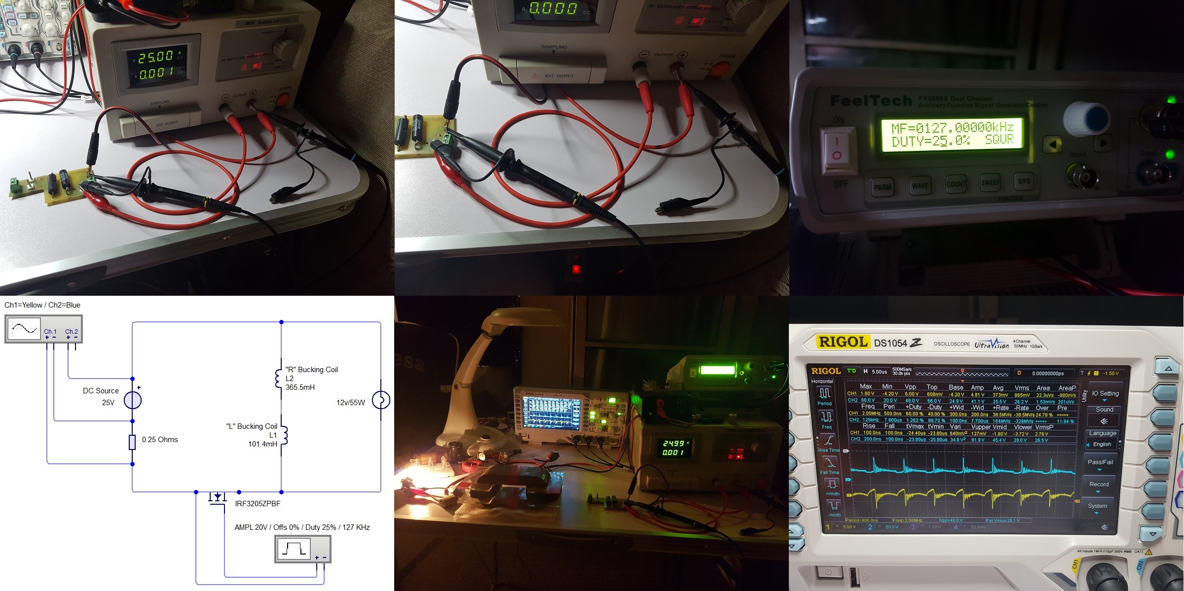
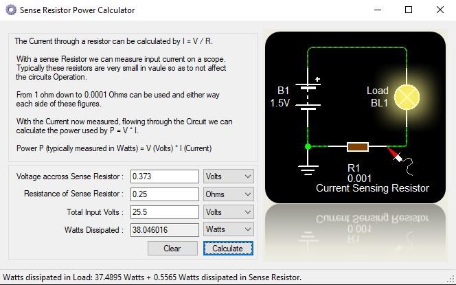
You have "Generated" a full: 3.574784 Watts above your Input for a COP: 1.09396
It would look much better if I "convince" ZPM to not "see" the DC source as a load and to try to power it up 🙂 At this point I have no idea how I can accomplish this, I need to think about it.
I would like very much to see a input measurement with a RC filter in between the instruments(or scope) and the ZPM. For comparison if the results mach and also if the ZPM perform correctly if fed from a filtered input-capacitor array.
When you are tuning the module you should monitor the Avg current and Voltage on the input, to find the point where you got the effect with a minimal inputpower.
I would try to prepare that when I get more time, possibly in weekend. But when I tried last time to put a choke coil on input's positive wire (before going to vacation) the ZPM didn't worked at all, the DC source entered in auto-protection mode, the voltage stabilizer which powers that LED in the MOSFET driver was burning and smoking and I had the impression the MOSFETS themselves didn't felt very well, they were heating up quickly so I did shutdown the experiment. The voltage stabilizer (powering that LED) is destroyed again 🙂
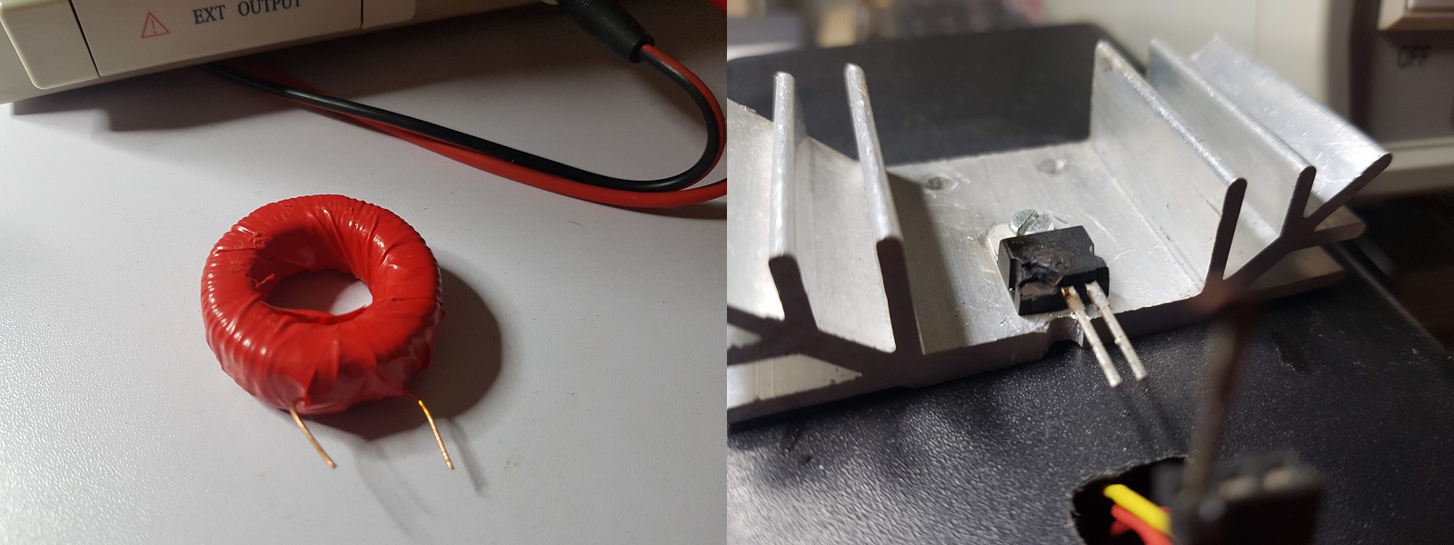
The choke-coil has 80 turns of 0.8mm wire on ferrite core.
I think it's related to ZPM trying to send power back to the DC source, seems it doesn't like choke coils, but it's just a guess...
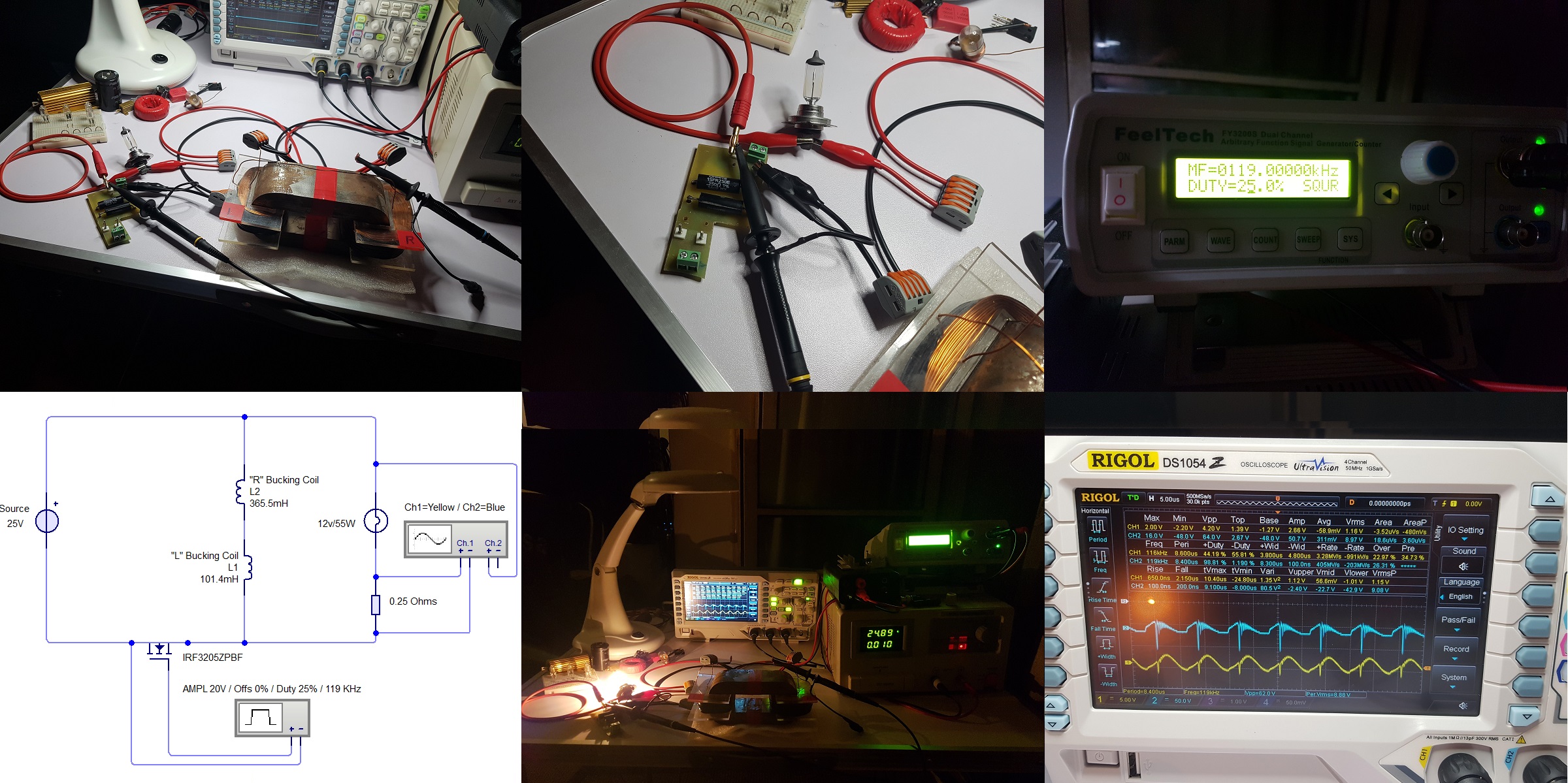
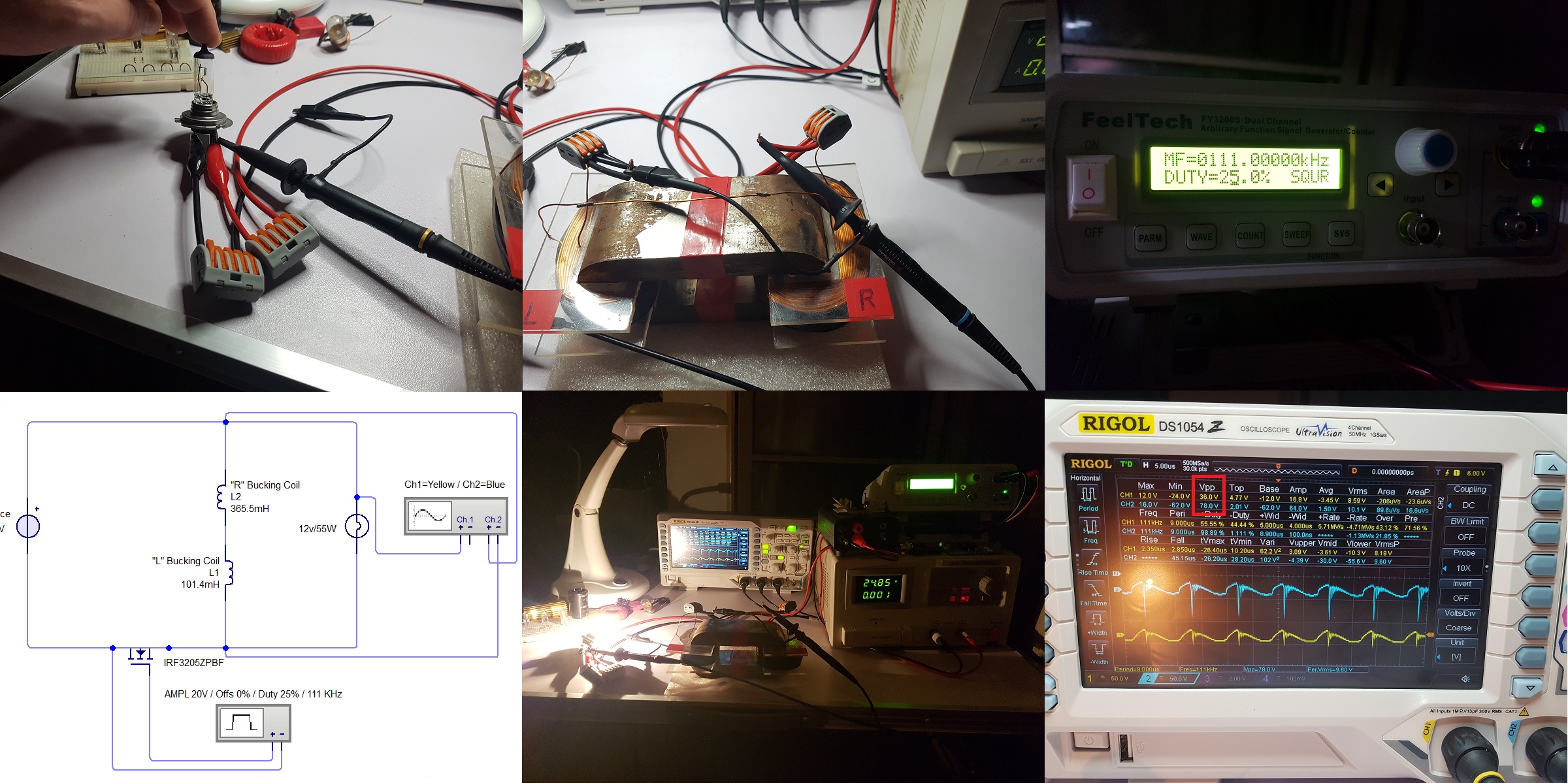
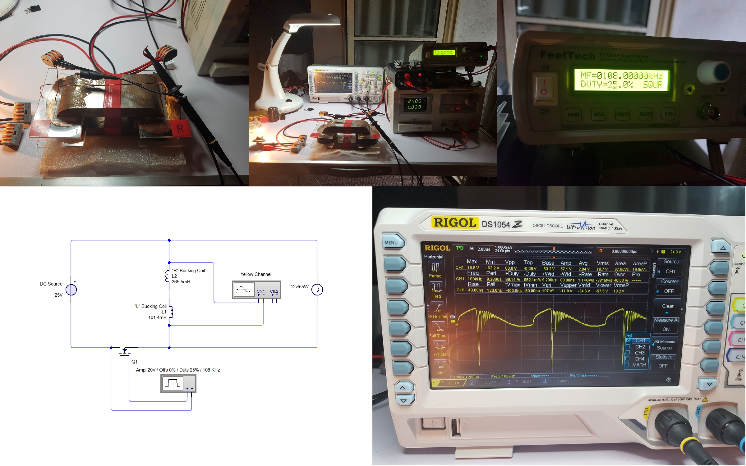
Also I have a question, is there any conventional explanation why introducing that current-sensing resistor in the output makes Vpp and Vrms drop ? I already know that the voltage is higher on ZPM's coils than on light-bulb pins (standing waves effect) but could the resistor have a role in the voltage drop too ?
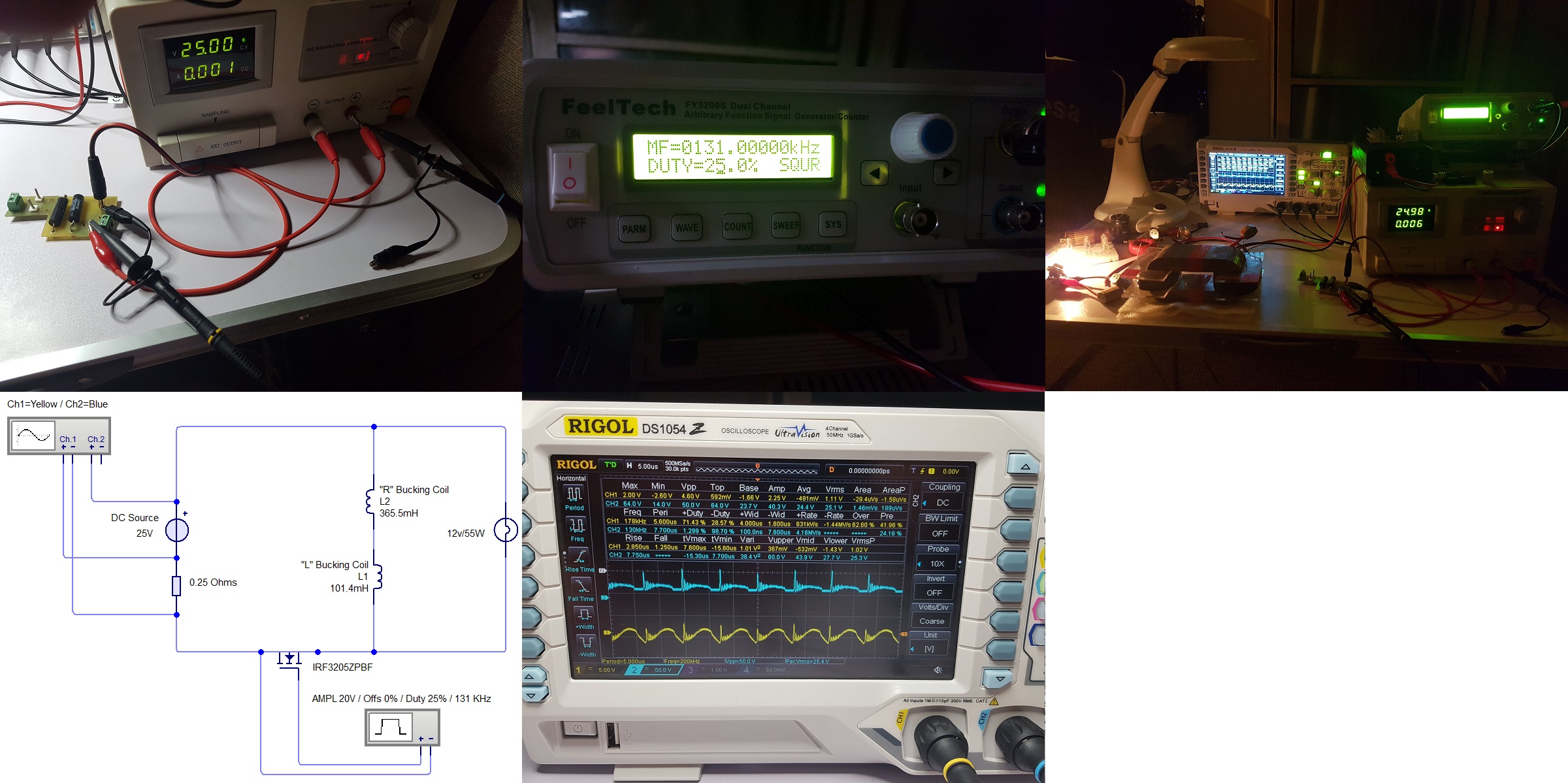
Take a look at the next image and values highlighted with red rectangles, one is the output measurement made yesterday and other is just oscilloscope (without resistor) put directly on ZPM's coils:
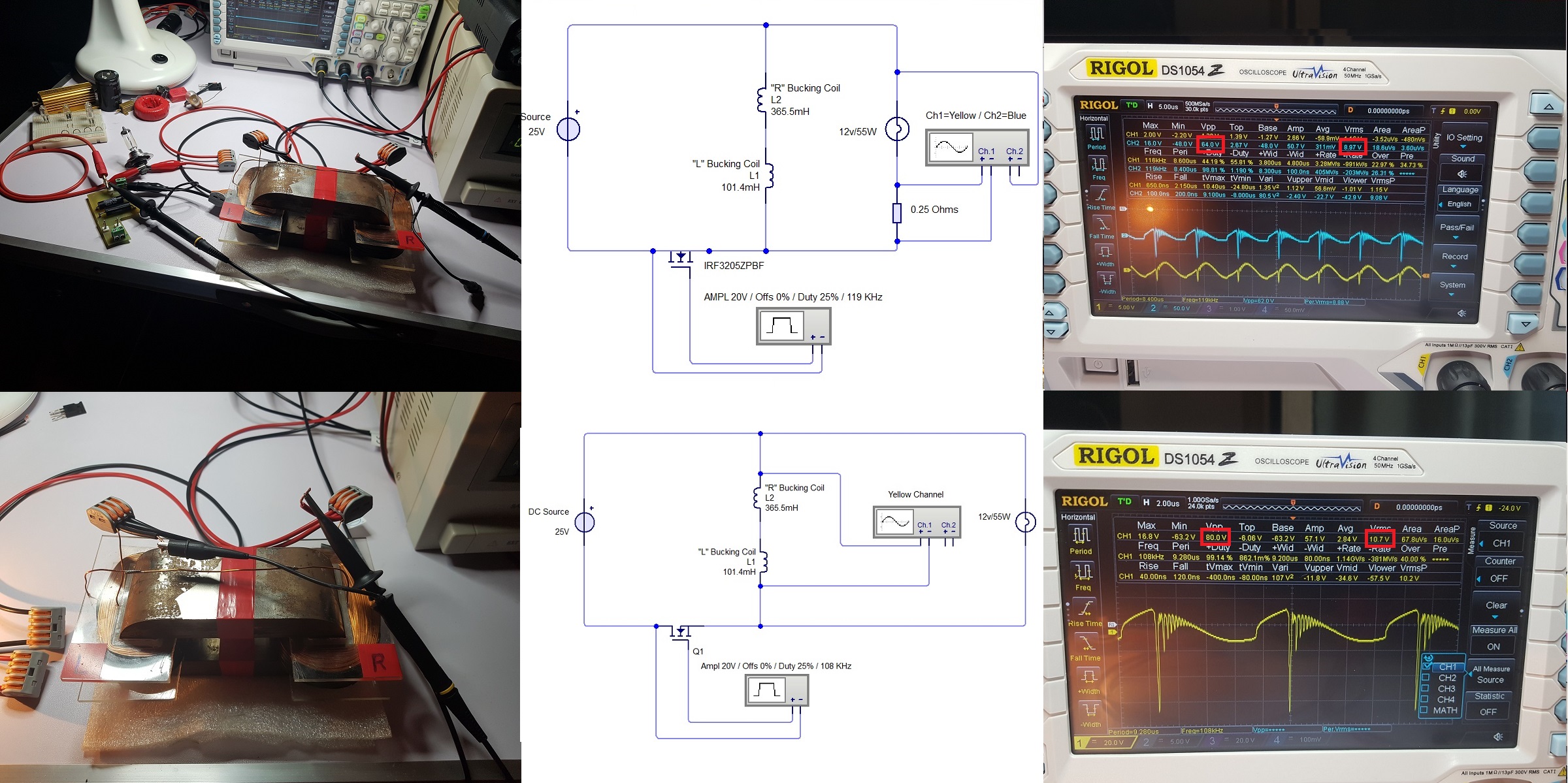
It's a 16Vpp voltage drop !
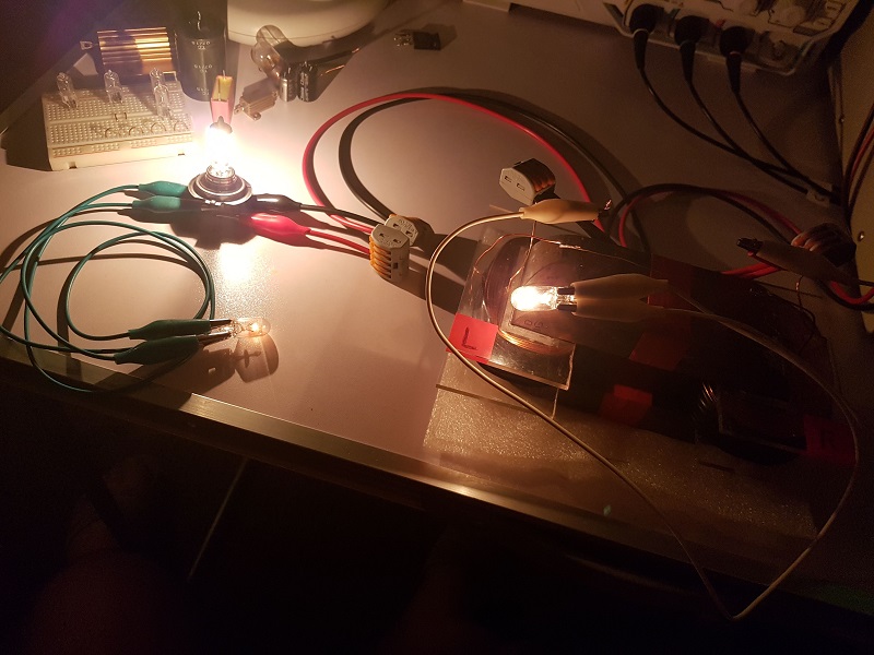
Based on what I observed in experiments until now maybe I should put the current-sensing resistor directly on ZPM's coils and measure output again there ? And also I'm thinking about to put the light-bulbs directly on ZPM's coils and eliminate those output wires which seems to degrade the output power ?
But again, how useful the output power would be if it can't be transmitted properly through wires, if it's degrading when using wires on output ?.. A lot of questions and decisions to make regarding further experiments and enhancements...
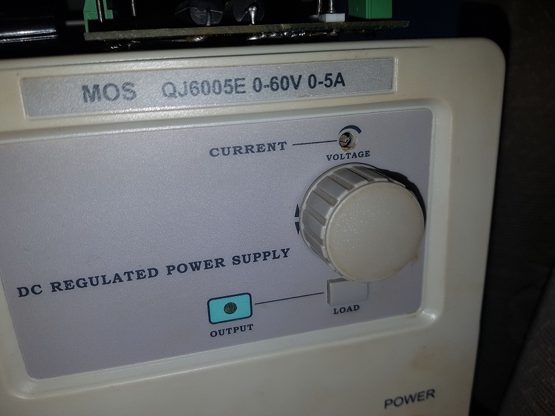
Edit: I have also another question which I wanted to ask but I always forgot: is there any scenario when a physical current limiter in a DC source can be tricked so the source is actually providing more current than the limit set on that current limiter ? I'm asking because I tried before several times to set the current limit to just 20mA while powering the ZPM and the source didn't entered in auto-protection mode as it usually does when testing the same scenario with let's say a 200mA light-bulb powered by the DC source. With ZPM the source doesn't enter in auto-protection mode but it does with that 200mA light-bulb.
This is the current limiter on my DC source:
| "If you want to find the secrets of the universe, think in terms of
energy, frequency and
vibration." |
|
|
Nikola Tesla |