Romanian ZPM (Zero Point Module)

  • Topic Is Locked
  • 3.5K Views
  • Last Post 12 February 2023
  • Topic Is Solved
Fighter posted this 07 February 2023

This is the imported thread (from the old aboveunity site) about my ZPM:

For references I will keep the original posting date for every imported post.

Note: This thread is public, everyone can see it, even the visitors which are not members here.

For the posts made by former aboveunity members which are not members on our site I'll use a member placeholder named UndisclosedMember.

Regards,

Fighter

"If you want to find the secrets of the universe, think in terms of energy, frequency and vibration."
Nikola Tesla
  • Liked by
  • Jagau
  • Inception
Vidura posted this 26 August 2019

Hey Fighter yes the links for gorchillins site have been posted by aloha some time ago, there's actually interesting information. I have made some of this magnetic wave detectors the first time in a older video with a opposing coils configuration on a ferrite bar and the scope connected instead of the LEDs, then I made others with LEDs on a small inductor. A good and simple tool to visualize standing wave effects.

Vidura

  • Liked by
  • Inception
UndisclosedMember posted this 27 August 2019

But if (as I suspect) the DC source's "confusion" is created by the fact that ZPM is sending power back there would be another approach: I need to figure out if ZPM is really using that big capacitor from the DC source as its own component and find a way to stop it doing that because I want that power to be put to use on the real output therefore this would increase the COP. Would be nice if by doing that I would get COP closer to 2.

Hey Fighter. - I am Glad you decided not too make any changes too your circuit yet, -   because its better that you decide when too try any of my observations, rather than i wait,  and decide when i mention it...

Also, my estimation of the above issue is that, - you and your meter is correct.  - the linear behavior is hard too argue with, it looks very convincing and well above COP 3. - i thought it was likely well above 10, even 20+...  and mabee not much room for improvement at that voltage.  . interesting it failed with batteries. - is your troublemaker capacitor ;=D LOW ESR or Electrolyic, or BiPolar normal, or "can" style ?.   thankyou.

Atti. i would love too see your experiments also, - it seems it can be done very cheaply. - certainly an $900 core is out of my price range - i am going too try and work with ferrites, and chinese cores. - and hopefully iron, - i have several iron transformers from old medical equipment in the 30-40 kg range ;=). ,

also mate, - dont stop talking, you mean well, that is plain too see. ....  just like when a person responds in panick too a forum post ( at the thought of offending a person accidentally ), - i sure have done it too.  peace and love !

Patrick1

  • Liked by
  • Inception
Atti posted this 28 August 2019

Hey Patrick!
I don't think an effect only works with super substances. That's why I chose hyperersil iron. It's at home.
However, the current setting is not correct (the coils are not on the edges) and should be redone.
Be calm when you have a new setting I'll make a video about it.
The currents measured at the current setting are incorrect. Only the light current measured on the coil is not very high on the coil. Only a few.
Therefore, the coils give almost no reaction to the circuit. Where there is current there must also be a magnetic field, where there is a change in magnetic field there is a voltage. Probably too many coil turns for such a high frequency.Or, the power supply should be raised.
For example, this measurement of coil and bulb current is not seen in Fighter's assembly.
I think it is likely that magnetic resonance is here.
But irrelevant, I just wondered.

Years ago I did an experiment with a similar setup. But the point is in it.Two opposing magnetic fields.However, the data of the coils are the same there.

This setting caused a knocking noise on a small radio. Even with magnetic shielding.
 Like J.L. Naudin in the TEP circuit. I think YoEIMiCrO may have noticed this. But he'll let us know.

I'll probably expand the measurement.
But now I have little time to deal with it.

  • Liked by
  • Inception
YoElMiCrO posted this 29 August 2019

Hello everyone.

@Fighter.
With this circuit I designed is that I am testing my replica of your ZPM and
now for WET with a small modification.
It is based on PLL, to facilitate frequency adjustment.
The frequency range is between approximately 25 to 150KHz
for the published circuit, but changing the PLL capacitor found
between pins 6/7 you can modify this frequency, it also has a resistor in the
pin 12 which modified sets the minimum working frequency.
The maximum possible frequency will be 1.4MHz.
I think it can help you, here the circuit drawn by hand again, sorry.

Here an image of the PCB terminated with said circuit.

Thank you all in advance.
YoElMiCrO.

  • Liked by
  • Inception
Fighter posted this 29 August 2019

Hi guys, sorry for not answering, I have a lot of things to do at work, I'll answer in weekend.

"If you want to find the secrets of the universe, think in terms of energy, frequency and vibration."
Nikola Tesla
  • Liked by
  • Inception
Atti posted this 30 August 2019

Hi.

The following came to my mind when looking at Fighter's layout.
Voltage returned from PWM powered d.c motor via idle diode.

difference is that there is no opposing magnetic field. (and what if?)


I wanted to do a full measurement against my options.
Obviously not the best!

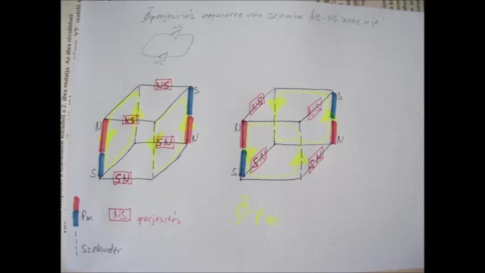
In this configuration, the transformer can withstand 2Tesla max induction of iron.
The coils are on both sides of the iron.
The inductance ratios of the coils can be varied.
Drawing in the video. The magnetic directions are opposite.

It also shows what happens when only one coil is wired.

In this measurement, I was curious about the ratio of inputs to outputs.
Unfortunately, the needle impulse disorders made the whole thing inaccurate.

So I thought I'd skip the resistance current measurement.

An approximate measurement would probably be the DC voltage.
The question is how to put the bulb on DC so that it does not change our circuit.
One-way diodes and capacitors are not suitable.
Diode rectifier performs peak rectification.
It doesn't charge the entire output signal. It just pinches its top, but it does! The rectifier should be one that loads both the positive and negative periods of the current.

Both half-periods are known as doubling the known and shown voltage in the video.
Right now, I thought this was appropriate.
If the two-sided voltage is not the same, it will automatically shift with the rectifier zero.
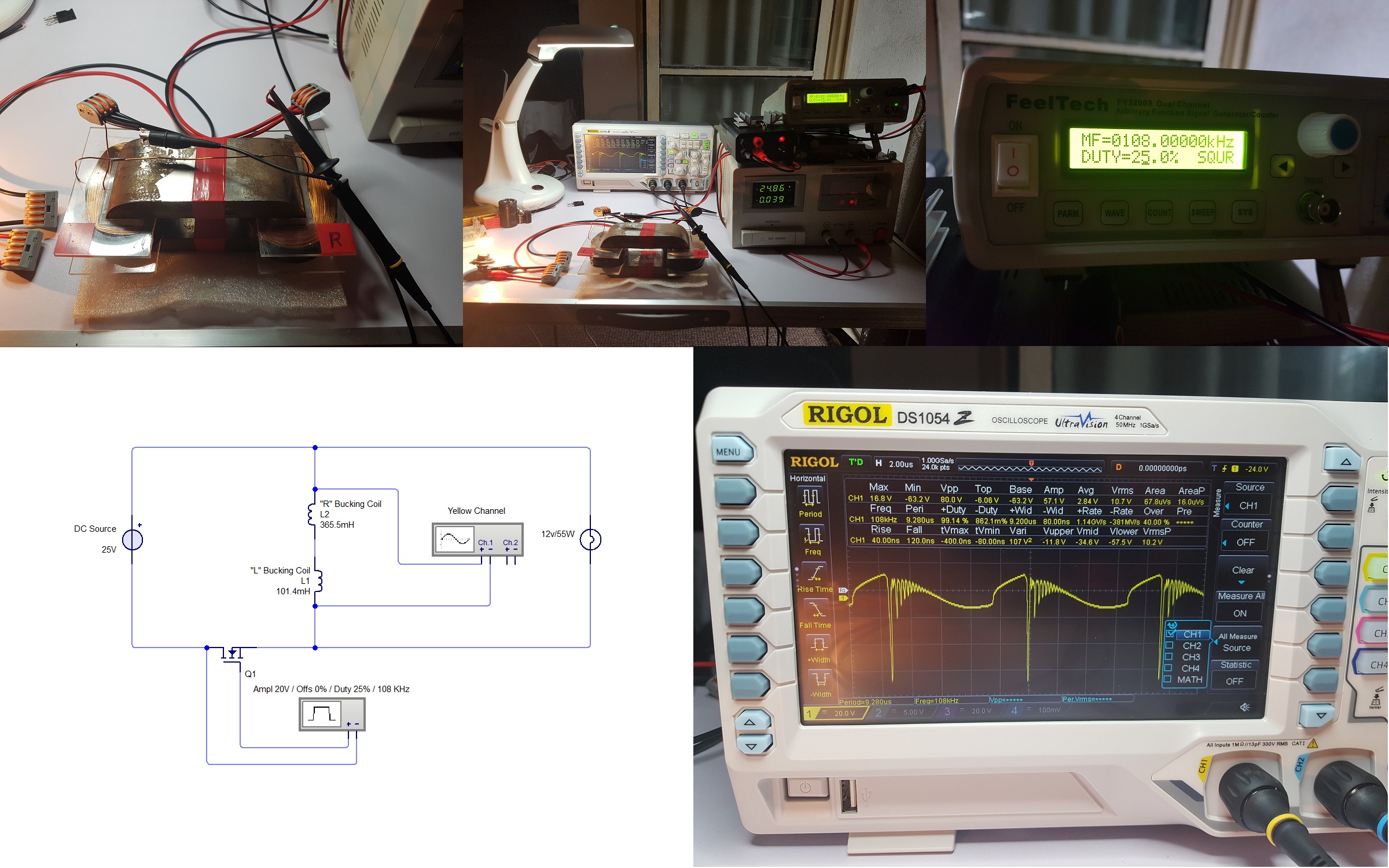
But as you can see it is not perfect, because the shape of the voltage is almost triangular.
It would have been better if I had put the voltage first in an inductive storage and then the rectification from there.

The measurement results are for information only!
But it demonstrates the whole meaning of it.

Special thanks to Vidra for the idea!

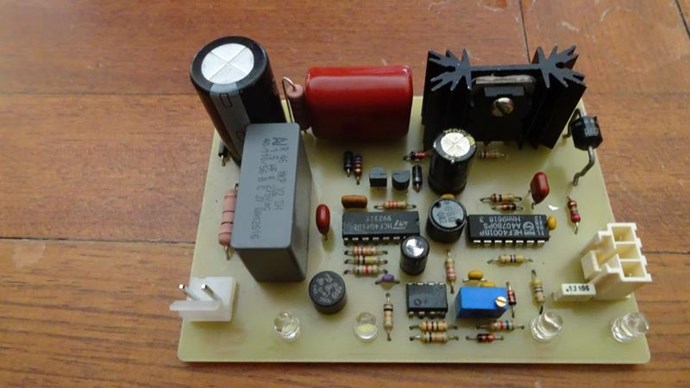
I thought the 4 4700y capacitors connected in parallel to the power supply would handle the interference. But no!

A filter must be placed on the power supply. The difference is clearly visible in the video. The voltage of the FET disturbance is also well discernible.
So proper propulsion must be provided.
That is why measurements should be handled and kept in mind.

Significant energy can flow backwards in the downstream direction at some settings.
This can be measured by simpler (even oscilloscope) power meters as input power. (also due to embarrassment)
The drive is pulsed (10-50%).
Measuring every opportunity.
Then I tried it with the H-bridge.
There has been a lot of change here, but we need to take proper breaks.
The result is the same.


Obviously I did not fully act!
He was running like this at the moment.
I'd be happy for someone else to do some measurement over their capabilities.


Please join me, don't just read the results because I might be lying!

  • Liked by
  • Inception
UndisclosedMember posted this 31 August 2019

woohoo.  usps says my cores are in the country.

in the mean time, i have been having a good struggle with ferrites....  3 steps forwards, 3 steps back...  dan they are hard nuts too crack....  im at risk of feeling stubborn, but i want the stability of using a core, instead of air....    but for consistancy i may be better working with air.....    much too learn as always.  - at least we have enormous magnets too garnish free energy from untill we catch up

  • Liked by
  • Inception
Fighter posted this 05 September 2019

Hi guys, sorry for being silent lately, I just have an unexpected spike of things to do at work and for now I have almost no time to work on the project, I'm waiting for weekend, hopefully I'll have some time to resume the tests.

"If you want to find the secrets of the universe, think in terms of energy, frequency and vibration."
Nikola Tesla
  • Liked by
  • Inception
Fighter posted this 06 September 2019

Hi, that's made by Hitachi Metals, it should have 100% the same characteristics as mine.

Never managed to find out what that label A-17 (on your core) or E-15 (on my core) means but I don't think they are related to characteristics.

Did you checked to make sure the coils magnetic fields are opposing ?

Also did you searched for the optimum frequency (sweep) for your load like I do here ?

At the optimum frequency with your scope put in parallel on output you should see on your scope a waveform like this:

What are you conclusions about COP ?

"If you want to find the secrets of the universe, think in terms of energy, frequency and vibration."
Nikola Tesla
  • Liked by
  • Inception
Vidura posted this 06 September 2019

@Atti,Good that you joined the experiment, interesting information, do you drive the MOSFET directly with the Signal generator? It looks more like an analogue oscillator. The current shunts with non inductive shape is a good idea. I have a bit difficulty to follow exactly the circuit design, a drawing of the complete setup and measurement points would be great . Thanks for sharing your work. Vidura.

Vidura

  • Liked by
  • Inception
Close