Romanian ZPM (Zero Point Module)

  • Topic Is Locked
  • 3.5K Views
  • Last Post 12 February 2023
  • Topic Is Solved
Fighter posted this 07 February 2023

This is the imported thread (from the old aboveunity site) about my ZPM:

For references I will keep the original posting date for every imported post.

Note: This thread is public, everyone can see it, even the visitors which are not members here.

For the posts made by former aboveunity members which are not members on our site I'll use a member placeholder named UndisclosedMember.

Regards,

Fighter

"If you want to find the secrets of the universe, think in terms of energy, frequency and vibration."
Nikola Tesla
  • Liked by
  • Jagau
  • Inception
Fighter posted this 09 September 2019

Hi Vidura, about MOSFET it's not a problem, it happens... I was also thinking to change the MOSFETs but I had the same concern - different switching times, ZPM behavior change etc. I intended to a buy few more IRFP250Ns and to look for others with higher rated voltage to give them a try. Unfortunately the store I'm buying from don't have IRFP250N anymore, the closest I found there are some IRFP250PBF, not sure if they will work the same like IRFP250N (regarding switching times and ZPM behavior), but I'll buy them and I will see.

Also I will look if the store has others with higher rated voltage. Anyway, with IRFP250PBFs or others, as long as I'm not gonna use exactly the same MOSFETs (IRFP250N), I'm prepared for some changes in ZPM's behavior.

Also I need to make a correction here related to the active cooling, now I realized that 12V transformer is actually converting to DC so that bridge-rectifier is useless, it's very late here (5 a.m.) and seems that I'm really tired... šŸ™‚

"If you want to find the secrets of the universe, think in terms of energy, frequency and vibration."
Nikola Tesla
  • Liked by
  • Inception
cd_sharp posted this 09 September 2019

Hey, guys

What is the circuit to test the Current Resistors?

Note: the DC PS is on 0V, no current output.

3 x 10A/75mV current-sensing shunts

That means 1 amp will give you a reading of 7.5mV and 0.1A will read as 0.75 mV, while the scope you have cannot read less than 5mV. You will read the output current more precisely, but you won't be able to read the input current.

I suggest you keep the current sensing resistors, they are good, but they ring at high frequencies. The scope shots you showed are good, you just have to ignore the ringing. That makes it fit in with the asymmetrical regauging even better.

If you know how to build such a device and you're not sharing, you're a schmuck! - Graham Gunderson

  • Liked by
  • Inception
UndisclosedMember posted this 09 September 2019

Hey CD,

Yes, Fighter is right, this circuit is full of what they call parasitic Inductance. This will give you the spikes you are seeing.

For a test on the resistors, you can use a circuit like this:

Keep all leads short, and you should get a nice Linear DC Current reading.

@Fighter, CD is right, although the Current shunts are very nice, they will be hard to measure small currents: I = V / R

At the rated 10 amps and the rated 75mv, we get a resistance of: 0.0075 Ohms. That's a power of 75Watts. You can calculate the numbers here: Ohms Law Calculator.

  • Liked by
  • Inception
cd_sharp posted this 09 September 2019

Guys, a correction, Rigol DS1054Z is able to read down until 1mV.

If you know how to build such a device and you're not sharing, you're a schmuck! - Graham Gunderson

  • Liked by
  • Inception
Fighter posted this 10 September 2019

Hi Atti,

Thank you for joining the research on ZPM and sharing the experiments.

Right now I'm at work but I saw one time your video, I'll watch it more times when I find some free time.

Yes, that's the ZPM's specific waveform, of course it will vary depending on the load but that's the pattern.

About the frequency, when you hear that high-pitch sound from the core it means the frequency is too low, that should not be audible, at low frequency the device is losing its normal behavior, in my case I always try to keep it over 120-150 KHz.

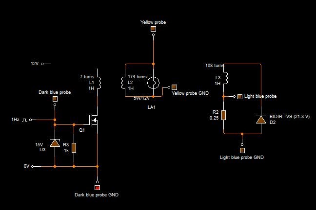
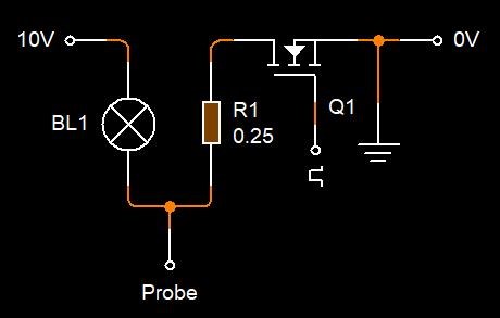
About measurement, the only way to get some accurate measurements is with current-sensing resistors or shunts and with oscilloscope. Don't count too much on that analog ampere-meter, even if you put choke-coils on your source's output the device is still sending power back to the source and that power has high-frequency pulses, the analog ampere-meter is made for DC, it will never be able to give any indication about the current going to the ZPM and receved back from the ZPM, most probably what it's indicating is just the amplitude of the spikes it "sees" in the circuit, not the real consumption.

As I said the only practical way is just the one with current-sensing devices and oscilloscope.

There could be another possible way, to try to convert ZPM's output to DC, I tried it at the beginning but it destroyed a big electrolytic capacitor from one of the channels of my Schotky bridge-rectifier. Another possible problem with this approach could be that introducing a bridge-rectifier on ZPM's output most probably will alter the way the device's coils interact with each other, but this is just a assumption for now as I didn't tried this I'm just thinking about it.

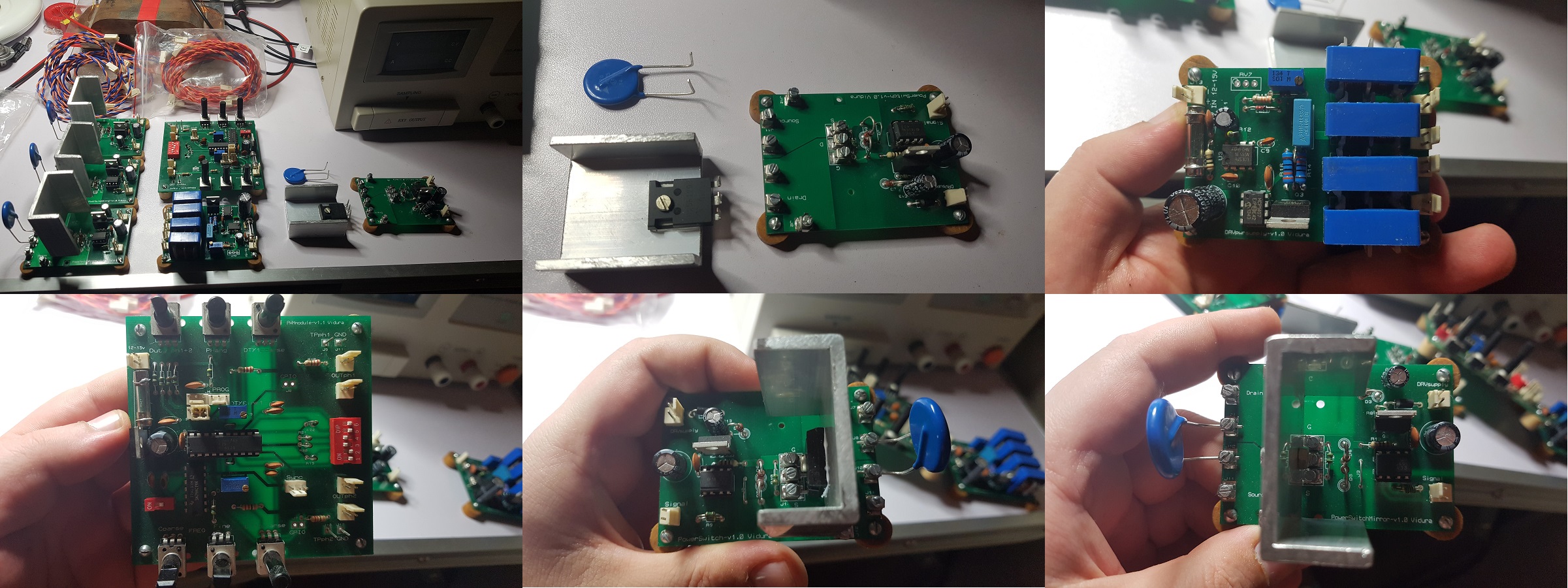
Unfortunately for now my MOSFET driver is out of service, I need to find some free time to put new MOSFETs on it and also to finish the upgrade to a active cooling system; so for the moment I can't run experiments but I'll continue when I'll finish the changes of the MOSFET driver.

About the power of the two light-bulbs, as I said ZPM seems to have some kind of "preferences" about how it powers its loads... šŸ™‚ I don't know how those "preferences" can be influenced but frequency seems to be one of those criteria.

Trying with a grounding connection is a interesting way, I was thinking for a while about it but didn't had time to do experiments on that way, what I see in your experiment seems very interesting.

Thanks again for joining the ZPM research, please feel free to share your experiments with your ZPM here; or if you want you may create a separate ZPM replication thread, depends on how you prefer.

"If you want to find the secrets of the universe, think in terms of energy, frequency and vibration."
Nikola Tesla
  • Liked by
  • Inception
  • AlteredUnity
UndisclosedMember posted this 10 September 2019

Today I became a happy owner of a Modular Switching Tool for Research designed and made by Vidura !

I ordered the full kit, I must say this is a piece of art, I really like it ! šŸ™‚

It's flexible, you can select and connect the modules in different configurations depending on the device you're experimenting with, it has its own signal generator and its own power delivery module for PowerSwitches, the toolkit must be powered by a separate power supply but in this way its own power is separated completely from the device you're experimenting with.

Also the PowerSwitch modules have mechanical systems for easily changing their MOSFETs or varistors, during the experiments these are the components which can be damaged.

I must say this is a must-have tool for experimenting with any device and it incorporates a lot of knowledge and a lot of work for designing, building and testing. Also from what I saw in the specific thread seems it can be programmed with customized firmware or can be driven by a signal generator if necessary.

As a beginner with basic knowledge in electronics I wouldn't be able to design and build something like this and buying power amplifier for signal generator capable of only 1A maximum with just a single switching channel (like this) would cost about 300$, others capable of 2-3A could easily jump to few thousands of dollars.

Here are some photos I made:

About shipment, Vidura put a low price on the package and marked it as a gift so I didn't paid any additional taxes for coming from outside of European Union.

Funny story, the customs workers were curios about what it is and what it does, I told them the electronics are a gift built by a friend and they are for a project about drones. They insisted what exactly it does and I told them the electronics are useful for calibrating the motors of a drone which I built it myself and I sent them this old video of my drone:


They were very happy for solving the mystery and released the shipment immediately as "hand-made electronics for calibrating drones motors" with no taxes šŸ˜€

Now I must find some free time to read the Switching Tool Users Guide created by Vidura to make sure I don't do something stupid and damage the modules.

Considering how busy I am at work probably it will take some time until I'm fully familiarized with it.

  • Liked by
  • Inception
Fighter posted this 11 September 2019

Just ordered 6 x C2M0160120D-ND MOSFETs made by Cree/Wolfspeed.

The reason I ordered more than I need for now was to meet the minimum order amount to qualify for free shipment else the shipment costs would be significant, would be the cost of 2-3 pieces.

They are kind of expensive but are super-fast and can withstand 1200V/19A and are optimized to work at high frequencies without becoming that hot like usual MOSFETs.

Thanks Vidura for telling me about them !

Bought them from DigiKey:

https://www.digikey.ro/product-detail/en/cree-wolfspeed/C2M0160120D/C2M0160120D-ND/4425548

I hope they deliver them from Europe not from US so there will be no EU taxes, but I'm not sure about this, I'll see.

For later references I'm adding the link to specs here:

C2M0160120D.pdf

EDIT: seems the shipment is from US...

"If you want to find the secrets of the universe, think in terms of energy, frequency and vibration."
Nikola Tesla

Attached Files

  • Liked by
  • Inception
UndisclosedMember posted this 12 September 2019

Okay my cores arrived today !! lol DHL is not win.  5 weeks from china.. hrmm,  got fake dhl

A Thought I Have. -- and i have some catching up too do, with my ZPM. - but i think it may be very

appropriate too tune them with a HHO cell. , possibley in parallel with a globe, or as meyer says, -

a resistive load  up too 10kw electricial energy

  • Liked by
  • Inception
Wistiti posted this 12 September 2019

Hi Fighter. Sorry if you have already reply to this question but do you have try your system with equal turn on the POC (150t-150t or 300t-300t)?

If so what was the result?

Thank you for sharing your work!

Sincerely.

  • Liked by
  • Inception
UndisclosedMember posted this 13 September 2019

Hey Wistiti, and All interested,

The Turns Ratio can be calculated by the equation: sqrt( LP / LS )

My rough calculations give me a figure of: 1 : 1.8986

So almost 2 turns more on one Coil than the other. Oh also, same equation works for the Akula Stuff, his was round: 1 : 3.

Hope this helps!


P.S: I cant believe more people are not paying attention here, what's right in front of their faces... Its all here... Akula's Lantern is almost exactly the same as Fighters ZPM! Which was Andrey Melnichenko's work.

Generator with nonlinear inductance

Covered many times on this and hyiq.org sites. Anyone???

  • Liked by
  • Inception
Close