Romanian ZPM (Zero Point Module)

  • Topic Is Locked
  • 3.4K Views
  • Last Post 12 February 2023
  • Topic Is Solved
Fighter posted this 07 February 2023

This is the imported thread (from the old aboveunity site) about my ZPM:

For references I will keep the original posting date for every imported post.

Note: This thread is public, everyone can see it, even the visitors which are not members here.

For the posts made by former aboveunity members which are not members on our site I'll use a member placeholder named UndisclosedMember.

Regards,

Fighter

"If you want to find the secrets of the universe, think in terms of energy, frequency and vibration."
Nikola Tesla
  • Liked by
  • Jagau
  • Inception
Order By: Standard | Newest | Votes
Fighter posted this 07 February 2023

This is the imported thread (from the old aboveunity site) about my ZPM:

For references I will keep the original posting date for every imported post.

Note: This thread is public, everyone can see it, even the visitors which are not members here.

For the posts made by former aboveunity members which are not members on our site I'll use a member placeholder named UndisclosedMember.

Regards,

Fighter

"If you want to find the secrets of the universe, think in terms of energy, frequency and vibration."
Nikola Tesla
  • Liked by
  • Jagau
  • Inception
Fighter posted this 19 June 2019

Hi guys. I'm creating this thread in order to present a device which I think is a overunity device.
Just a short introduction...
I'm from Romania and I'm in this researching field for a few years working with Cd_Sharp, exchanging test results, information, hypothesis and ideas. He is in this field for more years than me so I actually learned a lot from him about this so I consider this device a result of our common work and research.
The reason I'm making this information public is because I know nobody will gonna get rich from it, we all know the history and what happened to other researchers keeping secrets, trying to patent and produce in series their devices: they were silenced, were killed in "strange" accidents and took their secrets with them in the grave while we still struggle with the disasters produced by fossil-fuel/energy cartels ("Big Oil") and keep paying them trillions every year while we die from pollution and extreme weather and watching our planet on the way to becoming a big dead desert.
The truth is we as a species have very little time left to change the actual direction so even if we cannot stop the already started chain-reaction of weather changes at least we can limit the incoming effects and not making them worse by continuing on our way. Scientists say on the current way we will be here until 2050. Personally, seeing what is happening now I think they are optimistic.
So please use this information to replicate the device, test it (prove me right or prove me wrong), improve it and share back here your findings and improvements. The scope here is to have a number of these improved devices capable to provide electricity for a house so they can make it energy-independent.
Feel free to share the blueprints with others, we would be happy to know that at some point in the near future everyone will have his house powered by one or more devices like this.
Don't make the same mistake others did, don't try to produce it in series 'cause you can be sure they will come after you and hunt you down. When one or more devices like this will be capable to power a house then produce them for you, for friends or neighbors you trust. When hundreds or thousands of devices will be functioning in wild they will have no way to silence or hunt down so many people, it would be futile to even try.

Also don't think about keeping it secret just for yourself. There is no individual escape from what's coming, it's about just two options: we all survive or we all die. If only a few hundreds of people will use this technology and keep it secret there will be no change in our actual direction as a species. Others will still use fossil fuel, pollution will continue and weather will become more and more violent. Free-energy will be useless for you while a 5, or 6 or even 7 grade typhoon or a local storm-cell is ripping your house apart. Don't think this will happen ? Look more carefully around you at what's happening with the weather in your area and in the world.
And don't steal this and post it somewhere else pretending to be the product of your research, give credit to these two Romanians and to this community which is working hard to make a difference for the future.

If you find ZPM intriguing and the experiments and data I share here with you useful for your own projects and research, you may help the further research by donating:


Your support will be very much appreciated and it will be used ONLY for equipment and building customized electronics for further research and experiments.

If you're working with a ZPM replication please share your findings here like I do so we can enhance this device.

Thank you,
Fighter

"If you want to find the secrets of the universe, think in terms of energy, frequency and vibration."
Nikola Tesla
  • Liked by
  • Jagau
  • Inception
Fighter posted this 19 June 2019

So let's start...

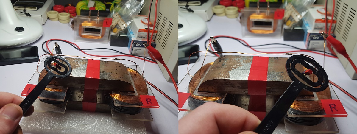
This is how ZPM is looking like:

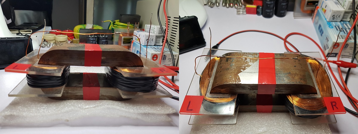
ZPM is using an Metglas AMCC-200 core, I bought two of them in 2017 for my research on Bearden's MEG; unfortunately I failed to make the device work even if I tried for two years; that's why I was silent here because I had no interesting results to present about my research.

I'm putting links about AMCC-200 technical specs here:

Hitachi - AMCC Cores Technical

Hitachi - AMCC Cores Presentation

I recommend checking how Metglas cores are produced and read about their special characteristics so you know what you're dealing with; remember Metglas was something produced in 70s for military and space technologies.

Let me clarify something here, it's possible that Metglas (which is yet kind of expensive) is not needed for reproducing this device, maybe it works very well by using ferrite cores and using much lower frequencies, I'm just describing what I'm using in my research now.

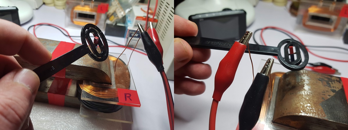
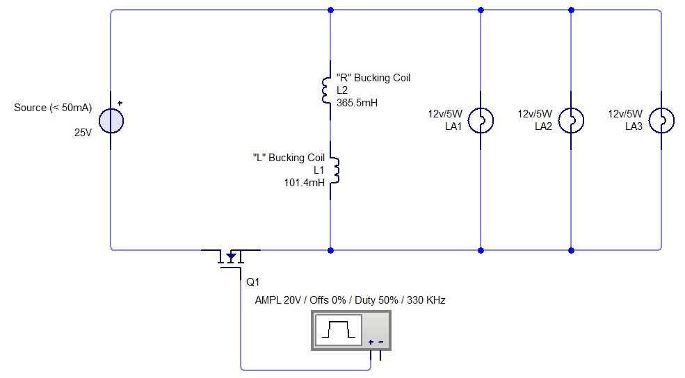
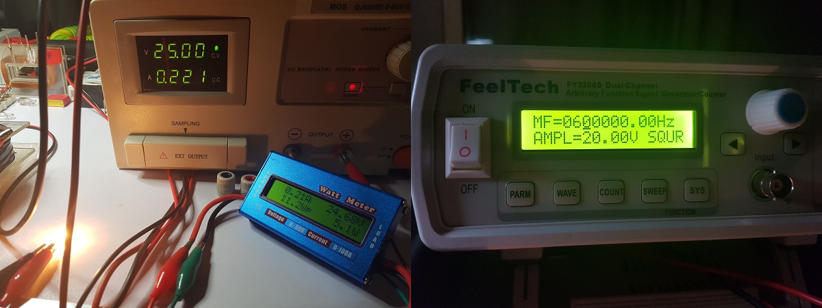
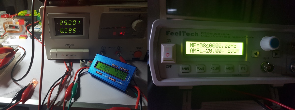
It has two bucking coils (marked the with "L" and "R") winded in a way that when they're connected in series and powered on, their magnetic fields are opposing.

L coil has 101.4mH inductance and approx. 150 turns made of 0.8mm standard copper wire for coils. These are the complete characteristics I measured with my LCR meter:

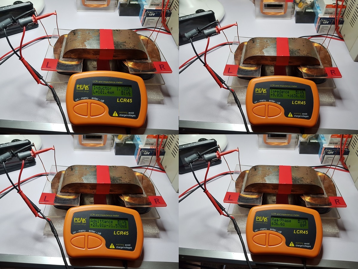
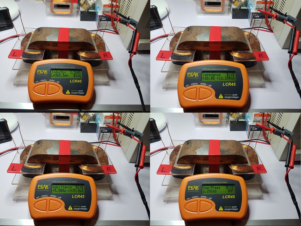
R coil has 365.5mH inductance and approx. 300 turns made of 0.8mm standard copper wire for coils. These are the complete characteristics I measured with my LCR meter:

My guess is it's not important the ratio of turns and inductances between the two coils, I'm presenting this data just so you know the characteristics of the device I'm working with. Probably different ratios will result just in moving the optimum frequency ranges upper or lower and also different voltage and current on output but I don't think that will have significant impact on device's over-unity capability.

"If you want to find the secrets of the universe, think in terms of energy, frequency and vibration."
Nikola Tesla

Attached Files

  • Liked by
  • Inception
Fighter posted this 19 June 2019

Before connecting the two coils in series I wanted to make sure the magnetic fields produced by the two coils are opposing so I powered each coil separately and checked the polarity of its magnetic field:

Then I connected the coils in series and checked again that their magnetic fields are opposing:

"If you want to find the secrets of the universe, think in terms of energy, frequency and vibration."
Nikola Tesla
  • Liked by
  • Inception
Fighter posted this 19 June 2019

And this the schema of how the device is used:

I know what you're thinking. "Wait, those light bulbs are powered by the source, not by the device ! šŸ™‚

Not entirely true... Initially when the circuit is powered on maybe for few milliseconds could be true but if the frequency is optimum then the light bulbs will take only few milliamperes from source, the rest of the power they require will actually be provided by ZPM. As I said what's new in ZPM is the way the bucking coils are used in order to provide power and (as the source is displaying) the voltage for the light bulbs is still provided by the source but almost all the power required by the light bulbs (for example two 12V/35W halogen light bulbs) is actually supplied by the ZPM while source is only providing only a few milliamperes.

As a note: there is a limitation of how many light bulbs you can add in the circuit; for every light bulb you add you will need to find another optimum frequency to make the power taken from the source to go down to few milliamperes again. Always the new optimum frequency will be lower and depending on how much power the new light bulb requires you may need to decrease the frequency with maybe 100-200 Khz. So adding too many light bulbs will force you to go under 100Khz range where the device will provide less and less power to the bulbs so they will start to get more and more power from the source.

"If you want to find the secrets of the universe, think in terms of energy, frequency and vibration."
Nikola Tesla
  • Liked by
  • Inception
Fighter posted this 19 June 2019

Here is the process I use to find a new optimum frequency when I change the number or type of lightbulbs on the output (in this example for a 12V/5W light bulb):

"If you want to find the secrets of the universe, think in terms of energy, frequency and vibration."
Nikola Tesla
  • Liked by
  • Inception
Fighter posted this 19 June 2019

Well, no more available time for now, I'll post more info when I'll find some time again...

"If you want to find the secrets of the universe, think in terms of energy, frequency and vibration."
Nikola Tesla
  • Liked by
  • Inception
Vidura posted this 19 June 2019

Hey Fighter, I will post here answering to your latest post In the delayed conduction thread. Regarding the feedback loop I am not agreed, not generally , there may be applicable cases like J. Bedinis Battery charging Devices, where he stated the feedback made them fail to work, but many others do use feedbacks:  Figurea, Kapanadze, Don Smith, Floyd Sweet, including any convencional Generator for the field winding. Your primary Dipole is the power source, it's dipole is destroyed and recovered continuously.

For my comments about the driver I am sorry that I have not been clear enough. It depends on the employed circuit of course, but basically i addressed to a  possible energy transfer from the signal generator into the circuit. A small capacitance like the gate of a MOSFET can transfer considerable amount of energy at high frequencies, specially if you use the S.G. directly to drive the MOSFET. A SG. can output perfectly a few watts of power, this can influence in your measurements, you would not see this on your input measurements, it can be avoided by using optical isolating drivers, or dedicated optocouplers to separate the signal source from your  tested device. If you need help for a circuit diagram just let me know, or you could use the design of the power switch modules posted in my thread about switching tool development. Regarding the scalar waves, there's nothing misterious about, It only means longitudinal waves, which are oscillating in the direction of the propagation, in contrast to transverse waves , they oscillating perpendicular to the direction of propagation. At high potential and frequency the longitudinal waves can damage many dielectric materials. A well known phenomenon when experiments with Tesla Coils are performed. Keep up your work and thanks for sharing. Vidura.

Vidura

  • Liked by
  • Inception
cd_sharp posted this 20 June 2019

Hey guys, Vidura

A small capacitance like the gate of a MOSFET can transfer considerable amount of energy at high frequencies, specially if you use the S.G. directly to drive the MOSFET.

Yes, but the S.G. should heat up, especially if it does not include any heat sink.

If you know how to build such a device and you're not sharing, you're a schmuck! - Graham Gunderson

  • Liked by
  • Inception
Fighter posted this 20 June 2019

Hi guys, I'm currently at work so I don't have too much time but I'll try to address some concerns.

About source's readings, I double-checked it using this wattmeter while powering up the device: 

https://www.optimusdigital.ro/en/others/2431-watt-metru-dc.html

By setting an non-optimal frequency I forced the ZPM to take 300mA and 221mA from source because at lower power consumption (like 85mA in the third image) the wattmeter will just display "0.00A", I suppose it was not made to measure a value so low in amperes.

Please keep in mind that the wattmetter itself is taking some current so the source's display will show slightly higher current values than the wattmeter. So about this I'm 99.99% percent sure source's readings are correct, don't think it's possible to have both source and wattmeter fooled and displaying milliamperes while the power drawn to be amperes.

Other thing that I tried to make sure the source's readings are correct: the source has an physical amperage limiter so you can set the maximum current it can provide before its auto-protection is triggered on. So I set the limiter to few milliamperes and tested with an 12V/5W bulb light, here is a video with the test:

About signal generator, I don't see it capable to provide amperes, based on my research these things can't provide more than about 100mA. Here is a video where this model is opened up:

Frankly I don't think it's possible to have two 12V/35W halogen light bulbs powered by that little transformer you see inside of the signal generator without it being destroyed already.

About the MOSFET driver, it's powered directly from source so it can't provide power itself.

"If you want to find the secrets of the universe, think in terms of energy, frequency and vibration."
Nikola Tesla
  • Liked by
  • Inception
Fighter posted this 20 June 2019

it can be avoided by using optical isolating drivers, or dedicated optocouplers to separate the signal source from your  tested device. If you need help for a circuit diagram just let me know, or you could use the design of the power switch modules posted in my thread about switching tool development.

As I said I'm a beginner about electronics so I will try to find out about optical isolating drivers and optocuplers. How would the simpler schematics for something like this would look like ? Would be helpful to know what components to look for, don't know if I'll have time now to build something like this but I can add it to my to-do list. Thanks !

"If you want to find the secrets of the universe, think in terms of energy, frequency and vibration."
Nikola Tesla
  • Liked by
  • Inception
Close