
I transferred my thread on Ferro-Magnetic Resonance here to BeyondUnity.org
YoElMiCrO's Ferro-Magnetic Resonance
- 10K Views
- Last Post 25 January 2026

Jagau
posted this
28 February 2020
Hi Vidura and YO
The second diagram of yo surprised me
we see very well the 4 states for a single oscillation
What surprised me as said will drain the coil is noisy but I must use a very high DTC not to consume ampere at the input. In study.
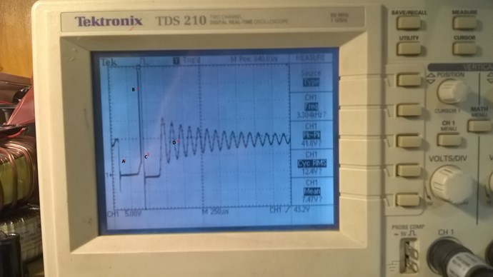
The bemf is so strong that the third quarter takes off a bit more and in the fourth the damped wave
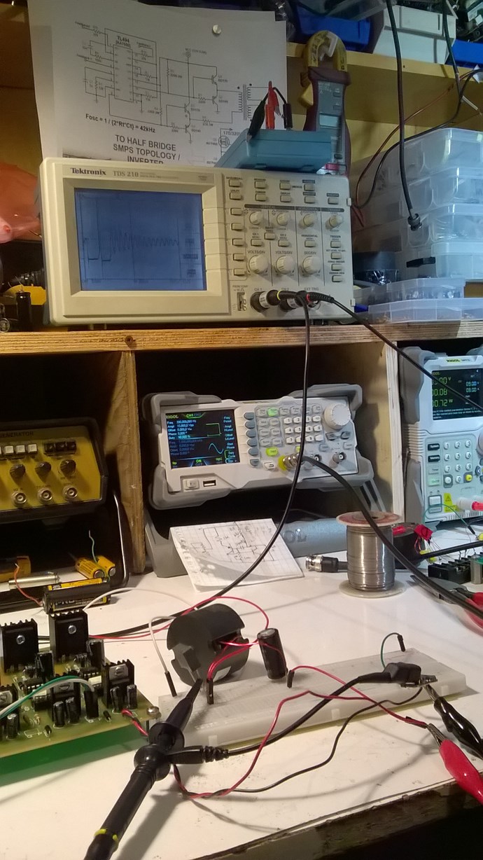
Did it with my new reliable switching card
Jagau
What we consider to be empty space is merely a manifestation of unawakened matter. N.T.
- Liked by
-

-


Vidura
posted this
28 February 2020
Friends,
If I may for a clearer understanding these images. this is the theory from Yoelmicro, what he explained to me:
below we see a nearly quadratic hysteresis loop :
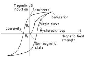
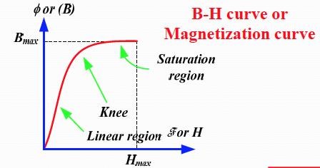
this means that the magnetic flux decreases very little from saturation to remanence. This is a requirement of the material to get the effect. in the following image we see the relative permeability for a given material, with it's negative slope between μmax and μsat.
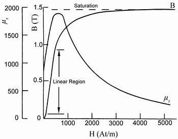
We have to aim to maintain the working point of the inductor-transformer in the negative slope. the steeper the falling curve the greater the amplification factor. This causes that when the applied field decreases, the permeability increases, just the other way around than in the linear region. this make the hysteresis loop circulate the other way around, it's like a time reversal, and thus can pump energy from the aether.
generally a current regulated switching is required for stable operation.
Vidura
Vidura
- Liked by
-

-
-
Jagau
posted this
28 February 2020
Hi vidura
I don't understand what Yo meant.
The permeability of a ferromagnetic material is like the ease (less resistance) to the penetration of the external magnetic field "H". So if the external field increases the ferromagnetic material becomes less permeable to the external field and the permeability curve decreases ( the core becomes less permeable and become more resistive) in negative way and this is normal, what we see in your graph.
I would have rather thought that it spoke about the remanence of the material ie the bridge between Br and Hc the coercive force?
please correct me if I make a mistake.
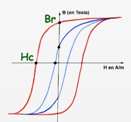
Between Br and Hc isa free force i think
Jagau
What we consider to be empty space is merely a manifestation of unawakened matter. N.T.
- Liked by
-
-
Vidura
posted this
28 February 2020
Jagau, If you look at the second graph you can see that the relative permeability in the linear region increase from mu init to mu max. This region is used in conventional EE. Then from mu max. to mu sat. There's the negative slope. When the external field continue increasing, the permeability falls. Now at or near saturation we switch off the external field and the flux in the core start decreasing, while the permeability is now increasing, just the opposite way as in the linear region. Then we let it decrease, but only until reaching mu max. Then we energize the input again, starting the next cycle. Due to the cuadratic hysteresis we have to apply only a small amount of input power to bring the core again into the saturation region, less than the energy which can be extracted during the work cycle. I hope this helps for clarifying. Vidura.
Vidura
- Liked by
-
-
-
Vidura
posted this
28 February 2020
Maybe I should add that we are using DC pulses, so the left half of the hysteresis loop will not apply, we will not change the sign of the magnetic field, so Hc will not be reached. the core remaining magnetised in the positive half cycle only.
Vidura
- Liked by
-
-
-

UndisclosedMember
posted this
28 February 2020
Hey Guys,
@YoElMiCrO - Is this your theory? Do we understand this correctly?
The BH Curve, or the Hysteresis Curve is typically an Alternating Current Concept, the Magnetic Field pushes through a full cycle. We know the Magnetic Field is Current I through N Turns, which is M.M.F. There are Losses just in the BH Curve without loading the Transformer.
Of course, if the BH Curve is Non-Linear. B is Flux in Gauss, and H is Strength, so this Graph is Density vs Strength:
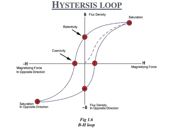
The Knee of the BH Curve, marked as b and e, is where we see the most Non-Linearity, but what is Non Linear? The Inductance of the Coil is lost at saturation, so this point is where the Coil is moving into Non Inductive and Inductive again. This is a material Effect, the Core itself is moving in and out of saturation at the knee, which is marked as b and e.
Some time ago, I published a document: What's it going to take to get OU? in that paper I gave some examples of this Inductance change and what it would mean achieving the Energy Gain. I looked at this from the point of Energy Stored in an inductor: 0.5 LI2
Looking back, I got my math wrong, squaring the Inductance, not the Current. However, a simple review:
- L = 2.
- I = 3.
We get: 0.5 x 2 x 32 = 9.
- L = 7.
- I = 3.
We get: 0.5 x 7 x 32 = 31.5.
The truth of the matter is, I does not stay constant, as L changes, I is forced to change also. So my math is not valid and does not take into account these changes. Of course, the definition of Inductance defines how Current travels through an Inductor. So more work is required in this area.
To make the Inductance change, then the Knee is where one should work:
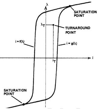
One Coil getting you up to the "Turnaround Point", where a normal transformer is at maximum Magnetising force, and the other Coil pushing up over the knee and back again. Of Course this down hill is where one may see an energy gain.
@YoElMiCrO - Is this your theory?
Just so we are clear, my work is different from this, although there must be an opposition, I believe from Core to Output Coil is the mechanism. Energy must come from a Source, it cant just appear from fresh air. So a Pumping of sorts must occur.
- Liked by
-
-
Vidura
posted this
29 February 2020
Hey Friends,
It is indeed a very interesting theory. I believe that there has arise some confusion regarding the BH loop. We will see If Yoelmicro can clarify. But if I understood correctly, the theory and the related energy gain is only related to the non linearity of PERMEABILITY. The BH loop, which is actually the AC response of a given core, was only mentioned to point toward a specific property of some core materials, which are required to make benefit of the effect. That is that the relationship between Bsat and Br should be close to 1. So lets see what Yoelmicro has to say, he is actually the transformer expert, which I think is of great benefit for the forum community .
Vidura
Vidura
- Liked by
-
-
-
YoElMiCrO
posted this
29 February 2020
Hi everyone.
I will try to explain what I understand is happening, I have to say that it is more complex
that this approach, but more than enough.
@ UndisclosedMember.
Yes, it is like that.
With regard to the hysteresis curve it is merely illustrative.
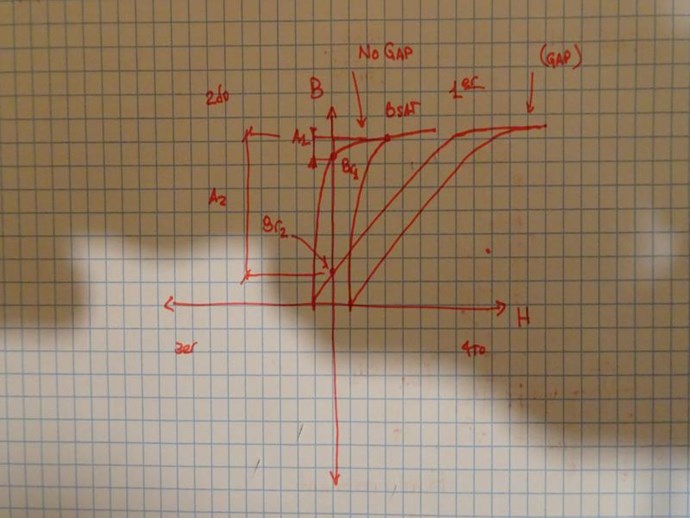
Going deeper into this we can define two areas within the first quadrant.
The area between Br / Bs is solely responsible for storage
of energy, that is why in the Flybak topologies a gap is necessary, because this
Increase the ratio Br / Bs.
And the area within the hysteresis loop, this represents the quality of said material,
It is directly related to the losses of this.
I think an image says more than words:
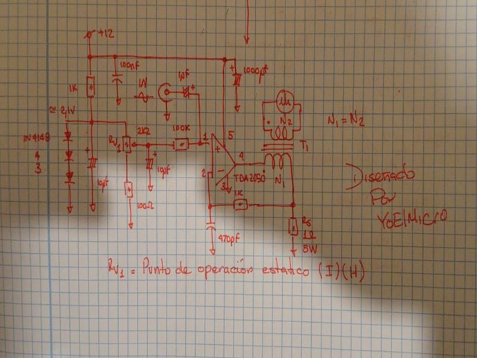
This is the first circuit I designed to study the phenomenon:
Looking at the material / core datasheet we take the value of H such that it is found
approximately 2Bsat from the first quadrant, after the core we get
the value of the effective magnetic length.
With these values and using the Biot-Sabart law we calculate the number of
turns for that H obtained.
It would be as follows ...
N = (H * le) / (0.4 * Pi * I)
Where:
H = Magnetizing force in oersted (Oe).
I = Current in amper
le = Effective magnetic length in centimeters
N = Number of turns.
The circuit current variation is approximately between 100mA and 2A,
margin more than safe for the TDA2050.
Ideally, apply on 1A and calculate the number of turns using the formula above.
Then we apply at the input a sine function with frequencies between
1Hz ~ 20KHz, we will start with a low amplitude, say 100mV while
We look for a maximum on your way out.
Once that maximum is found we can vary the input amplitude.
Not all materials work, the best are as previously commented
those that the Br / Bs ratio is close to the unit.
These can be of Amorphous, Nanocrystalline or any other type with said characteristic.
@Jagau
If we start thinking ...
Within a deep saturation Ur = Uo and as we know the inductance
related to the solenoid that forms the inductor decreases to the point that now
its value is equal to if it had no core, in this way we can say
that virtually the core is in a vacuum.
During the non-active cycle the core will return virtually again, only that it is
You see that entity will be responsible for your return.
I think it is permeability that is capable of acting as an intermediary in the process
and the inductor would be the collector
I currently believe that E / H are independent and natural entities,
however, as an action / reaction one evokes the other.
- Liked by
-
-
-
Jagau
posted this
01 March 2020
Hi yo
I'm starting to understand the purpose of this circuit to give us a certain measure of the core's hyteresis, but we will also have to find another circuit which will give us another equally significant value,
the permeability of the core, the 2 characteristics are so important.
Jagau
What we consider to be empty space is merely a manifestation of unawakened matter. N.T.
- Liked by
-
-
YoElMiCrO
posted this
02 March 2020
Hi everyone.
@Jagau.
If you look at the circuit it causes it to work only in the first quadrant.
The variable resistor sets the operating point so that the current is always positive.
I just wanted to see if Ur's negative behavior is real and compare it to the behavior of the Leo Esaki (Tunel) diode.
Looking at this image will be clearer.
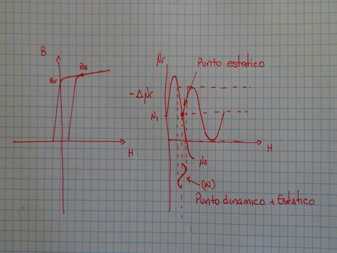
The relationship between Br/Bs also dictates the negative slope of a
given material The closer to the unit the greater the slope
and therefore greater amplification thereof.
Regarding the experiment you did, I can say the following.
If you look after turning off the Sw, the drain voltage of the mosfet rises sharply,
but the time that remains is extremely small.
That indicates that now the series inductance is very low and is discharged through
of that new time constant SQR(LC)=t, during this new semi cycle
the mosfet's parasitic diode enters conduction returning energy to the capacitor
of the source and the time that remains negative increases because now you will have to
leave the first quadrant to the third and saturate the nucleus in that quadrant.
And so while there is energy left in the capacitor.
Explain why so low current.
Good demonstration of nonlinearity in inductance.
Thank you.
YoElMiCrO.
- Liked by
-
-
-

Support Our Research Platform
Our Beyond-Unity Devices
Members Currently Online:
No one online at the moment
This Week's High Earners
-
-
-
-

-

-
-
-

-
Categories
