
I transferred my thread on Ferro-Magnetic Resonance here to BeyondUnity.org
YoElMiCrO's Ferro-Magnetic Resonance
- 10K Views
- Last Post 25 January 2026

Jagau
posted this
13 March 2020
Hi yo
Thanks for sharing the schematic.
After a very rough initial analysis of the circuit, you have a generator (PIC) which activates 2 mosfets via a mosfet driver.
2 different frequencies are produced on each side of the 2 coils.Maybe you want 2 frequencies to fight or push one after the other ???
Jagau
What we consider to be empty space is merely a manifestation of unawakened matter. N.T.
- Liked by
-

YoElMiCrO
posted this
23 March 2020
Hi everyone.
As I commented earlier, with the circuit I made I could
perform innumerable physical tests that were corroborating the hypotheses
varied that arose on the actual operation of the circuit with two TL494 from Akula.
After doing a lot of analysis this is the best approach.
I will try to explain its operation as simple as possible!
The circuit in question is that of the two TL494s, I think flashlight # 3.
It has a TL494 in free osc mode, frequency and duty cycle are controlled.
the duty controlled from pin 4 which controls the dead-time when configured
in push-pull mode, pin13 to Vref.
It is configured in common mode, since pin 13 at ground potential.
In this way we can control the duty 0 ~ 100%.
This free oscillator is key in its operation, but now we will see it.
The following TL494 is a Boost-Converter whose duty does not exceed 50%,
This is in charge of keeping its operation stable through the control loop,
which modifies the duty inversely proportional to the output voltage.
This is my point of view on the concept of operation.
This circuit involves two concepts, one that is already known and the other still under study.
The first one tries to have the least loss, (better efficiency) and it goes away that
reaching a maximum BH/2 magnetic energy is better to increase it cycle by cycle.
The second is about the negative region of ur.
It happens as follows ...
The free oscillator circuit causes increments of 100Gaus for example.
Your duty in question will be such that EdcTon = VfbToff and the stored energy
BH/2 will return to the input capacitor, this way the source will only have to
provide the energy of losses of the circuit and its consumption will be very low.
Now the Boost-Converter is participating.
It has a lower frequency such that its maximum duty (also controlled
from pin 4) fit the number of free oscillator pulses needed that
increase the energy discreetly until B is such that its ur is maximum.
As the two coils have the same phase, during the time that it is active
the primary with the highest number of turns (the Boost-Conveter), the one with the fewest turns will see a short
during the toff cycle and will not be able to release stored energy BH/2
because EdcTon is now unequal to VfbToff.
This causes the current to increase cycle by cycle, just as the Boost-Converter applies
Toff the short seen by the free oscillator is no longer, this causes all the
stored energy release, but remember that this oscillator is free.
During this Boost Toff time the tension in the free osc mosfet drain
it will be higher than Edc and its next cycles over saturate the core making it pass
by the negative slope of ur, in this way during the Toff time of this oscillator
free the flyback voltage peak (Vfb) in the drain will be of various magnitudes (So
protection in the mosfet drain) while the energy stored in the area lasts
left of the hysteresis (Br/Bs) until it is completely delivered to the
Input Load/Capacitor.
It is this energy that added to the stored BH/2 causes the AU.
Now we have an energy that comes from the ferrite itself + the one that we previously stored
cycle by cycle.
This explains the reason for a gap in the ferrite.
I will make a final circuit with discrete ICs and when it is 100% functional
I'll post it so all can replicate it.
I hope serve something.
Thank you in advance.
YoElMiCrO.
- Liked by
-

-
-

Jagau
posted this
24 March 2020
Hi yo
Very interesting, this is the major part of AU
It is this energy that added to the stored BH/2 causes the AU.
Now we have an energy that comes from the ferrite itself + the one that we previously stored
cycle by cycle
yes it serve and and I appreciate your point of view thank"s
Jagau
What we consider to be empty space is merely a manifestation of unawakened matter. N.T.
- Liked by
-
-
YoElMiCrO
posted this
25 March 2020
Hi everyone.
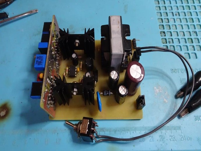
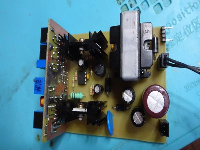
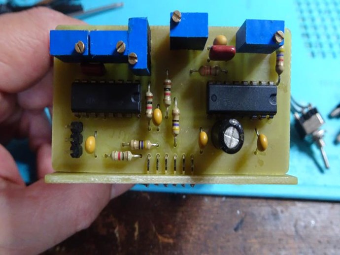
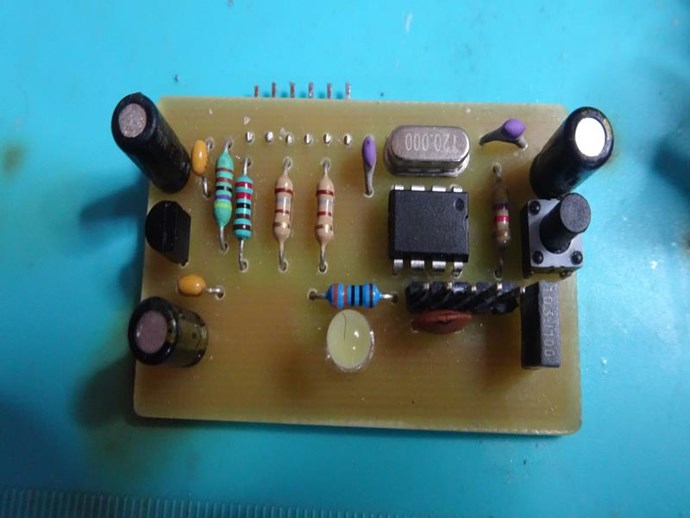
I have the final hardware ready.
Modify the control stage so that we can all replicate.
It is made with discrete components and I think easy to get.
The core is an EI33/3C90, the common ones in computer SMPS and TL494.
Later two 556 timers that I think are easier to get.
Here the images of the hardware.
Control with verifying the correct mode.
As I commented before, when it is 100% I publish it in this tread.
Thank you in advance.
YoElMiCrO.
- Liked by
-
-
-
Jagau
posted this
27 March 2020
Hi yo
When you talk about the circuit with 2 TL494 is that what you mean?
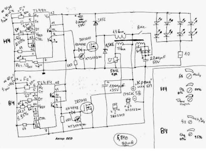
If we look at the parthened output coil, it polarizes the center with the positive and activates the 2 mosfets on the negative side with two frequencies in push pull mode, i think so it is the best solution.
Jagau
What we consider to be empty space is merely a manifestation of unawakened matter. N.T.
- Liked by
-
-

Vidura
posted this
28 March 2020
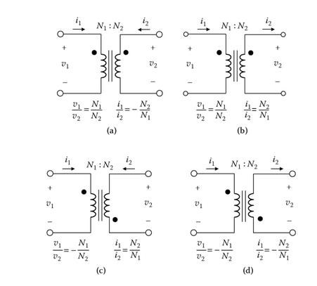
Hey Jagau, Thank's for posting the original schematic. The Two switches are working in the same direction, not push-pull. The dot notation shows this, and also according the theory of the negative slope of permeability the inductor is driven at the first quadrant of hysteresis, between Br and Bsat , there is no magnetic reversal, but two different frequencies. Regards Vidura.
Vidura
- Liked by
-
-
Vidura
posted this
28 March 2020
Hi Vidura
These new technologies are fascinating to study,
do you use the non-oriented silicon steels or the oriented steel ??probably the non-oriented ones which are more versatile
Jagau
Sorry I didn't see this post earlier, Yes it is non orientated silicon steel, the most common quality from stator of universal motor. I will do more testing with this cheap materials. Vidura.
Vidura
- Liked by
-
-

UndisclosedMember
posted this
28 March 2020
I support YoElMiCrO's work and Ideas! I think this can work, with enough work!
However, on the dot notation that Jagau and Vidura have bought up:
If one were to translate the Akula transcripts, he used the word: "generator" more than most other terms. The word: "transformer" was another very commonly used.
I urge, stay open minded. You just never know what your next discovery might be!
The very title here does serve as an example. A Voltage and Current is present. We human beings have very few methods of making this occur!
A Quote from Akula:
All schemes to develop and execute on principles of operation (Transgenerator magnetic field Andrey Melnichenko) and what to do with Pantyuhavu have!
I ask, try to stay open minded.
- Liked by
-
Jagau
posted this
28 March 2020
Hi vidura
I was not talking about the mosfet activation sequence I was talking about the two activation frequencies which operate the two mosfets in push pull mode and the pole totem mode does it very well. This frequency is probably not in phase and is different either a harmonic or another.
It is obvious and we can clearly see it in the diagram that the gate of the 2 mosfets are activated at the same time given that the 4 output transistors of the 2 TL494 oscillators are all connected together. The inventor of this circuit that I published succeeded in making it work as such and he will not tell us all its secrets.
If we look closely at the diagram there are delay components on one side of the mosfet drain. This circuit may seem simple to explain but it is a little more complicated than it seems
Jagau
What we consider to be empty space is merely a manifestation of unawakened matter. N.T.
- Liked by
-
-
YoElMiCrO
posted this
29 March 2020
Hi everyone.
@UndisclosedMember.
The circuit that Jagau exposes is the one I am referring to.
It is this circuit that I study to separate the events on which it is based.
So I think that as a schematic reference is fine.
I must say that it has errors, but as a reference it is fine.
@Zanzal.
I thank you for this topic here it is the real key to UA.
I already understood 100% what is happening, also other circuits
previously they claim AU works the same way.
As soon as possible I will write a document and send it to Vidura
for him to translate it from Spanish to English, nothing better than a human being.
Thank you Vidura for giving you.
YoElMiCrO.
- Liked by
-
-

Support Our Research Platform
Our Beyond-Unity Devices
Members Currently Online:
No one online at the moment
This Week's High Earners
-
-
-
-

-

-
-
-

-
Categories
