
I transferred my thread on Ferro-Magnetic Resonance here to BeyondUnity.org
YoElMiCrO's Ferro-Magnetic Resonance
- 10K Views
- Last Post 25 January 2026

Vidura
posted this
29 March 2020
Hello Friends, As it seems that the version of Yoelmicro's circuit which uses the PIC microcontroller is performing better, I thought to put this link of a low-cost pic programmer for those who want to replicate: https://www.microchip.com/Developmenttools/ProductDetails/PG164100 The regular price is 15$ , now until 31of march it is 50% off. Regards Vidura.
Vidura
- Liked by
-

-

-


UndisclosedMember
posted this
29 March 2020
@UndisclosedMember.
The circuit that Jagau exposes is the one I am referring to.
It is this circuit that I study to separate the events on which it is based.
So I think that as a schematic reference is fine.
I must say that it has errors, but as a reference it is fine.
Hey YoElMiCrO,
Ok no problem. Perhaps this post: Akula0083 30 Watt Self Running Generator and surrounding posts may be worth your review, I also researched this circuit some time back, redrawing it to try to further understand it, shared again here:
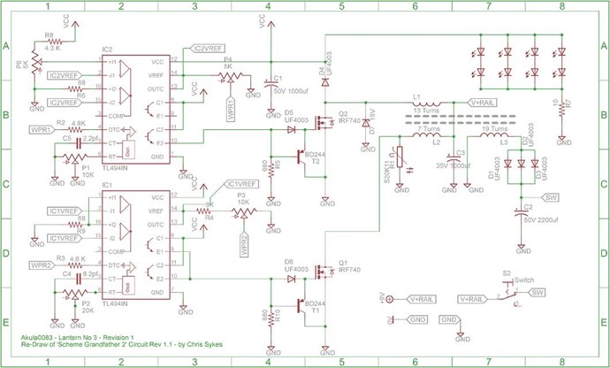
I also thought that circuit was very interesting. I do get the feeling you see things a little different from myself, the change in Magnetic Field as the Source of Voltage, so I will be interested in reviewing your method of "Generation" when you have more information on your theory.
Of course, always interested in others findings!
- Liked by
-
UndisclosedMember
posted this
30 March 2020
You know, after reviewing the video from A Valon:
I think I may understand more what YoElMiCrO is meaning!
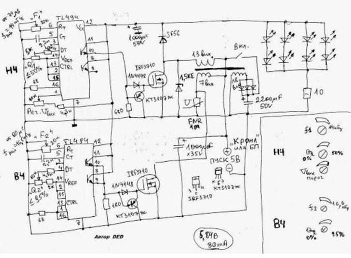
See the video Duty is set to: 25% and 50% respectively, same as the Grandfather Schematic. Two PWM's to two Mosfets same also! The Similarity's are too close!
We are dealing with two slightly different things here. Perhaps another way to get to the same end result. Still, lets see, Voltage and Current wise, lets see what YoElMiCrO finds as to these fundamental situations.
The voltage appears to be increased, by fundamental change in Inductance, which we know changes with the Magnetic Field, we know we need the Voltage up, this appears to be another way to do it, rather than delayed Conduction.
Lets see if the Currents via the Right Hand Grip Rule oppose during the "Generational" Phase?
Going back, reading, I owe an apology to Zanzal, sorry old friend! If I was not open enough to your new ideas. I should not have closed my mind to new ideas on getting the Voltage up, I am sorry!
- Liked by
-
UndisclosedMember
posted this
31 March 2020
Hey YoElMiCrO,
When you get a minute, I would really like to hear your answer:
Lets see if the Currents via the Right Hand Grip Rule oppose during the "Generational" Phase?
Using Conventional Current, Current flowing from Positive ( + ) to Negative ( - ), using the Right Hand Grip Rule, do the Currents Oppose during the "Generational" Phase between the two Coils?
It might be a little hard to document in small setups.
- Liked by
-
UndisclosedMember
posted this
31 March 2020
Going back, reading, I owe an apology to Zanzal, sorry old friend! If I was not open enough to your new ideas. I should not have closed my mind to new ideas on getting the Voltage up, I am sorry!
It is all good. That you recognize that there could be some small potential here means a lot. Thanks.
- Liked by
-
YoElMiCrO
posted this
03 April 2020
Hi everyone.
Do some experiments to see if they were really referenced
the same phenomenon when we use ferromagnetic core and when we don't.
The result was such that in both cases the same phenomenon is used.
In the case of the ferromagnetic core, it is already clear to me what happens when
enters deep saturation the same event occurs as when it is not!
The key to achieving is shown in this image, even though that was already known.
I think I only have to do a few experiments to finally
design a circuit that everyone can replicate.
Thank you in advance.
YoElMiCrO.
- Liked by
-
-
-
UndisclosedMember
posted this
04 April 2020
Hey YoElMiCrO,
Forgive me, I have a few silly questions!
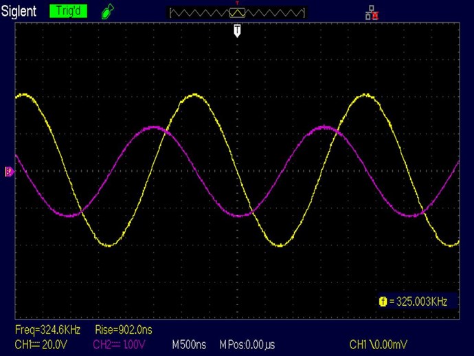
In your Scope Shot above, we have 90 degree phase shift, is this indicating LC Resonance? Or something else?
Of course we know resonance is required, was this the reason for your comment:
The key to achieving is shown in this image, even though that was already known.
Thanks for your post, I have read a few times and I am not sure on those points. Sorry to have to ask!
- Liked by
-
Vidura
posted this
04 April 2020
Hey UndisclosedMember, The shown scopetraces corresponding to input voltage and output voltage of a ferromagnetic core transformer, when the working point is in the negative region of relative permeability. The interaction with the environment causes the phase shift at resonance. Vidura.
Vidura
- Liked by
-
UndisclosedMember
posted this
04 April 2020
Thanks Vidura!
That is enlightening! Now I understand what YoElMiCrO was showing.
Of course for those that don't know, the CurrentInput to CurrentOutput should also be around 180 Degrees. At least normally!
Thinking about this more, of course, depending on the Circuit, the Input Voltage and Input Current phase angles will make a difference, if they are 90 degrees out of phase, a LC Resonant Circuit, then Input Current being the Catalyst for Output Voltage and that makes the 90 degrees normal. At least in my understanding and I ask you to correct me if I am wrong!
This is a case, if I understand YoElMiCrO's DUT, and I don't imply I do, just going on Scope Shots, then this is a case of The Change in Input Current creating the Output Voltage! Of course under resonant conditions.
Info at around: @ 26 : 10 and on through to the end.
Some may find the above video helpful?
I will be very interested in seeing future results!
- Liked by
-
YoElMiCrO
posted this
05 April 2020
Hi everyone.
@UndisclosedMember.
Yes, are the input/output voltages of the transformer under tests such
as Vidura says.
I already have the new control card designed, it should be able to
keep the phenomenon stable, so that we can extract energy.
This is the physically performed circuit.
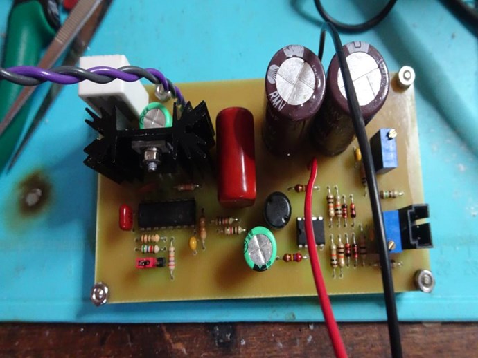
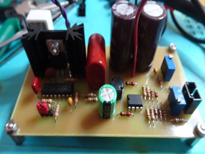
After testing that it works I post the circuit and the data of the energy collector.
Thank you in advance.
YoElMiCrO.
- Liked by
-
-
-

Support Our Research Platform
Our Beyond-Unity Devices
Members Currently Online:
No one online at the moment
This Week's High Earners
-
-
-
-

-

-
-
-

-
Categories
