
I transferred my thread on Ferro-Magnetic Resonance here to BeyondUnity.org
YoElMiCrO's Ferro-Magnetic Resonance
- 10K Views
- Last Post 25 January 2026
YoElMiCrO
posted this
06 April 2020
Hi everyone.
@UndisclosedMember.
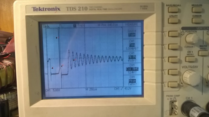
I apologize for just posting the waveforms without at least
say what it is about, I think with this image you will be able to understand better
what it is really referring to.
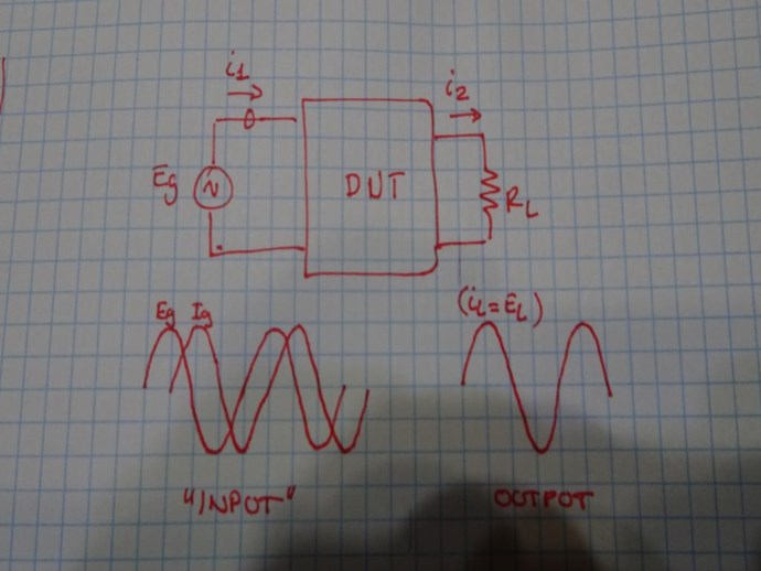
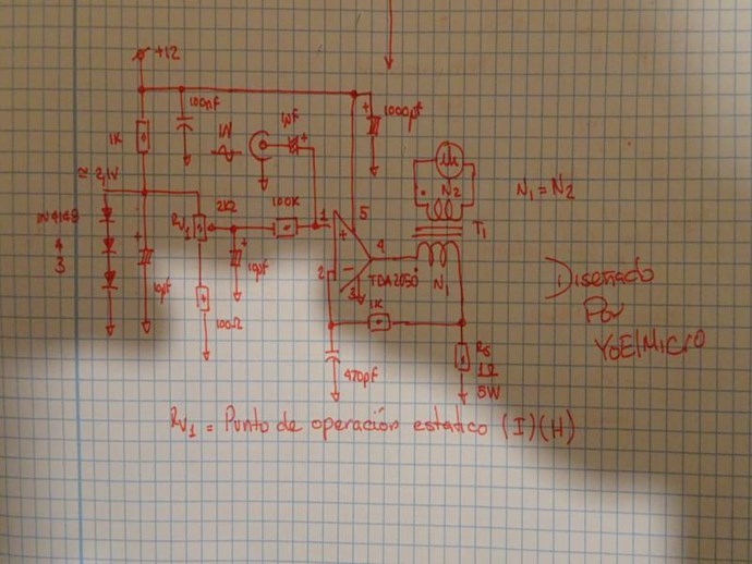
I must say that the DUT is just a common transformer, only that
It is made in an unconventional way and can be air core.
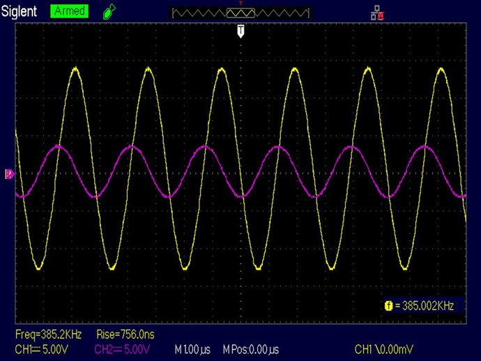
The phase difference seen by the generator source is 90 degrees
between voltage/current, while the phase difference at its output is 0.
In this way it produces useful work in its output while we spend
of the generator only the intersected E/I area and the latter
polarizes the medium in such a way that it increases the field E, being
their ratio of turns 1:1.
Something that for my knowledge should not happen under any circumstances.
But to understand something you need patience, a lot of it!
As you say, it is a resonance situation that does not obey conventional TM.
Still under study.
Thank you in advance.
YoElMiCrO.
- Liked by
-

-

-


UndisclosedMember
posted this
06 April 2020
I agree, on the Output, under Resistive Load Conditions, the Voltage and Current can be almost purely in phase. Real power.
Thank You for sharing your work YoElMiCrO! I see much clearer now thank you for the explanation.
- Liked by
-
YoElMiCrO
posted this
16 April 2020
Hello.
I've been a little busy with work.
But I have been able to carry out several experiments that corroborate AU.
In the shortest possible time I publish what I found, as well as
the circuit to replicate.
Sorry for the delay.
Thank you in advance.
YoElMiCrO.
- Liked by
-
-
-
YoElMiCrO
posted this
09 May 2020
Hello everyone.
This seems to be the end of the experiments.
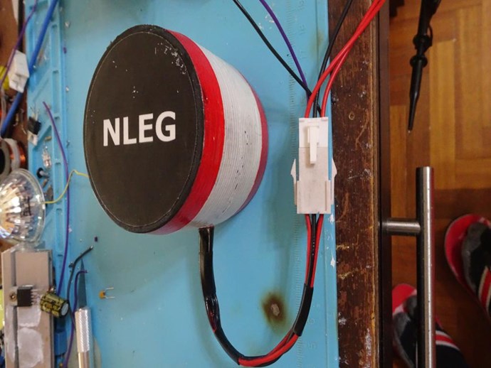
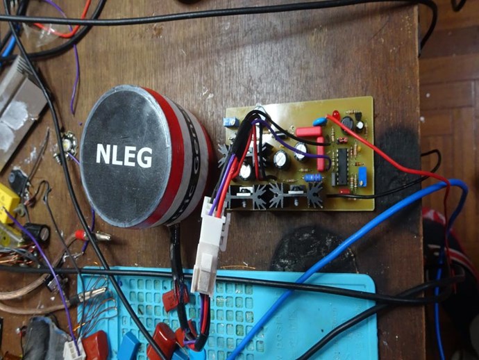
Here is a photo of the collector that I made in 3D.
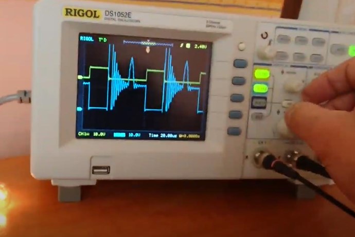
Some capture of the scope, in yellow the primary voltage
in mallow secondary voltaje.
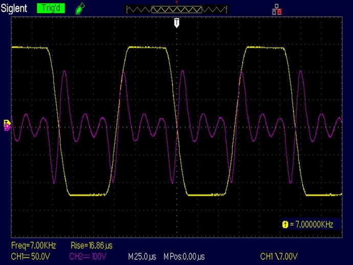
The control circuit is not yet finished, the tests are carried out with the
the last photos of this post which has a PLL and two digitizer,
I call it Non-Lineal Electric Generator (NLEG).
The final idea is to close the loop and take energy from the rest.
I will keep you informed.
YoElMiCrO.
Thank you in advance.
- Liked by
-
-
-

Fighter
posted this
09 May 2020
Did you made a estimation of the COP ? Because closing the loop involves energy loses (heat during the high-frequency AC to DC conversion process).
| "If you want to find the secrets of the universe, think in terms of energy, frequency and vibration." | ||
| Nikola Tesla | ||
- Liked by
-
-
YoElMiCrO
posted this
14 May 2020
Hello everyone.
@Fighter.
Yes, more or less calculate the losses associated with each circuit.
I still do not succeed, but it is a matter of analysis / solutions.
The circuit I test with contains a PLL,
power circuit, these consume about 30mA @ 12Vdc and
It has a buck converter with an efficiency between 75/85%.
This type of electricity is rare, I have to do more tests.
The PLL is a CD4046 operating with phase difference 0.
The pulse amplifier is a 30A peak IXDI630MCI power driver,
the buck converter an AP1501 and a double power diode MOSPEC F12C20C.
I have not had time to continue with it, but this end I resume.
I will let you know how the idea evolves.
Thank you in advance.
YoElMiCrO.
- Liked by
-
-
YoElMiCrO
posted this
14 May 2020
Hello everyone.
@UndisclosedMember
Note the similarity of the experiments.
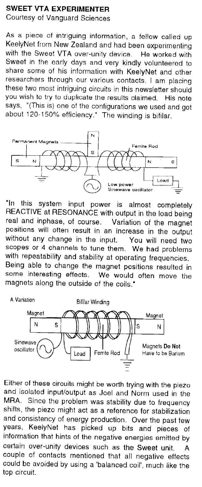
In the case of Floyd Sweet the magnets set the static operating point
while the inductor modulates the variation with a small current
of magnetic permeability.
In my case the static point is defined by the current flowing through the
same inductor while the alternating signal applied to the input modulates
said current.
It was this test that proved to Floyd Sweet that the nature of matter
It is different from how we imagine it, from that experiment it came directly
how to perform your SQM.
Thank you in advance.
YoElMiCrO.
- Liked by
-
-
UndisclosedMember
posted this
14 May 2020
Hi YoElMiCrO,
I agree, I viewed this image for a long time, not realising its importance, then my experiment came full circle and I ended up proving the importance in this diagram!
It is super Important, and for many they may not see how important, the best way I found to explain it is in the form of Energy "Generation".
At Resonance, what one Wire Carry's, the other Wire must also Carry, but the opposite way! Then that's a 2 for one scenario. Above Unity results.
Thank You for sharing YoElMiCrO! I appreciate your work!
- Liked by
-

Atti
posted this
22 June 2020
Hi.
I don’t know where the original idea came from. But it doesn't matter. I came across this idea years ago. There is a slight difference in this because in this drawing it is filled with a diode instead of a capacitor coupling.It connects not to the negative but to the positive branch.
And so the YoELMiCrO may be somewhat different
his work. Then the theory was not attached to the experiment. I only got to know ferroresonance at that time, so I didn't even have to look for anything. (I'm not aware of everything at the moment) I will combine the ideas in these drawings with Chris’s asymmetric transformer arrangement. (just have time for the tasks at last)
So the point is based on understanding the theory. Thanks for the description and comments everyone.
Atti.
- Liked by
-
Atti
posted this
22 June 2020
I definitely need to repeat this arrangement.
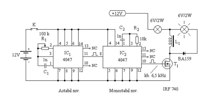
Implementation of Jagau:
Similarity:
- Liked by
-
-
-

Support Our Research Platform
Our Beyond-Unity Devices
Members Currently Online:
No one online at the moment
This Week's High Earners
-
-
-
-

-

-
-
-

-
Categories
