Fighter's ZPM (Zero Point Module) failed replication by Itsu

  • 8.1K Views
  • Last Post 18 December 2022
Itsu posted this 07 November 2022

Hello all,

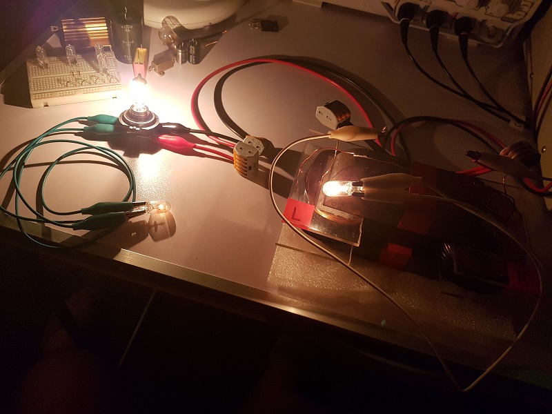
i opened this thread to discuss my replication of Fighter's ZPE (Zero Point Module).

I already opened a similar thread on OUR.com (https://www.overunityresearch.com/index.php?topic=4374.msg101654#msg101654 ), but will transfer some data from there to here.

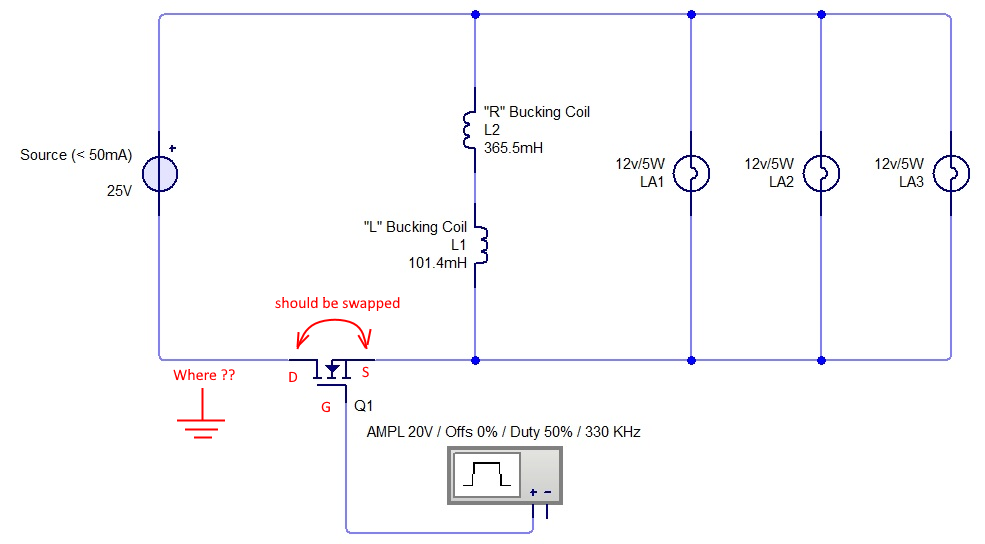
Initially i understood that the below diagram was correct and complete, but it turns out its not.
There is a ground connection somewhere, but i am not sure where it is exactly, hopefully someone can tell me.
The MOSFET is shown wrong as the Drain and Source should be swapped, which was corrected later in Fighter his thread so therefor the mentioning in red.

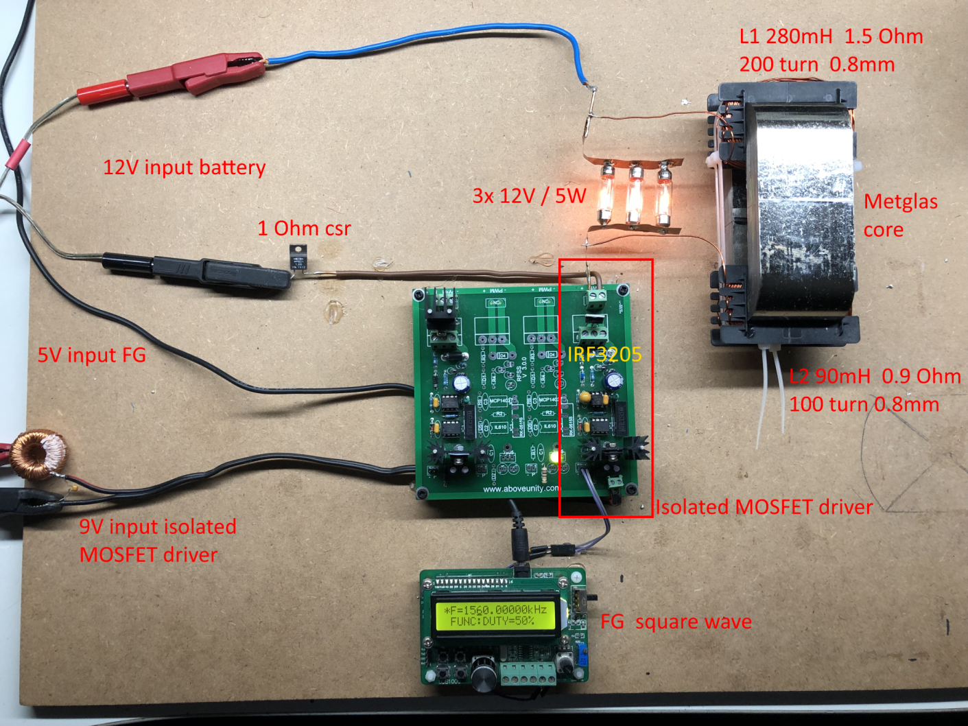
I have build up a similar circuit and the data is shown here: 
(Be aware that the induction measurement was done at 10kHz, but due to the influence of the metglas core it can be (and is) completly different on other frequencies, see my thread on OUR.com for a VNA scan of the coil/core)


I am using a 12V battery for now as my PS (minus NOT grounded) was acting weird due to all the pulses coming back from the ZPE device.
Up till now no special effects or resonance in a 0 to 5MHz range are seen with this setup, but as said the grounding may be the problem here.

Itsu
Fighter posted this 13 December 2022

Quoting:Vidura

This makes sense regarding measurement techniques, and as it is a switch mode PS it can be powered with DC on the input, so it would be a reliable data if rectified and filtered before the PS. Of course the unloaded consumption coud be substracted also๐Ÿ˜‰.

Sorry Vidura but I don't agree. It means overcomplicating thing and introducing errors, big ones.

DC source's own consumption is variable in time depending on DUT's behavior. Cannot be calculated so we know its own consumption so we can substract it from the COP calculation.

Also the energy dissipated by the switching circuit is variable depending on paramaters. I could run cold at certain frequencies or it can get very hot at other frequencies. That cannot be calculated so we can substract it from the COP calculation.

Why overcomplicate things and introduce big errors when we can just calculate the energy directly on DUT's input, those square pulses ? We have Jagau's formula for that. We will have 0 errors because there will be nothing variable in the COP calculation.

See my previous post example with the inefficient switching circuit dissipating many watts as heat. Those watts certainly are not consumed by the DUT. The same about DC source's own consumption, that is certainly not consumed by the DUT.

Regards,

Fighter

"If you want to find the secrets of the universe, think in terms of energy, frequency and vibration."
Nikola Tesla
  • Liked by
  • Vidura
  • Inception
Itsu posted this 13 December 2022

Quoting:bigmotherwhale

I dont want to upset you Itsu im trying to help but when you say you have the same as jagau im not seeing it. 

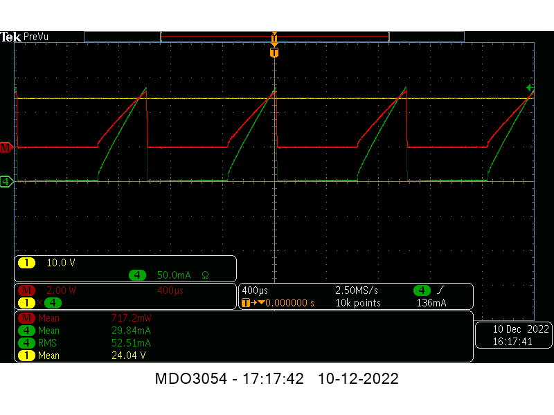
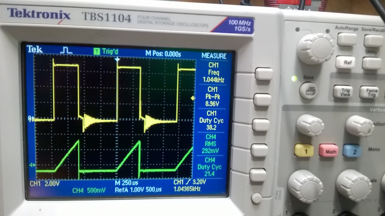
These are the two images i saw, one shows a flat sawtoooth with a very sharp transient shown by the shap peak on the end of the switch and the other is curved with no transient or ring down after the switch. Why is this? am i not looking at the right pictures here. 

There is clearly an effect here. 


BMW,

i am not easily upset, i am doing this kind of stuff since 2010, so i have seen all and more you can imagine coming by since then.

OK, we are looking at the right screenshots, and especially the green traces.

We see the same triangle shaped forms (i hope for you), but indeed there are differences as is with all different devices, none is exactly the same.

I do not know the values of Jagau his coils or any other detail of his circuit (does anyone else?), but i use the same voltage (24V) and the same load (bulb 120V / 4W).

But my bulb is only dimly on (536mW) while Jagau shows his is full on (4W), so there is a difference there probably due to the coils.

His input current is obviously stronger (292mA rms) then mine (52mA rms) and i can imagine there will be stronger transients and a sharper triangle shape.

But the basic form is there, the triangle shape IMO.

Itsu.

  • Liked by
  • Vidura
  • Inception
Itsu posted this 13 December 2022

Quoting:Vidura

Quoting:Itsu

Quoting:We need the whole circuit being powered especially here where it seems that the PS itself is an active part of the device, in fact, i think we might need to start measuring the input power from even before the PS if that is even possible in a practical way.


This makes sense regarding measurement techniques, and as it is a switch mode PS it can be powered with DC on the input, so it would be a reliable data if rectified and filtered before the PS. Of course the unloaded consumption coud be substracted also๐Ÿ˜‰.

Hi Vidura,

yes, that sounds like a plan, i can use a 200V DC PS to feed the switch mode PS and monitor that using simple DMM's.

I did that earlier on the Daly (nano pulser) replication and worked great and reliable.

Regards Itsu


  • Liked by
  • Vidura
  • Inception
Fighter posted this 13 December 2022

Quoting:Itsu

Quoting:Vidura

Quoting:Itsu

Quoting:We need the whole circuit being powered especially here where it seems that the PS itself is an active part of the device, in fact, i think we might need to start measuring the input power from even before the PS if that is even possible in a practical way.


This makes sense regarding measurement techniques, and as it is a switch mode PS it can be powered with DC on the input, so it would be a reliable data if rectified and filtered before the PS. Of course the unloaded consumption coud be substracted also๐Ÿ˜‰.

Hi Vidura,

yes, that sounds like a plan, i can use a 200V DC PS to feed the switch mode PS and monitor that using simple DMM's.

I did that earlier on the Daly (nano pulser) replication and worked great and reliable.

Regards Itsu


Okay then, you ignore what I say I'll ignore everything you do here.

You ignore the input calculation method also.

This is my last post in this thread.

Bye

Fighter

"If you want to find the secrets of the universe, think in terms of energy, frequency and vibration."
Nikola Tesla
  • Liked by
  • Inception
Itsu posted this 13 December 2022


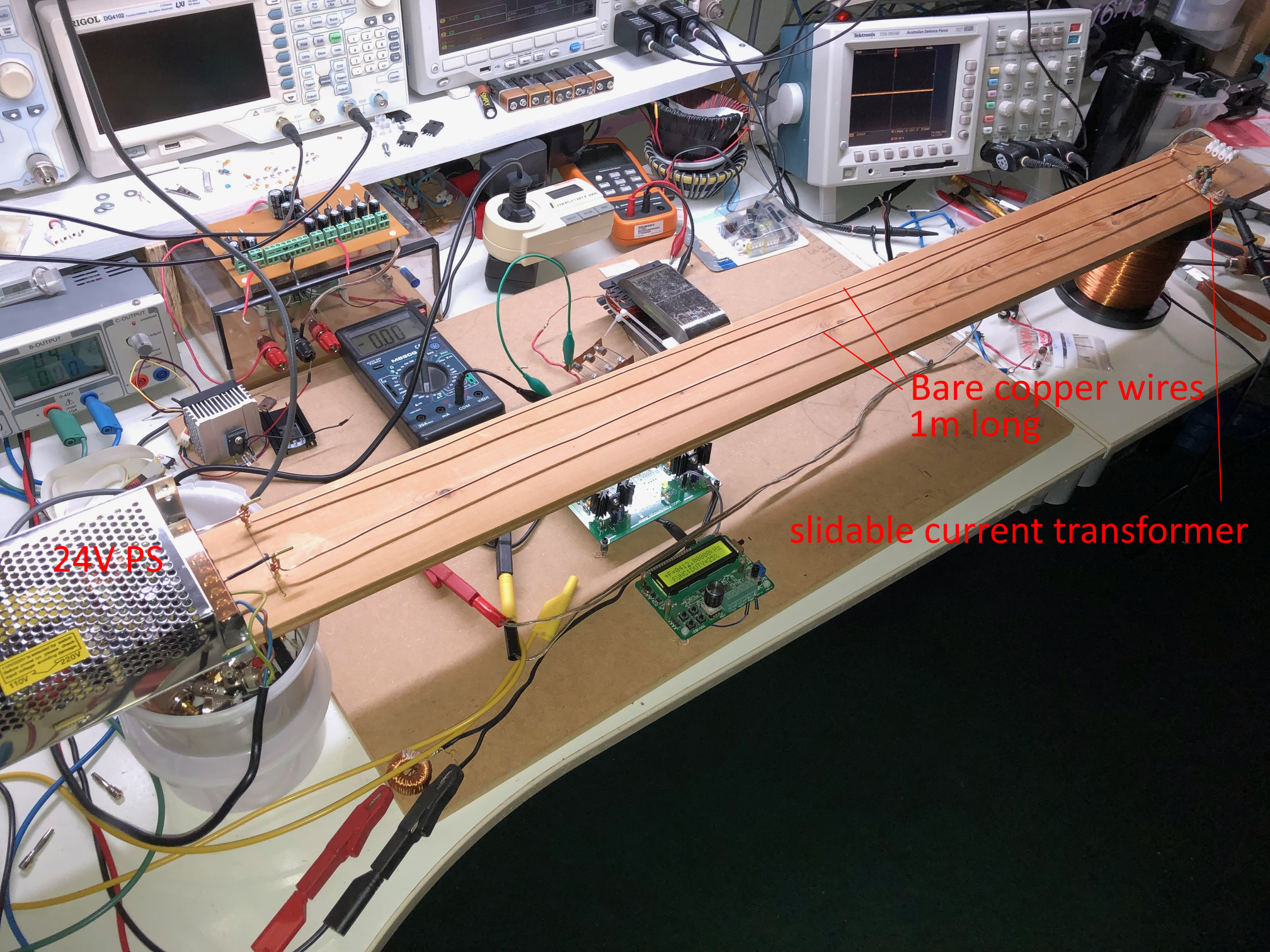
I put together this contraption:


It has a 1m long stretch of dual bare copper wires directly attached to the 24V switch mode PS on one side and a connection point to the normal device input wire leads on the other side.

There is a current transformer on the minus lead which is slidable across the length of wire.

This way i can make some rough current measurements and with the DMM / scope probe i can make voltage measurements across this length.

Some initial testing shows we have a steady triangle pulsed current across the 1m length, so no indication of a standing wave.

I did find that the voltage across the 1m does fluctuate from 24V DC (some rippling on it) at the PS side to 34V on the opposite side, especiall above 400kHz or so.

This raised voltage only occurs from about 3/4th from the PS side, and only then when the Fluke 179 DMM is put on top of the PS.

This 34V on 3/4th of the length will increase with used frequency of the device, but when picking up the Fluke DMM the voltage starts to fluctuate and go back to normal (24V) when hovering above the 3/4th part of the length.


So, it seems there is no standing wave, but the increased voltage seen on the fluke is caused by the high frequency noise disturbing the Fluke (specified for 20kHz or so) and setting it off.

Using a scope probe to do the same measurement across the 1m length confirms no standing waves and shows a steady voltage across the length of wire.

I will do some testing today and shoot a video.

Additional measurement suggestions are welcome.

Thanks,  itsu 


  • Liked by
  • Inception
Itsu posted this 13 December 2022

Fighter,

i personally told you that our discussion on input measurement is leading to nowhere and to forget about it.

But you still are coming back to it.

You desperately are trying to convince me of your views, which are noted, but i happen to not agree with them, get over it.

I won't let anyone force me into a specific direction or view unless i personally see in my experiments that it is correct.

I showed you that when using Jagau his formula i get the COP > 1 also, but i also showed that my input measurements via 2 different methods show the opposite COP < 1 and i believe that when an abnormal effect is noted (COP > 1) one should try to use as much different methods to confirm that abnormal behavior.

Itsu   

  • Liked by
  • Inception
Fighter posted this 13 December 2022

And you had other 3-4 members telling you that your measurement is wrong and they explained to you why. But you still continue with that.

And you don't get it. Your measurements means nothing as long as you don't have the input decreasing effect !

More than that instead of measuring exactly the input on DUT you try to add as consumption the energy used by your DC source and also the energy wasted in heat by your switching circuitry.What about the energy consumed by your neighbours applicances ? Consider that as consumed by ZPM too because they're on the same circuit with ZPM ๐Ÿ˜€

ALL THESE ARE NOT CONSUMED BY THE DUT !

Now you try to say there are no standing waves on the output of ZPM.

First of all you don't have a successful ZPM replica running.

Maybe your device don't have standing waves on output, here are standing waves on the ZPM's output:

And there is no "high frequency noise disturbing the Fluke", as you can see there is no Fluke in this photo.

Actually you're the one trying desperatly to "demonstrate" that ZPM doesn't work.

So you built, I don't know, something which doesn't work as ZPM and you're measuring that something pretending it's an ZPM.

So it really doesn't matter what you measure or how, at the end of the day me, Atti and Jagau have functional ZPMs while you desperately try to show they don't exist with your unsuccessful replication.

I never saw something so unprofessional in a replication in my entire life. And it's clear you fail on purpose because you do exactly the opposite of what should be done.

No wonder you and your buddies at overunity never came with something new in 15 years, you could have there even one of Don Smith's devices and you wouldn't be able to get out of your pre-established "measurement errors" conclusion... ๐Ÿ˜„

What you do here is just disinformation on purpose, just a joke pretended to be a replication.

And don't tell me to get over it, okay ?! Watch your words !

Actually, you know what ? Prepare your bags, you'll go back to your buddies within 24 hours. We have no obligation to keep this crap you produce on our site. It's time to end this bad joke.

"And now, after I failed my ZPM replication, let's measure its COP !"... Are you kidding me ?!...

Goodbye,

Fighter

"If you want to find the secrets of the universe, think in terms of energy, frequency and vibration."
Nikola Tesla
bigmotherwhale posted this 14 December 2022

 At the start of the replication there were signs that you were begining to get the effect to appear on the scope shots and you have literally "filtered" that result out.

 We see the same triangle shaped forms (i hope for you), but indeed there are differences as is with all different devices, none is exactly the same.

These are not the same waveforms, its plain to see, look at the thickness and striagtness of the slope and the lack of the tell tale inductive kick. 

But the basic form is there, the triangle shape IMO.

One is a curve and the other is not, the effect is not pronouced enough. 

Your coils are not opposing each other strongly enough, there is either not enough induction, input voltage, or the output (which also includes the input in this circuit) impeadance is too high. It really is that simple, change your circuit and see the effects change, no ammount of winding coils will solve the fundemental and simple problems you have.

You say the output power is lower than it should be, then turn up the voltage. 

Munny posted this 14 December 2022

Itsu,

I like the test rails you made, but I'm afraid until you get a waveform similar to Fighter's

Signature ZPM

It really isn't going to tell you much, which apparently it didn't.

Are you absolutely certain the two U-cores are opposing?  I mean, if you have them loose and apply a quick current, do they try to jump apart?

There has to be something so simple, you took for granted it's correct and didn't check it.  It happens, I've done it many times myself.  Usually I burn up stuff when it happens, but sometimes I spend days in the weeds only to find out I didn't solder a connection on like I thought I did.  Seriously, take your whole device and pretend someone shipped it to you  blind and you know nothing about it.  Start with that and just see if you missed something.

Anything I can do to help, just holler.


Vidura posted this 14 December 2022

Replying To: Itsu

Itsu, although I appreciate your efforts and methods. In order to not cause unnecessary conflicts and to stay unbiased, it has to be noted that the effect of decreased input while the load is powered, and the typical waveform is not yet present. Thus also the measurements are not relevant at this time still. Once the mentioned effects are achieved, I agree with as many tests as possible, to discard any mistake. Best wishes.

Vidura

Close