Romanian ZPM (Zero Point Module)

  • Topic Is Locked
  • 3.4K Views
  • Last Post 12 February 2023
  • Topic Is Solved
Fighter posted this 07 February 2023

This is the imported thread (from the old aboveunity site) about my ZPM:

For references I will keep the original posting date for every imported post.

Note: This thread is public, everyone can see it, even the visitors which are not members here.

For the posts made by former aboveunity members which are not members on our site I'll use a member placeholder named UndisclosedMember.

Regards,

Fighter

"If you want to find the secrets of the universe, think in terms of energy, frequency and vibration."
Nikola Tesla
  • Liked by
  • Jagau
  • Inception
UndisclosedMember posted this 06 August 2019

Hey Guys,

I am in firm belief Fighter has a machine that is well worth further experimentation!

When one has the Circuit tuned right, amazing things were seen, low frequency experiments were noisy and one could tell there was a lot of Magnetic Field Opposition.

If people want to learn, these very simple experiments can yield a lot of information! Simple and Cheap! Only taking a few hours to really get a good bite!

No one realised Akula was doing the same thing. A narrow, 0.5% duty Cycle pulse in some cases were enough to find the resonant point.

  • Liked by
  • Inception
UndisclosedMember posted this 06 August 2019

Hey Guys,

Fundamental Fact:

  1. Voltage is a direct result of the Change of the Magnetic Fields! 
  2. Current comes from the equal and opposite Force of Magnetic Fields!
  3. Two fundamental different things!
     

Lets be smart about this! Two Coils, we drive one, what do we want to occur, a pumping of Current well beyond our Input Stage. 

The Coils must Buck, its an evident fact and all here should know this already. Others, visitors, are still in an educational stage.

At a Coil Resonance, we can put a small, efficient pulse in, and get a big pulse out. The machines tagged as: ABOVEUNITY are examples of this. When we get a good output measurement on Fighters DUT then we can add this Tag.

Jagau is correct:

I noticed strange effects and I realized that the impedance of the load made a big difference in performance.
I am trying to check different scenarios.

Of course this is correct!

The Magnetic Fields are only going to pump properly if they are loaded sufficiently!

Remember: The Magnetic Field is Current flowing in a Wire. No Current, No Magnetic Field!

I wish others would get onboard and replicate these simple machines!

  • Liked by
  • Inception
Vidura posted this 07 August 2019

Hey Fighter and all, The effect that the light bulbs on different connected points (or different wire length) have unequal luminosity is a sign for standing waves at high frequencies. Comparable with Tesla's experience when he shorted a transmission line at one point with a thick copper bar and had at another point of the line light bulbs lit.

Vidura

  • Liked by
  • Inception
Atti posted this 07 August 2019

Hey Fighter.


That's why I call this an anomaly because all those light-bulbs being powered from the same wires they should share the output power equally so both 12V/5W light-bulbs should have equal luminosity. But as you can see it's not working like this, the device seems to have some kind of preference in how it's providing its output power.

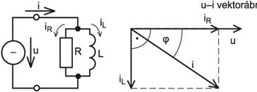
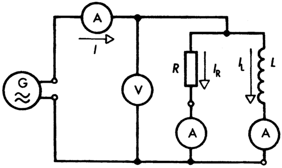
In my opinion, this is a parallel R-L resonance. Changing the bulb value also changes the cut-off frequency.
In the case of parallel switching, the voltage is the sum of the two circuits.
As a result, iR in phase with the resistor is formed, and iL is 90 ° late in inductance.

The impedance and phase angle of the parallel circuit are frequency dependent.
It would be nice to have an oscilloscope diagram where the two values are visible at the same time (current and voltage).
This would allow us to infer what is actually happening.
The figure only shows one roll, but in reality you have two rolls.

  • Liked by
  • Inception
UndisclosedMember posted this 07 August 2019

Atti,

I think you might be surprised when replicating this.

I don't entirely agree, your post is not aligned with what's going on in these devices.

Resonance yes, phase shift no.

  • Liked by
  • Inception
Atti posted this 07 August 2019

UndisclosedMember.

Probably. Nevertheless, a trial measurement would be worth it. Unfortunately, I don't have a Metglas core.

  • Liked by
  • Inception
UndisclosedMember posted this 07 August 2019

Hey Atti,

Yes I too always like to see a scope shot or two.

My work in this area show V and I to be less than 1-5 degrees.

I hope this helps!

  • Liked by
  • Inception
UndisclosedMember posted this 11 August 2019

Ive been watching, tonight, a bunch of video;s external too HYIQ members. , some good results everywhere. -

My best results thus far came tonight,  - series bucking coils on ferrite core. with parallel  PSU and globes...   COP2 , with sine waves and square waves. - but i im trying too work out if i can stick in a diode, like meyers circuit, and get more gains....  he was using ferrite. but also a series inductor..... -- i really want too fast track my learning untill my metglas arrives next week.

  • Liked by
  • Inception
YoElMiCrO posted this 16 August 2019

Hello everyone.

I think I know how it is possible to extract energy from the vacuum.
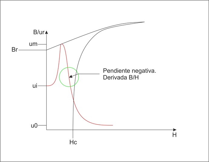
It turns out that the magnetic permeability behavior
It has a region in which it is negative!
As if it were a tunnel diode, it also has it.
Only in this, we draw the current from the source and its
behavior as an amplifier is real.
Because the negative region in ferromagnetic materials
It is expressed by permeability, it interacts with the vacuum.
Here the graph of their behavior.

This image is just a sample of how permeability changes
depending on the current through the inductor that makes up the system,
It is merely illustrative.
That is why there are two operating points, one is static and depends on the
load, and other dynamic and depends on the frequency.
I continue with the experiments that prove that the OU is possible, it is still a
Hypothesis not a theory.
It would not violate any thermodynamic law because it extracts the energy of an entity
We still don't understand.

@Fighter.
I still do tests to understand your experiment, but everything has to do
with magnetic permeability and standing waves.
The turns ratios must be quadratic because the inductance is.
This means that the turns ratios will be the root of 0.75, 0.5 or 0.25 of lambda for
one of your inductors N2 = SQR (n) N1, where n is one of the previous numbers.

Thank you all in advance.
YoElMiCrO.

  • Liked by
  • Inception
Fighter posted this 21 August 2019

@YoElMiCrO: In my current setup "L" coil has approx. 150 turns and "R" coil approx. 300 turns.

N2 = 150 turns, N1 = 300 turns.

So N2 = 0.5 * N1 = SQR(0.25) * N1, it matches the case where n = 0.25.

Other configurations would be:

1. N2 = SQR(0.5) * N1 = 0.70 * 300 = 210 turns for coil L where n = 0.5; Lturns / Rturns = 210/300;

2. N2 = SQR(0.75) * N1 = 0.86 * 300 = 258 turns for coil L where n = 0.75; Lturns / Rturns = 258/300.

Of course N1 can be increased or decreased too, I just calculated for N1 = 300 turns where I want to keep "R" coil as it is now and just modify "L1" coil.

Interesting, very interesting... If your hypothesis is confirmed we may have a formula to design any configuration for this device. I wonder which case is better in terms of efficiency.

"If you want to find the secrets of the universe, think in terms of energy, frequency and vibration."
Nikola Tesla
  • Liked by
  • Inception
  • AlteredUnity
Close