Fighter's Micro-Generator Replication

  • 4.9K Views
  • Last Post 22 November 2023
Fighter posted this 26 February 2023

This is my replication of Jagau's Micro-Generator:

The circuit for those who want to do it.

If you need advice, just ask, I'll be happy to help you.

Jagau


"If you want to find the secrets of the universe, think in terms of energy, frequency and vibration."
Nikola Tesla
Order By: Standard | Newest | Votes
Fighter posted this 26 February 2023

This is my replication of Jagau's Micro-Generator:

The circuit for those who want to do it.

If you need advice, just ask, I'll be happy to help you.

Jagau


"If you want to find the secrets of the universe, think in terms of energy, frequency and vibration."
Nikola Tesla
Fighter posted this 09 March 2023

I shutdown both wireless networks for a few minutes and didn't noticed any differences in the intensity or frequency of the pulses, at least not noticeable visually.

So this is the video of the device running when there are 0 radio emissions from my router:

Regards,

Fighter

"If you want to find the secrets of the universe, think in terms of energy, frequency and vibration."
Nikola Tesla
Jagau posted this 09 March 2023

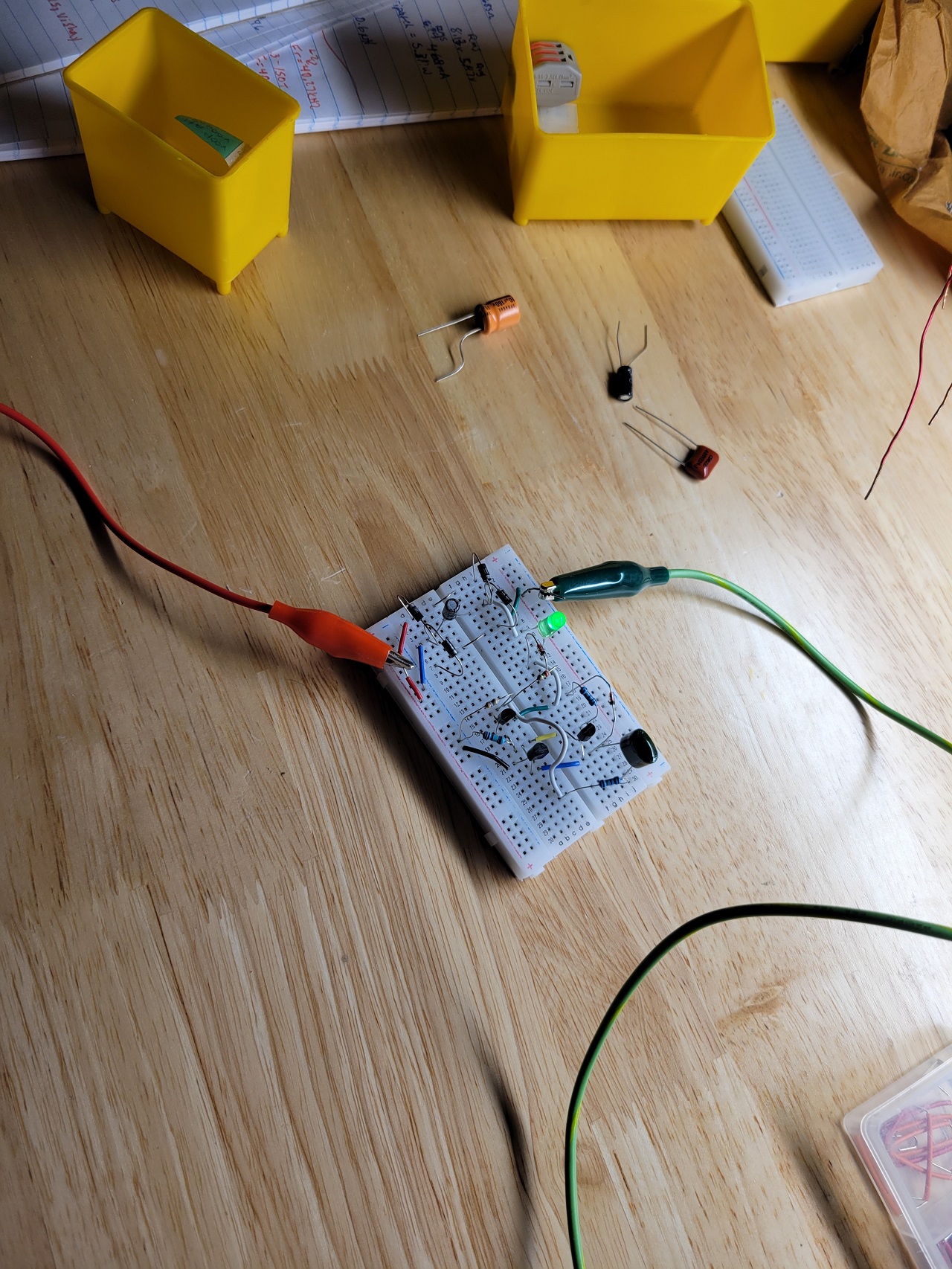
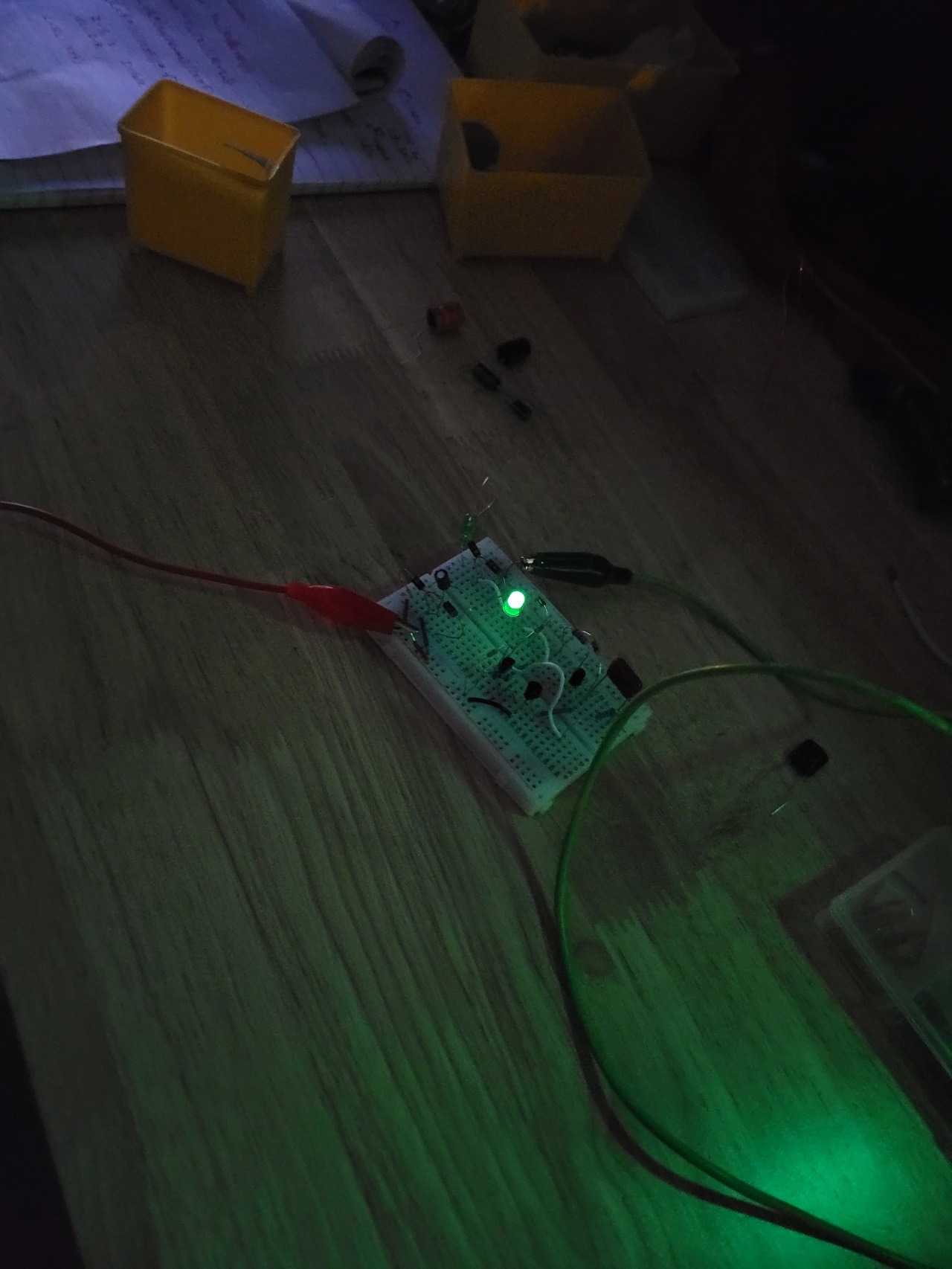
Excellent Replication Alteredunity, bravo

By any chance are you able to describe the operation of maybe this circuit

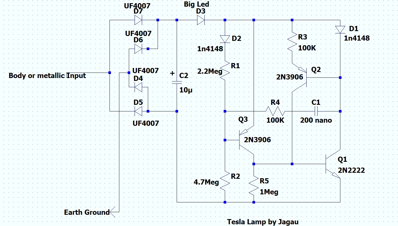
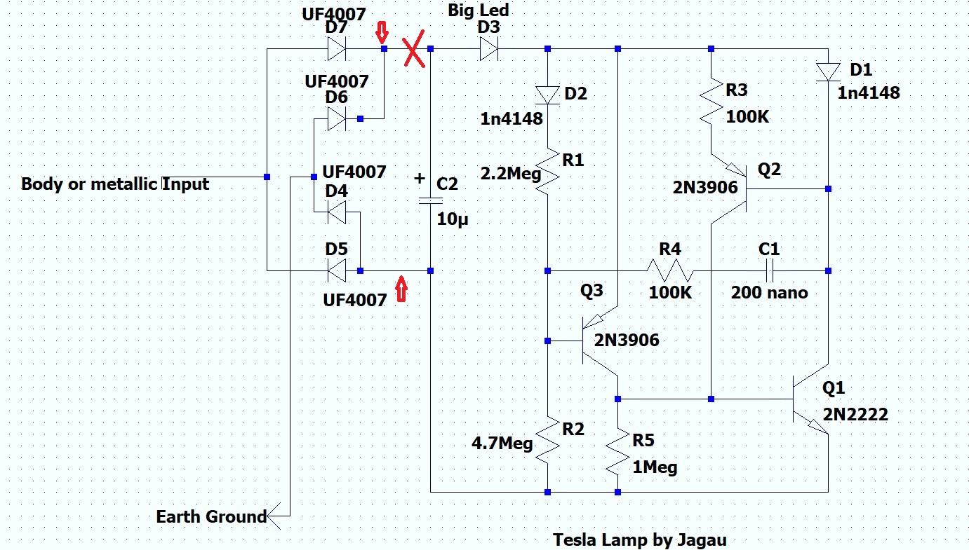
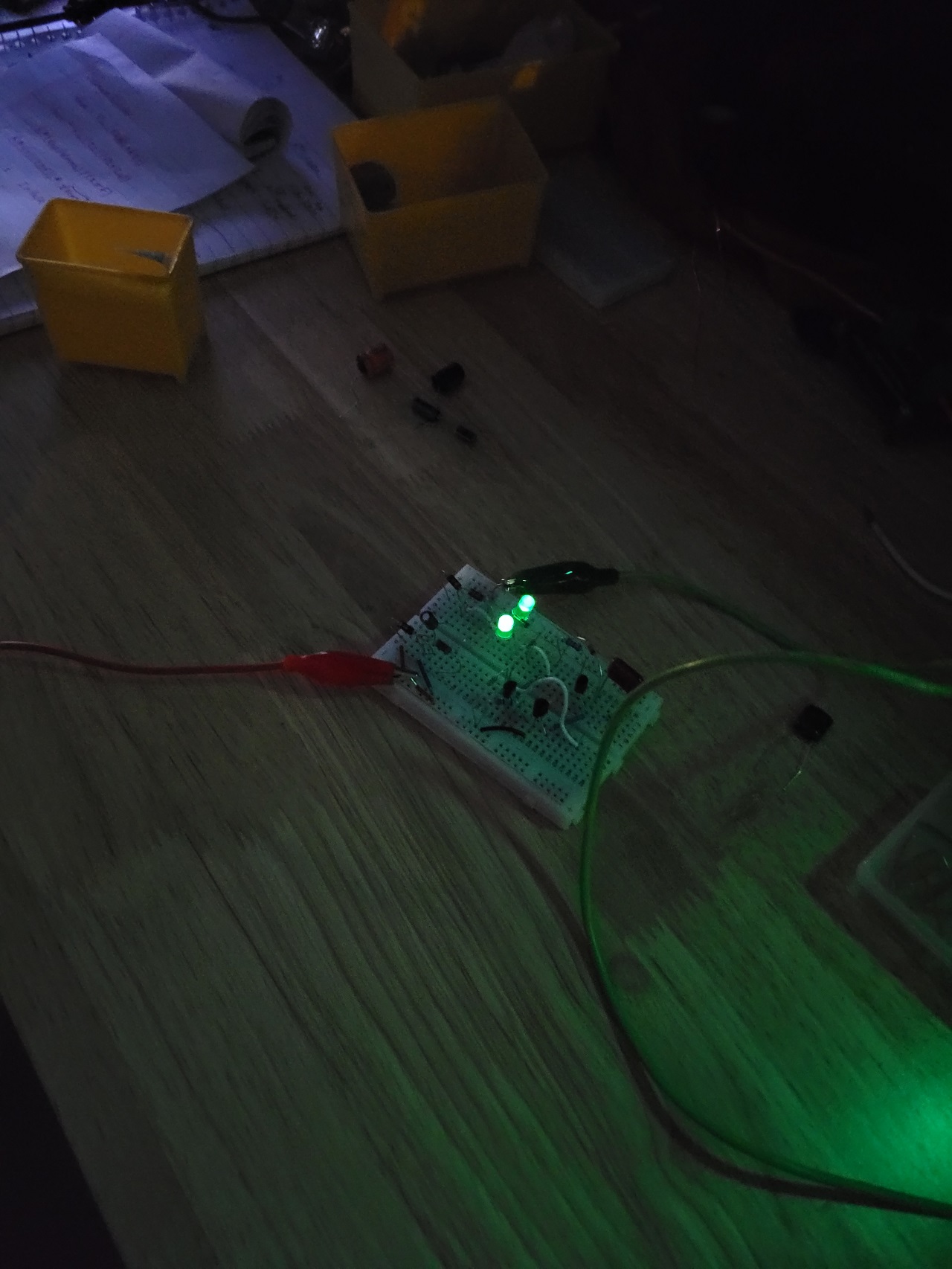
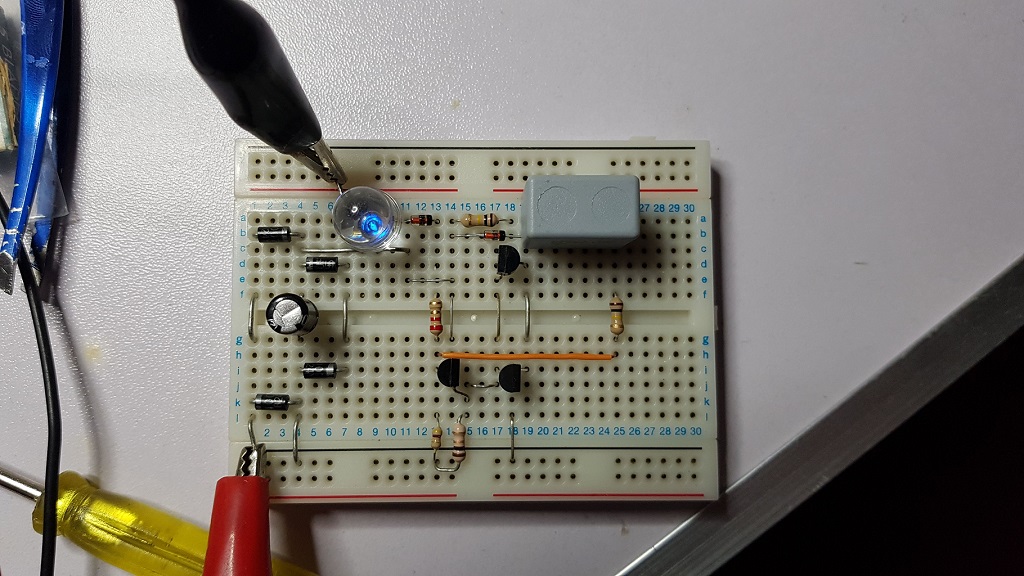
 The purpose of this circuit is to make lit the LED D3 in the small yellow square. The red square represents the supply of the circuit, the ambient AC is rectified in DC tension and stored in C2

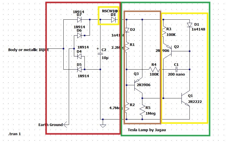
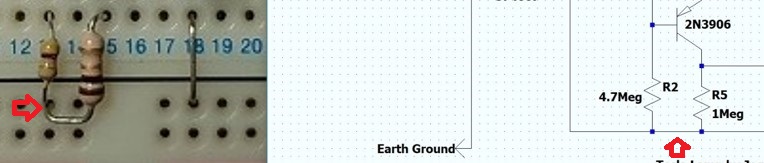
The entire green square represents the switch which is closed only when the voltage divider R1 and R2 reaches the desired tension of activation of the SCR Q1 and Q2. The resistors are very high in order to have a minimum current in the voltage divider.


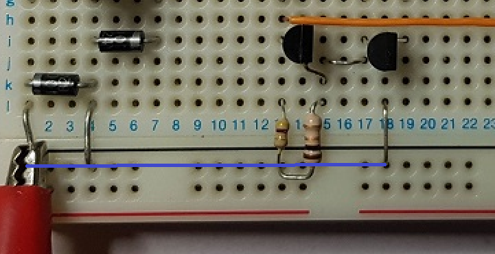
In the following image the two ways to have a SCR operated with two BJT, positive pulse and negative way for momentary pulsed activated by the capacitor C1 and R4 .

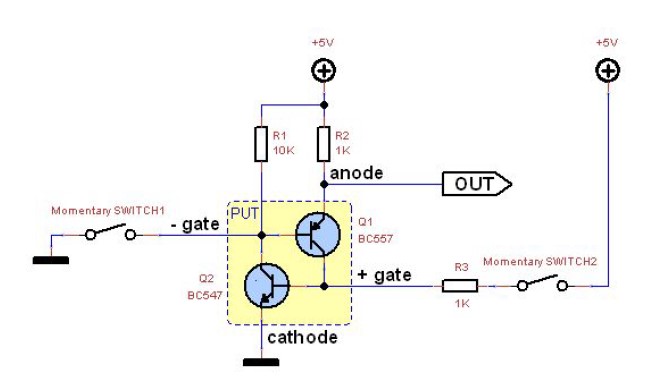
Yes, the Q1et Q2 transistors, in the greater yellow square, are configured as a switch, SCR well known like the SRO, which is triggered by the C1 R4 and Q3 arrangements, in the brown square, configured to activate the PNP which requires pulse to close the SCR Q1 and Q2 and thus lit the white LED.

In a short way, C1 R4 activates Q3 which sends a positive pulse to the base of the SCR Q1-Q2 which puts it in conduction mode and lights the LED and the cycle begins again.

The easiest explanation possible, I hope you understood correctly ?


Jagau

Jagau posted this 08 November 2022

No problem fighter, if you have the time do this little test to check if the voltage from the environment enters your circuit.

At the place where there is an x, cut the circuit there and place a DDM on the + at up and below the -whre you see red arrows. Install your two grounds, and you should already read a DC voltage here on your DDM below 4 volts .   

If you do not have any voltage maybe one of your diodes is badly polarized,

If you have DC voltage, the problem is after the X follows your voltage.


One thing, do not use a schottky diode for the bridge, rather use ultra fast diodes, it's better because we are in very very low voltage and current.
Jagau

Jagau posted this 27 February 2023

Very good job Fighter, you're almost there.
Mine has been flashing for almost two years now and it has never stopped.
I have good news coming, I'm waiting to see your success, congratulations
Jagau

Fighter posted this 06 March 2023

Quoting:Jagau

You are going to have a lot of fun with this very simple little circuit, it makes us smile.

I will surely do. I'm already thinking of what Don Smith once said (quoting from memory): "the grounding can be made in ground or in air". I'll look in the videos when he said that, maybe there is more information about grounding in air. If that can be accomplished then this little device will not need a wire to the ground anymore.

This is another video made in daylight, it shows how strong the luminosity is:

Thank you for sharing this device !

Regards,

Fighter

"If you want to find the secrets of the universe, think in terms of energy, frequency and vibration."
Nikola Tesla
AlteredUnity posted this 09 March 2023

Was able to throw this together pretty fast, and worked somewhat, blinks about every 2 seconds not quite as bright, though didnt have all the right parts. Have too order that polyester capacitor and a few other peices to do it right, then ill cut my leads down to make it a little prettier. Right now in place of the 10uF i have a 4.7uF and as i go lower the frequency of flashes gets higher but lumosity decreases which is a bit self explanitory.

The Red is connected to my workbench, the grounds is coming from my powersupply.

Thanks fighter for the layout, it made the assembly so much quicker. Jagau, you are a smart man, part of this layout reminds me of your SRO. By any chance are you able to describe the operation of maybe this circuit,  but your SRO circuit?

I also noticed i can put two of the LEDs in parallel, and the lumosity of the first doesn't diminish, the other lights just as well:

Thanks for sharing!

Fighter posted this 08 November 2022

Thanks, I may ask for help, I've built one but probably I did something wrong.

Then we left the old aboveunity site and I canceled the project.

I'll need to rebuild it and double-check the schema.

Right now the LED's light is continuous and very weak:

I will come with updates after I'll find some time to rebuild it.

Regards,

Fighter

"If you want to find the secrets of the universe, think in terms of energy, frequency and vibration."
Nikola Tesla
Fighter posted this 08 November 2022

Thank you very much Jagau, that's what I'm gonna do first.

Fighter

"If you want to find the secrets of the universe, think in terms of energy, frequency and vibration."
Nikola Tesla
Jagau posted this 22 February 2023

Hi Fighter
Maybe this connection is missing here on the junction of the two resistors??

We can't see well but the 4.7M and 1meg junction must be grounded look at this it may be the bug

Jagau

Fighter posted this 22 February 2023

Hi Jagau, 

That junction is connected to the ground, I drawn a line showing how the holes are connected in that section:

Ignore the red color of the connector, I tried both ways switching the black and red connectors, the behavior is the same.

I think the best approach to find the issue is to create a new thread with my replication (in order to not derail this thread), to take very close photo of the replication (so I can have a bigger picture) and to draw all the connections like I did with the connection above.

That would help in comparing the circuit with the schema and eventually identify the issue.

If that doesn't work the most radical approach is to remove everything from the board and start rebuilding it.

Right now I don't have too much time to do these as I have a lot of work to do at job and also to create a declaration for the court in the trial I told you about, most likely I'll have time to do all these in the weekend.

Regards,

Fighter

"If you want to find the secrets of the universe, think in terms of energy, frequency and vibration."
Nikola Tesla
Close