Romanian ZPM (Zero Point Module)

  • Topic Is Locked
  • 3.4K Views
  • Last Post 12 February 2023
  • Topic Is Solved
Fighter posted this 07 February 2023

This is the imported thread (from the old aboveunity site) about my ZPM:

For references I will keep the original posting date for every imported post.

Note: This thread is public, everyone can see it, even the visitors which are not members here.

For the posts made by former aboveunity members which are not members on our site I'll use a member placeholder named UndisclosedMember.

Regards,

Fighter

"If you want to find the secrets of the universe, think in terms of energy, frequency and vibration."
Nikola Tesla
  • Liked by
  • Jagau
  • Inception
Fighter posted this 14 July 2019

Hi guys, sorry I was very busy at work and didn't had too much time to continue the experiments.

Few updates...

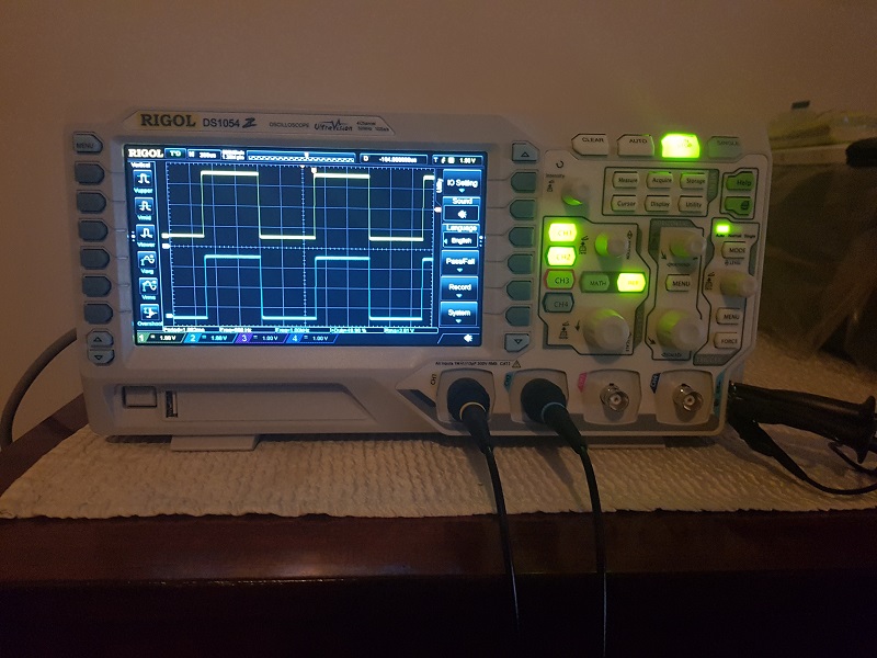
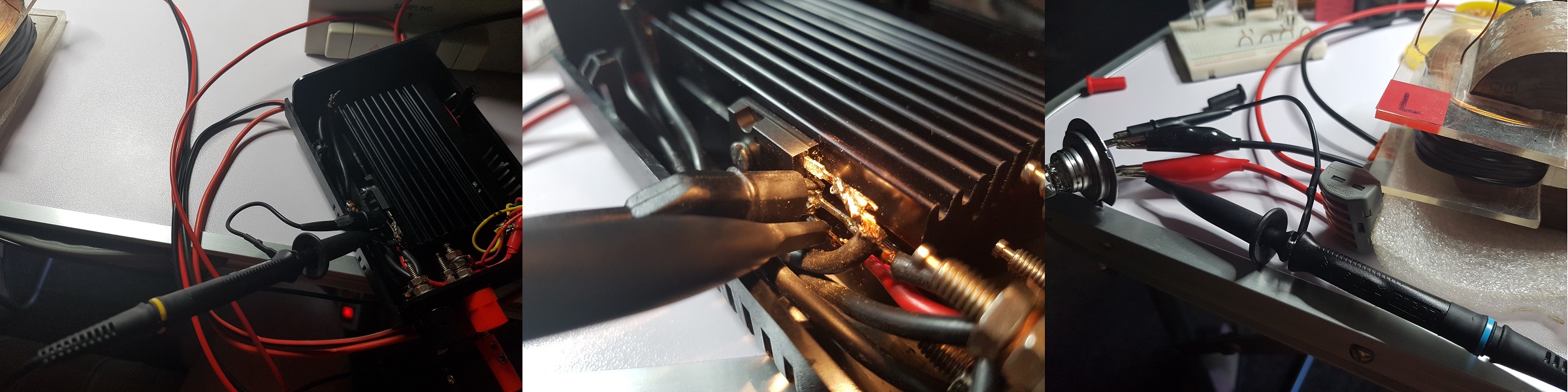
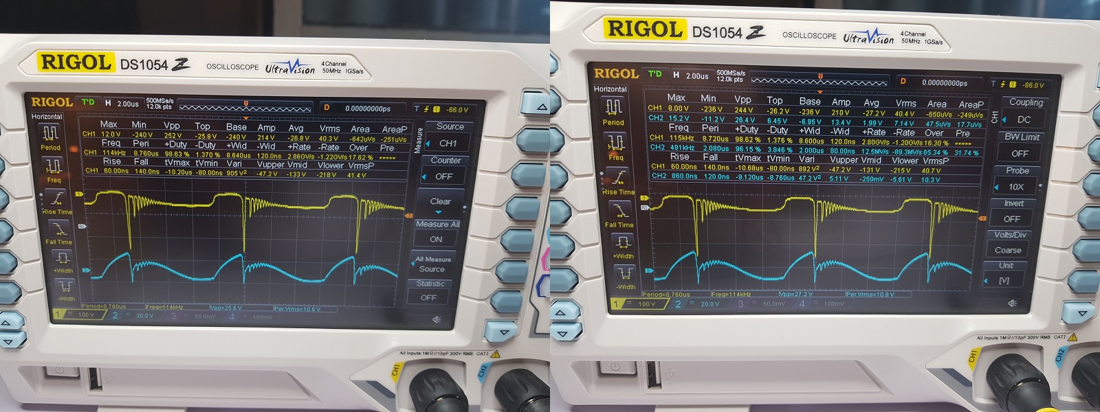
I tried to use my pocket oscilloscope and an 0.5 Ohms current-sensing resistor (I borrowed it from Cd_Sharp) to measure the current on input but for some unknown reason the measurements are not reliable. I guess this is the difference between a pocket oscilloscope and an full-sized oscilloscope so unless I buy a full-sized one I have no equipment to make this kind of measurement.

Probably I will need to buy one but not in the next few weeks.

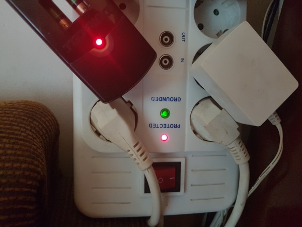
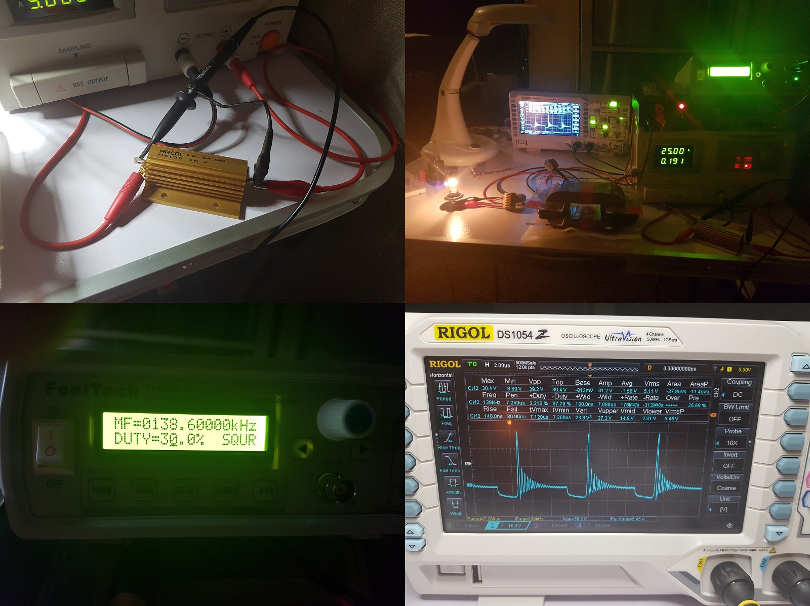
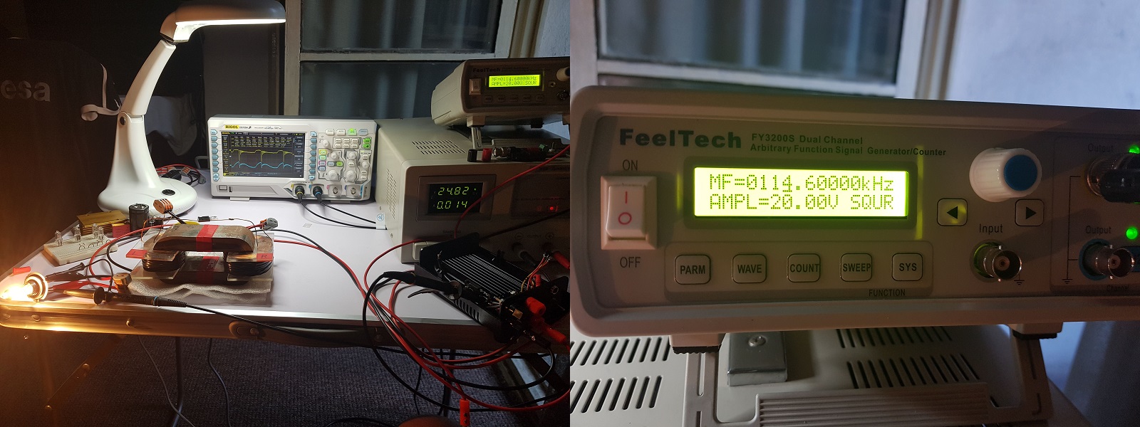
Until then I'm trying an workaround, I bought a socket with energy-meter PeakTech P9035 and I intend to use it on the socket powering my source. My plan is to check the readings on it while the source is in stand-by, then powering up light-bulbs with known wattage then powering up ZPM so I can get at least a approximation of watts used by ZPM depending on what's displayed when powering up light-bulbs connected directly to source's output.

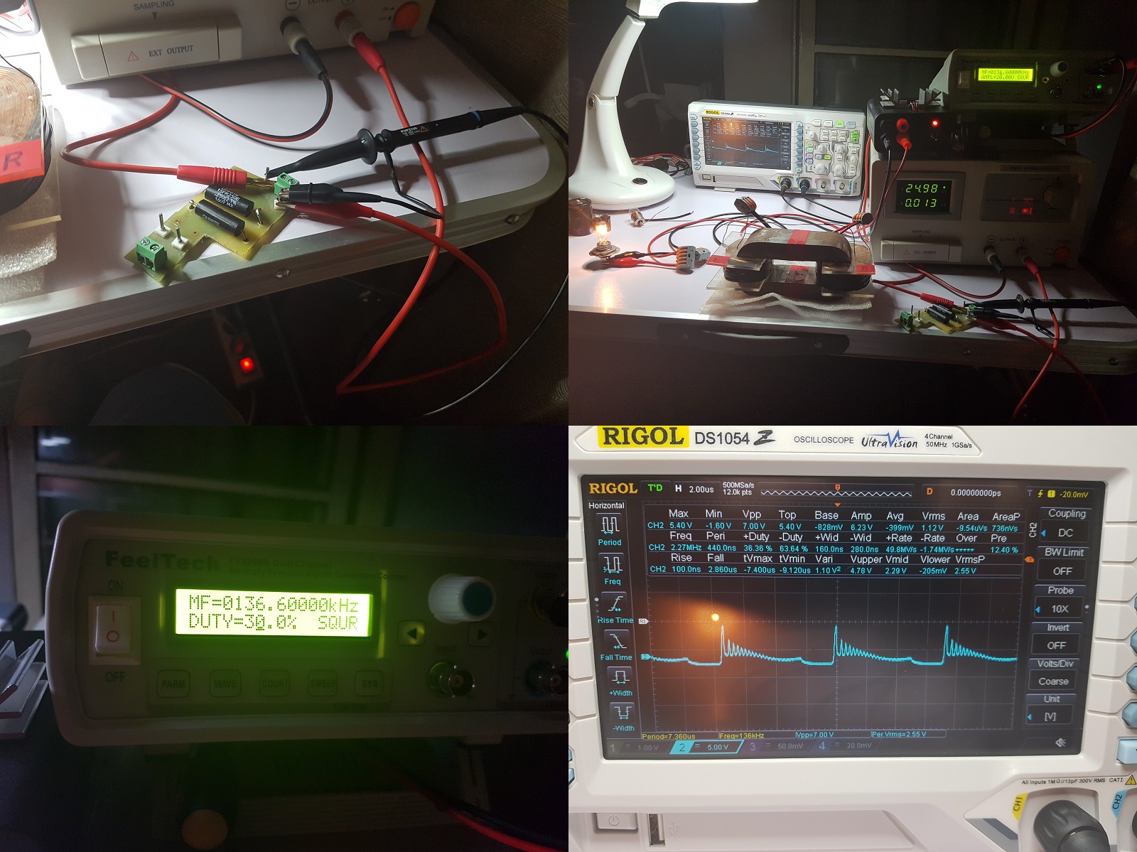
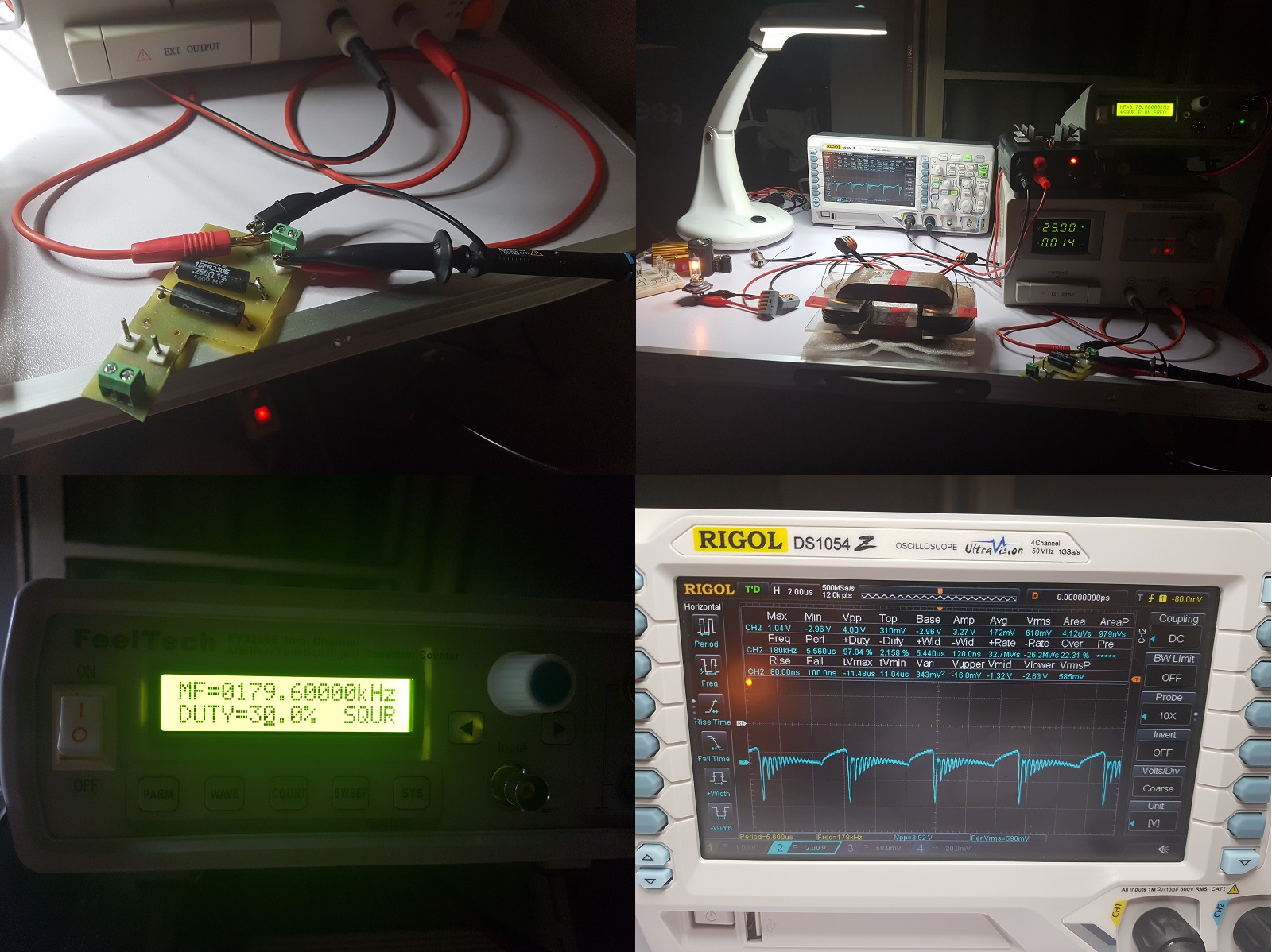
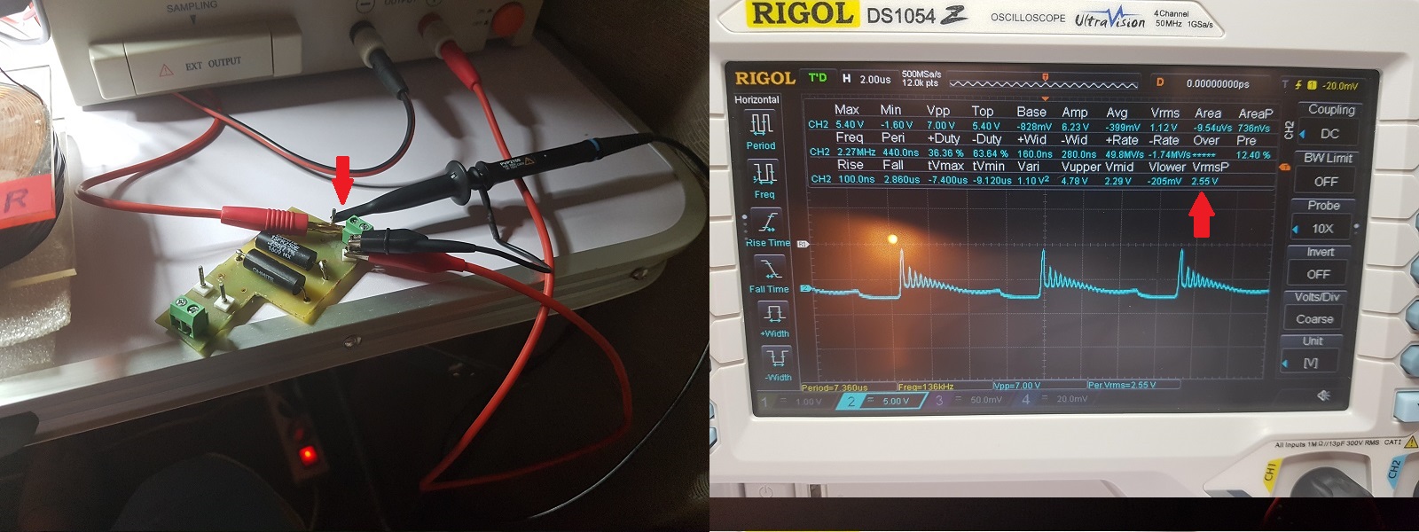
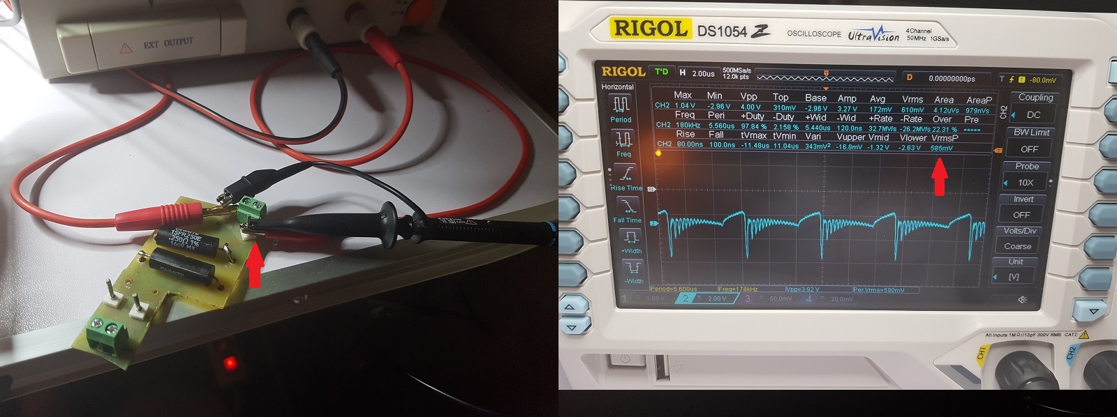
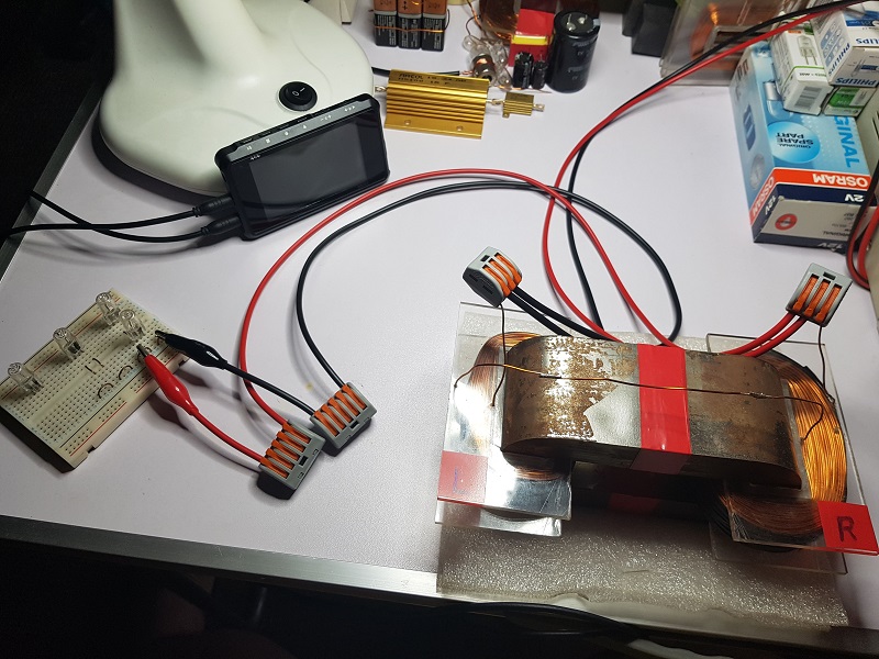
Meanwhile, following JohnStone's advice about possible issues at very high frequencies when using wires with crocodile-type terminals, I bought WAGO connectors and rebuilt all the connections:

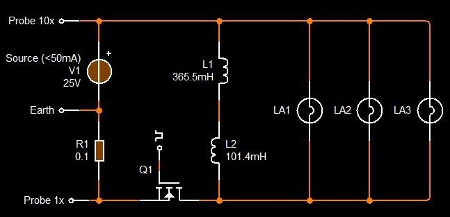
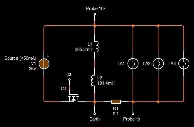
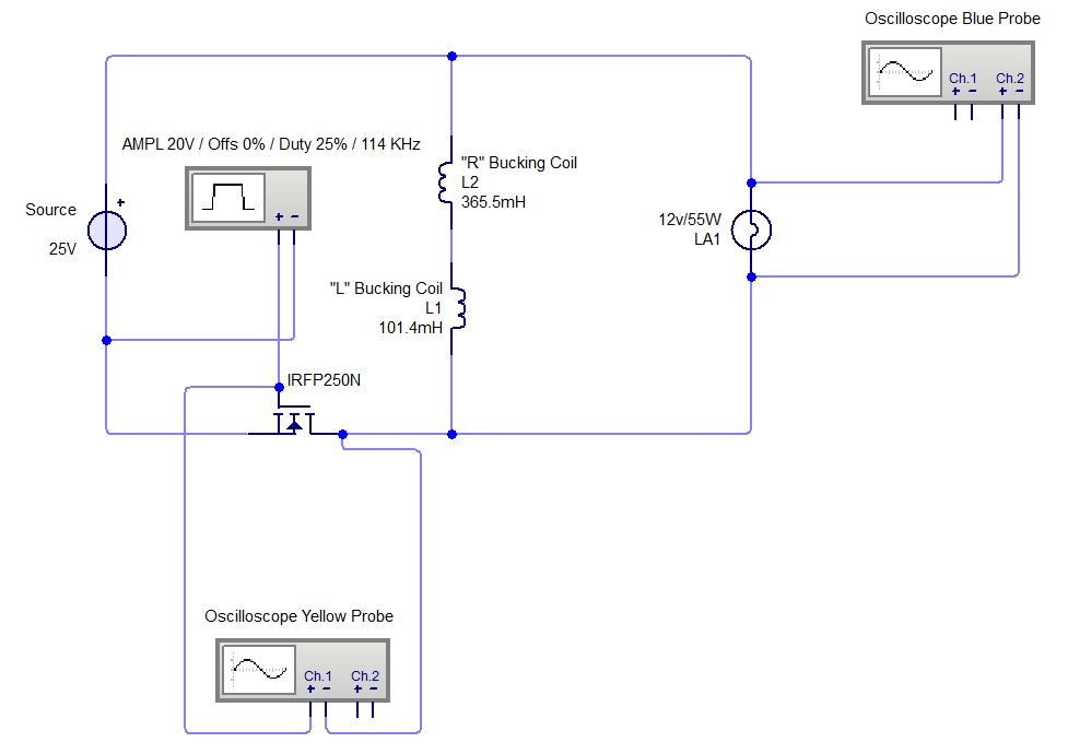
Also I tested the scenario with a diode and an capacitor on source's output in order to filter possible high-frequency pulses sent back to source from the MOSFET driver which could impact source's power readings.

I used a fast Schottky diode (SB560) put on positive output of the source and an 10,000uF/50V electrolytic capacitor put in parallel on source's output.

Didn't noticed major changes on source's readings so I think this scenario is invalid.

Here is the video:


During this test I noticed something (you can see it in the video): adding/removing the capacitor is modifying the optimum frequency of the ZPM even if the capacitor (saw from ZPM's perspective) is behind the MOSFET driver and even behind the Schottky diode. The conclusion would be that this capacitor is somehow a part of the device and it's influencing it, not sure yet how this is possible. Also, my assumption is every DC source have a big capacitor on its output (not sure if it's true for all DC sources) so I guess the other capacitor incorporated in the DC source is being a part and affecting too ZPM's behavior and efficiency.

So when I tested with batteries as input there are two things missing: a ground connection (Chris made references about some devices needing ground connection to work better) and also I didn't had an capacitor in parallel on input as it's happening when using the DC source. Could be a key reason why using the batteries didn't worked well, I'll need to investigate more on this direction.

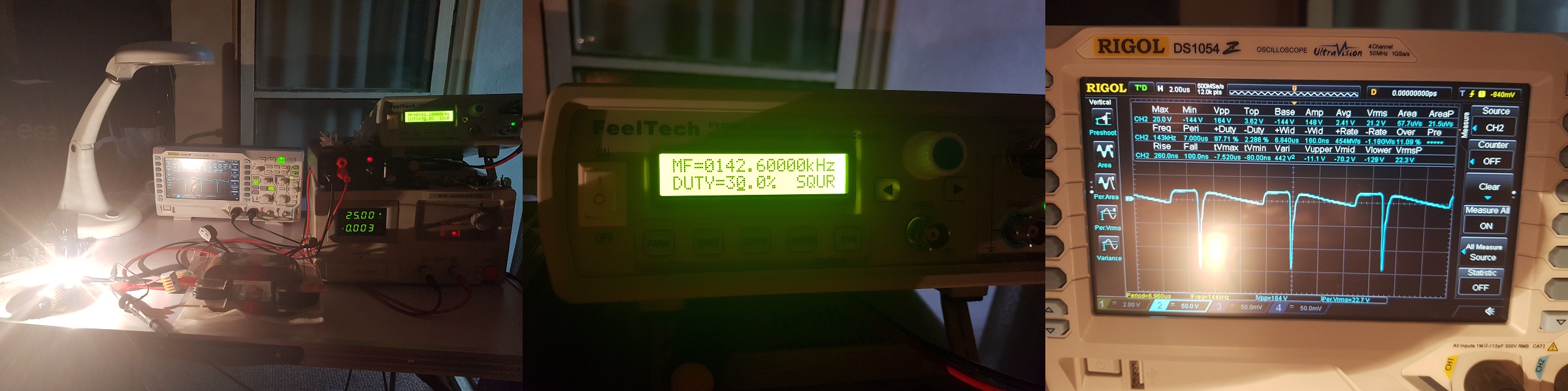
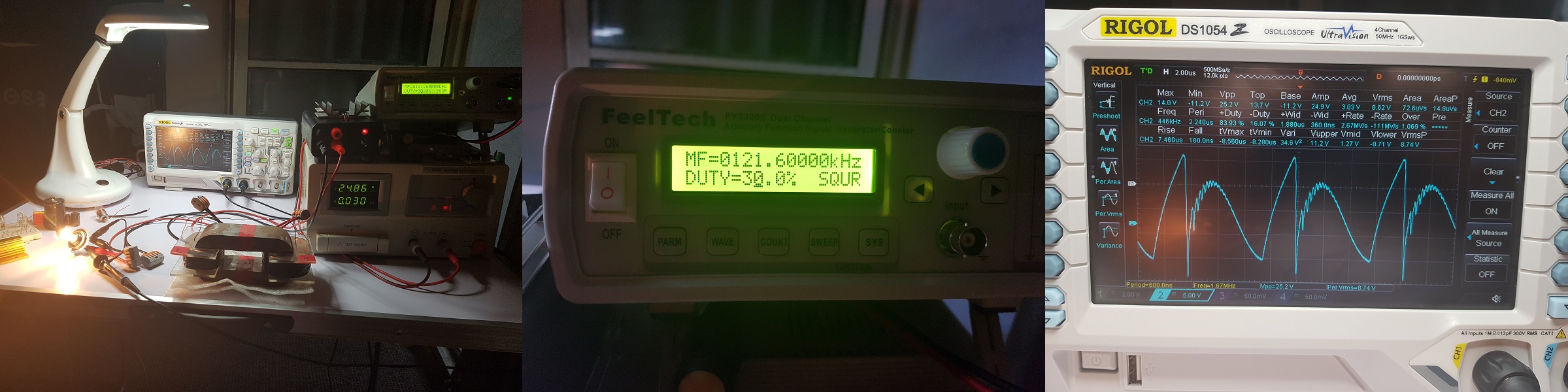
Another things I noticed during a different test is the AWG (diameter) of the input and output wires is very important. I simulated changing the wires AWG by adding/removing connectors in parallel with existing connectors on input and output. I noticed dramatic effects on efficiency and light-bulbs luminosity when changing the wires AWG as you can see the the following video (I'm using 2 x 12V/35W halogen light-bulbs on output). All the wires I use are litz wires. So be aware of this aspect at least when using on output light-bulbs greater than 5W, use a bigger AWG litz wires on input and output.


Something I also noticed when suing 2 x 12V/35W light-bulbs on output, when using those connectors having crocodile-style terminals and small AWG (diameter), the connectors on output are becoming so hot until the plastic which isolates their wires is going to the point of starting to melt even if they don't have direct thermic contact with the halogen lights; in the same time the same type of connectors on input are cold, not  even warmer.

Here could be two possible explanations:

  • let's just suppose there is the same amperage on input and output, the output wires are being hot because of the very high frequency AC while the wires on input are cold because there is DC;
  • or the amperage on the output is much higher than the amperage on the input (as source's readings and the luminosity of the light-bulbs seems to indicate) meaning high COP.

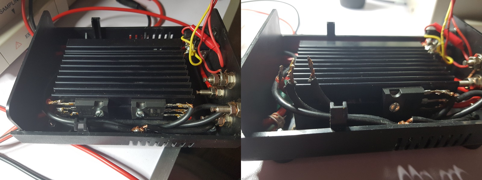
Something else about the MOSFET driver, as you noticed there was a LED indicator on it, inside I had an UA78L12 voltage regulator providing 12V for the LED, it worked for a while as you saw in my initial videos but in time because it had no radiator it stopped functioning as you saw in my other videos. So I decided to replace it with an UA7812 placed on a radiator on the top of the black box. So I removed the UA78L12 and the connectors to the LED and before making changes for UA7812 I ran a test to see if there are any changes in ZPM's behavior and source's reading, there was no difference so the presence of a voltage regulator in the MOSFET driver has no impact on the tests. Just wanted to make sure about it with this occasion.

During the MOSFET driver changes I thought it's good to take some photos of the inside of the black box so you can see what's inside - just a two-channel MOSFET driver and a 12V voltage regulator for powering the LED indicator. Later as the amperage on the ZPM's output will go higher it will be necessary to use those 12V also for a small fan to cool down the MOSFETS' radiator.

So here are the photos with the MOSFET driver opened up during the voltage regulator replacement, I will not post them here as they would take too much space in the thread, you could see them here instead:

https://imgur.com/a/2hRyUzw

I'll continue to post updates here depending on when I'll have again some time for experiments as I'm still very busy at work with the current project.

"If you want to find the secrets of the universe, think in terms of energy, frequency and vibration."
Nikola Tesla
UndisclosedMember posted this 21 July 2019

Fighter :  wow there is alot too digest there, - i have only just started reading this thread, - from the bottom up, but thx for those videos !!

do you have any theores about the wire gauge issue ?, perhaps changing the end with the capacitor...  mabee its just minute changes in resistance....

also am i too understand the experiment with the diode and capacitor, is too take the reverse emf spike off the primary and put it too a cap ?

[ finished reading the thread now ]  did you ever try iron an transformer with your ZPE setup ?  ... i can also confirm anomolous outputs with what seems too be the mr preva experiment,.......    altough im a total SG1 nut .  and atlantis, and frack even  the new one with jews and japs.

  • Liked by
  • Inception
Fighter posted this 22 July 2019

@Patrick: Right now the issue is I'm not sure about the input, I have 3 different readings using 3 different ways to measure the current on input, you can check the video in my next post.

No idea about the cause of the wire gauge issue but I see from experiments there is better efficiency where using bigger wire gauge.

The diode and capacitor are a filter on DC source's output to verify a scenario suggested here in one of the previous posts that the MOSFET driver is sending back to DC source high-frequency pulses that could mess with source's readings (so the source would show incorrect voltage and current on its LED display); so far this scenario seems to be invalid, the DC source is showing the same data with or without that filter.

Actually this is Metglas - a iron core. Its composition is 85-95% iron, 1-5% boron and 5-10% silicon as specified here. But what's special about this core is it's made of foils created by melting the compositions under high heat then cooling it down so fast (almost instantly) that the Metglas alloy don't have time to form a crystalline atomic structure when it become solid again like any metal does when being melt then being cool down normally. That's why the metals obtained this way are also called amorphous (their atomic structure is not crystalline like the usual metals).

"If you want to find the secrets of the universe, think in terms of energy, frequency and vibration."
Nikola Tesla
  • Liked by
  • Inception
Fighter posted this 22 July 2019

Hi guys,

I had some time this weekend so I've made some experiments to check the DC source's readings using normal loads then using the ZPM as load.

Here is the video:


As you can see the source's readings are correct when using a normal load (12V/55W light-bulb) and it's confirmed first by the ampere-meter put in series with the load and second by the voltmeter put in parallel on a 1MOhm/100W aluminum resistor used as a current-sensing shunt.

But when powering up ZPM using the same configuration the DC source, the ampere-meter and the voltmeter are showing very different readings and I have no explanation why and which reading is correct.

Putting that Schottky diode plus a big electrolytic capacitor on source's output as filter against the possible pulses coming back from the MOSFET driver doesn't change the situation, the readings on source's display, ampere-meter and volt-meter still don't match and there are big differences in the current readings on all 3 of them.

So I must admit I don't understand what exactly in this device is making all the measurements on its input being so inaccurate, I always thought the main problem will be to measure the high-frequency AC output of the device not the DC input.

Seems I trusted too much the DC source's readings, I was 100% sure they are accurate as I checked it periodically with other loads and multimeters and the readings were always accurate.

I'll continue the experiments to find out what's going on when I have some free time again.

"If you want to find the secrets of the universe, think in terms of energy, frequency and vibration."
Nikola Tesla
  • Liked by
  • Inception
UndisclosedMember posted this 22 July 2019

Hey Fighter,

Very good thorough measurements!

At High Frequency DMM's are very unreliable. Your video is an excellent example of this problem.

Don't worry you have done nothing wrong! This is good! it goes to our advantage, because together we can very easily resolve this problem. šŸ˜‰

An Oscilloscope can make for much better much more accurate measurements! If we take the Mean or Average measurements then the DMM's will be out of the equation.


Measure Mean Input:

Measure Mean Output:

NOTE: If your PSU is Grounded to the same Ground as your Scope, you may have an issue here.

Ohms Law, I = V / R gives us a 10x factor ( 0.1 Ohms ) that's why the Current Probe is 10x then its just:

Vmean x Imean = Pmean

So please do not worry, this is a well known problem with Digital Multi Meters. šŸ˜‰

  • Liked by
  • Inception
Fighter posted this 28 July 2019

Hi guys, as usually I have some free time in weekend so I'm posting updates.

First, I just received my Rigol DS1054Z oscilloscope.

I needed to review my power installation to make sure (as it's recommended) that the oscilloscope  is grounded and the DC source is not grounded. Basically I've made some changes to make sure the ground from oscilloscope's probes have connection to the grounding pins of the power sockets and also the DC source's negative output have no connection to the grounding pins of the power sockets.

Also I calibrated two of the four probes of the oscilloscope.

Then I connected oscilloscope's blue channel to the output of the ZPM and tested with one 12V/5W ligh-bulb, notice that Vpp=164V, that's the cause why that big capacitor from my Schottky bridge-rectifier was destroyed:

and here I used a 12V/55W light-bulb:

And here it's something which Cd_Sharp noticed, when using the 12W/55W light-bulb the waveform is looking very similar to Graham Gunderson's device waveform:

Here is a video recorded during these two tests:


Then I used one 0.25 ohms current-sensing resistor (half of a shunt I borrowed from Cd_Sharp) to check the DC input.

In the first test I connected the ground of oscilloscope's probe to the resistor connection going the the DC source's positive and the probe itself to the resistor connection going to the ZPM (more specific to the MOSFET driver) and this is the result:

In the second test I rotated oscilloscope's probe: I connected the ground of oscilloscope's probe to the resistor connection going the the going to the ZPM (more specific to the MOSFET driver) and the probe itself to the resistor connection going the the DC source's positive and this is the result:

In these two tests I noticed something strange, the shunt can also show current's direction, so when rotating the ground and the probe of the oscilloscope we should see Vrms positive in one case then we should see Vrms negative in the other case.

Take a look here, observe how oscilloscope's probe is connected in each photo and the Vrms value in each photo. Vrms is never negative so, correct me if I'm wrong, but seems the current is going in both directions in that resistor, one direction is from DC source to the ZPM (which is normal) but also in the other direction from ZPM to the DC source:

Seems to me that while the DC source is powering ZPM in the same time ZPM is also sending power back to the DC source (don't know how it's possible to send power back to the DC source through the MOSFET driver).

This could be another explanation for DC source's "confusion" and also could be a explanation for the following experiment I've made where ZPM seems to show negative consumption if I may say so:


And the last test I've made was also to use the Aluminum 1Ohm/100W resistor as a shunt to check the input:

What's next and I hope I will have some time today (it's 4:36 a.m.) to do is to calibrate the other two oscilloscope probes and to get a synchronized image on the oscilloscope on all four channels with what's happening on:

  • DC source's output;
  • the small coil ("L);
  • the bigger coil ("R");
  • the output (where the light-bulbs are connected).

"If you want to find the secrets of the universe, think in terms of energy, frequency and vibration."
Nikola Tesla
  • Liked by
  • Inception
UndisclosedMember posted this 28 July 2019

Hey Fighter,

Very nice! Nice scope those Rigol's!

Good thorough installation. Yes either way, the Grounds need to be isolated and your method is a much better way to do it!

Where are you looking at the waveform? on the output I am guessing?

EDIT: I zooming in, I see its the output Voltage. Can you please post an image of the gate voltage on the Mosfet and a circuit of where you're measuring please?

I believe what you've build is significant, don't listen to others which may poopoo it! Lets get it measures properly.

  • Liked by
  • Inception
Fighter posted this 28 July 2019

Hi UndisclosedMember,

Thanks, yes it's a nice scope, I like it and I must admit I was inspired to buy it after watching Cd_Sharp's videos, it's the same model šŸ™‚

The only problem is I consumed the investments in my project for the next 2-3 months so for a while I'll need to stay chill and don't buy equipment or electronic components for it. But I think it's okay, for now I have all what I need for the project.

I'm trying to accommodate as fast as possible with how to operate it, it's very different than my DSO203 pocket oscilloscope, I must be very carefully to not blow it, fortunately there are many tutorials on Youtube for this specific model so I hope my learning curve will be fast... šŸ™‚

From what I understood while making research on this the oscilloscope itself should still be grounded but everything else from the circuit being measured (in my case the DC source) should be floating (not grounded). I hope I understood correctly and my current setup is correct.

That waveform is taken with the probe connected to the ZPM's output (more specific to the light-bulb's pins).

Sure, I'll prepare the measurement you're suggesting today probably afternoon, right now it's 4:47 a.m. here and I'm too tired, I don't want to make a mistake and blow the scope or something else... šŸ™‚

"If you want to find the secrets of the universe, think in terms of energy, frequency and vibration."
Nikola Tesla
  • Liked by
  • Inception
UndisclosedMember posted this 28 July 2019

Hi Fighter,

regards from Bucharest, congrats for experimenting and sharing. If I may suggest, to measure the light output for a filament bulb, even with a luxmeter (and almost all kinds of light bulb) it`s not a appropriate way to measure the power consumption. There is a ton of info on the internet, that states that high freq and high voltage gives more light output than straight DC. (the HPS bulbs have better efficiency with digital sources, driven and 20khz, instead on 50hz or 60hz, and also Gavita DE is powered at 400V instead of 230, and this also raisses the efficiency of the system with about 30-50% than 230V at line frequency.) There is also info about AU researchers in the field that were fooled this way.

Also to measure with DMM at such a high freq is not optimal as stated by Chris also (and if I`m not mistaken they are made for sinusoidal signal only), and you can`t see the phase angle this way. I believe that even probing with oscilloscopes, at a low power system, can influence the readings (also a lot of AU researchers fooled this way, even by the WIFI or background radiation). That wattmeter you have from optimusdigital is crap, I have few of them also and when I connect at the load a SMPS power supply, the device for sure doesn`t have any EMI protection and the displayed data is disappearing from time to time, trust me that`s a no no.

The best way I know, to measure power, is always to convert it to filtered DC (place large litic caps after the FWBR)  and measure amps and voltage this way. Also, to be sure that the mosfet driver sourcing current to the system, is not a problem, just pump more juice in the system (at more than 50W input power, you can be sure that the mosfet driver curent is negligible for the total system power consumption).

Also, to measure power output from the power supply, connect two large litic capacitor in parallel with the output and between them place a resistor (measure the voltage drop and you now know for sure the power consumption). 

Also in this way measure the output to the load and you`ll have a much closer picture of what is going on.

Have a nice weekend!

  • Liked by
  • Inception
Fighter posted this 28 July 2019

Hi UndisclosedMember,

I've finished the measurement for MOSFET's gate, sorry but I had some troubles: after I opened the MOSFET driver's box while trying to attach oscilloscope's probe I think I've made a short which burned the MOSFET of the second channel of the driver and damaged it because the DC source entered in protection mode and stayed this way until I removed that MOSFET from the driver:

I needed to make assessment of the situation and found out that the oscilloscope's channel and probe are okay, the signal generator is okay, the only damage was that MOSFET which is okay because I only use one channel of the MOSFET driver for now. Of course de-soldering that MOSFET, removing it from radiator and isolating the wires which made connections to it took a lot of time.

After that I checked that everything is working like before.

EDIT: @UndisclosedMember, please disregard the following measurements, as Vidura pointed out (in his latest post here) they are wrong, I did the measurements again and posted them again, please check my latest post.

Then I took the ground clip of the yellow channel and connected it to the drain of the MOSFET and I connected the probe itself to the gate of the MOSFET. Then I connected the blue channel's probe to the ZPM's output, more specific to the pins of the light-bulb as before:

This is the schema of how I connected oscilloscope's probes:

Photos taken during measurements, just to mention - duty-cycle is 25% like before:

And here are two photos of the oscilloscope's display.

In the first photo I'm showing the measurements for the probe connected to MOSFET (yellow waveform and measurements) and in the second photo I'm showing measurements for both probes (blue waveform and blue measurements are for the probe connected to the outpot on light-bulb's pins):

Something what I noticed is that Vpp = 240V on MOSFET's drain, how is this even possible as IRFPN250N's maximum voltage is 200V ?..

"If you want to find the secrets of the universe, think in terms of energy, frequency and vibration."
Nikola Tesla
  • Liked by
  • Inception
Close